Detailed Design Guide and Configuration Examples of SR-TE Explicit-Path Policy with EVPN VPWS, IOS XR Release - 7.5.x
Available Languages
Download Options
Bias-Free Language
The documentation set for this product strives to use bias-free language. For the purposes of this documentation set, bias-free is defined as language that does not imply discrimination based on age, disability, gender, racial identity, ethnic identity, sexual orientation, socioeconomic status, and intersectionality. Exceptions may be present in the documentation due to language that is hardcoded in the user interfaces of the product software, language used based on RFP documentation, or language that is used by a referenced third-party product. Learn more about how Cisco is using Inclusive Language.
Contents
Introduction
This document describes the detailed design guide with technical descriptions based on the requirements of XYZ Networks and also provides a low-level configuration template and configuration for the use-cases of Segment Routing Traffic Engineering (SR-TE) Explicit-Path Policy with Ethernet VPN (EVPN) Virtual Private Wired Service (VPWS).
1. Background Information
1.1. Out of Scope
This document does not cover the requirements of centralized 'on-demand' SR-TE policies that use XTC controller, EVPN ELAN, and so on, but focuses only on the headend node-driven SR-TE policies with EVPN VPWS overlay.
1.2. Assumption
The reader of this document must be familiar with the concepts of IP/MPLS and Ethernet along with Segment Routing and Traffic Engineering technologies.
1.3. Technical Scope
The main technical scope of this document is limited to:
- OSPF with TI-LFA FRR
- Headend (distributed) controlled SR-TE policies
- Explicit Primary Path and Dynamic IGP-based Failover Paths
- Single-Homed EVPN VPWS
Configuration templates given in this document are referred to as Cisco IOS®-XR 7.5.x.
1.4. Document Summary
Table 1. Document Sections
|
Topic Type |
Topic Name |
Section Number |
|
Introduction |
Background Information |
1 |
|
Requirement |
User Requirements |
2 |
|
Technology Overview |
Segment Routing |
3 |
|
SR-TE Overview |
4 |
|
|
TI-LFA FRR |
5 |
|
|
EVPN Overlay |
6 |
|
|
BoB & Load Balancing |
7 |
|
|
Configuration Templates |
The Complete Design Solution |
8 |
|
Sample Configuration & Show Commands |
9 |
Requirement
2. User Requirements
2.1. Requirement Summary
The service provider XYZ Networks has a requirement to build a green field network via Cisco NCS 5500 devices.
The purpose is to carry a multicast data stream (voice, video) as a service across a layer2 transport network with certain requirements, one of those is to traffic engineer the traffic paths through the network.
They have preferred SR for transport labels, SR-TE for traffic engineering, and EVPN as an overlay to provide service labels.
2.2. Components Used
The user XYZ has converged on the NCS 5500 routers and line cards:
Table 2. Project Hardware Requirements
|
PE Nodes |
PIDs |
|
Chassis |
NCS-5504 |
|
MPA/LCs connecting P Nodes |
NC55-36X100G-A-SE |
|
MPA/LCs connecting CE Nodes |
NC55-36X100G-A-SE |
|
P Nodes |
PIDs |
|
Chassis |
NCS-5508 |
|
MPA/LCs connecting other P Nodes |
NC55-36X100G-A-SE |
|
MPA/LCs connecting PE Nodes |
NC55-36X100G-A-SE |
This section gives an overview of the technologies to be used with brief descriptions.
Technology Overview
3. Segment Routing
3.1. What is Segment Routing?
Segment Routing is the latest advanced MPLS technology that is in the process to replace the traditional LDP and RSVP-TE protocols with the introduction of label distribution and traffic engineering under one umbrella and to make it happen only via link-state IGP/BGP protocols.
Segment routing is a method to forward packets on the network based on the source routing paradigm. The source chooses a path and encodes it in the packet header as an ordered list of segments. Segments are an identifier for any type of instruction. For example, topology segments identify the next hop toward a destination. Each segment is identified by the segment ID (SID) which consists of a flat unsigned 20-bit integer.
3.2. Segment Identifiers
Figure 1. SR Node SIDs and Adjacency SIDs
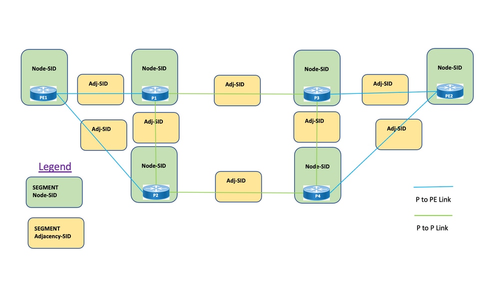
Segments: Interior gateway protocol (IGP) distributes two types of segments: Prefix segments and Adjacency segments. Each router (node) and each link (adjacency) has an associated segment identifier (SID).
Prefix SID: A prefix segment is a global segment, so a prefix SID is globally unique within the segment routing domain as illustrated in Figure 1. A prefix SID is associated with an IP prefix. The prefix SID is manually configured from the segment routing global block (SRGB) range of labels and is distributed by IS-IS or OSPF. The prefix segment steers the traffic along the shortest path to its destination.
- Uses SR Global Block (SRGB)
- SRGB advertised with router capabilities TLV – In the configuration, Prefix-SID can be configured as an absolute value or an index
- In the protocol advertisement, Prefix-SID is always encoded as a globally unique index. The index represents an offset from SRGB base, zero-based numbering, that is, 0 is the 1st index. For example, index 1 à SID is 16,000 + 1 = 16,001
Node SID: A node SID is a special type of prefix SID that identifies a specific node. It is configured under the loopback interface with the loopback address of the node as the prefix. A prefix segment is a global segment, so a prefix SID is globally unique within the segment routing domain.
In other words, the Node segment is a Prefix segment associated with a host prefix that identifies a node.
- Equivalent to a router-id prefix, which is a prefix that identifies a node
- Node-SID is Prefix-SID with N-flag set in the advertisement
- By default, each configured Prefix-SID is a node-SID
- 'regular' (that is, non-Node-SID) Prefix-SID is configurable for IS-IS
Adjacency SID: An adjacency segment is identified by a label called an adjacency SID, which represents a specific adjacency, such as an egress interface, to a neighboring router. The adjacency SID is distributed by IS-IS or OSPF. The adjacency segment steers the traffic to a specific adjacency. An adjacency segment is a local segment, so the adjacency SID is locally unique relative to a specific router.
- Locally significant
- Automatically allocated for each adjacency
- Always encoded as an absolute (that is, not indexed) value
Binding SID or BSID: It is a locally significant SID associated with SR Policy. It helps to steer packets into its associated SR policy. The binding segment is a local segment that identifies an SR-TE policy. Each SR-TE policy is associated with a binding segment ID (BSID).
The BSID is a local label that is automatically allocated for each SR-TE policy when the SR-TE policy is instantiated. BSID can be used to steer traffic into the SR-TE policy and across domain borders, which creates seamless end-to-end inter-domain SR-TE policies.
4. SR-TE Overview
4.1. What is SR-TE?
Segment Routing Traffic Engineering (SR-TE) transforms the simple, stateless source routing mechanism of SR to an advanced level to program and steer the data traffic through pre-defined paths that avoid congestion and provide alternate paths just like an express-way live traffic map.
This is achieved when you administratively configure policies defined via a combination of various constraints which programs the primary as well as backup paths from source to destination nodes. The controller can be centralized (SDN) or distributed (headend) which depends on the network requirement.
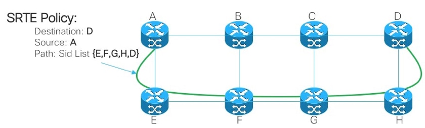
Let’s consider the topology presented in Figure 2. Assume the cost of the links are default values and the shortest path to reach D from A is A-B-C-D but the low latency path is A-E-F-G-H-D. The operator can define the traffic-engineered path as per the requirement (For example, Latency) and express it in the form of a segment ID list – (A, E, F, G, H, D). Unlike RSVP-TE, the state of this policy is maintained at router A only and not the entire routers that the packets traverse (that is, E, F, G, and H).
Figure 2. Example of SR-TE Administratively Defined Path
4.2. SR-TE Policy
Segment routing for traffic engineering (SR-TE) uses a 'policy' to steer traffic through the network. An SR-TE policy path is expressed as a list of segments that specifies the path, called a segment ID (SID) list. Each segment is an end-to-end path from the source to the destination and instructs the routers in the network to follow the specified path instead of following the shortest path calculated by the IGP. If a packet is steered into an SR-TE policy, the SID list is pushed on the packet by the head-end. The rest of the network executes the instructions embedded in the SID list.
An SR-TE policy is identified as an ordered list (head-end, color, end-point):
- Head-end – Where the SR-TE policy is instantiated
- Color – A numerical value that distinguishes between two or more policies to the same node pairs (Head-end – Endpoint)
- End-point – The destination of the SR-TE policy
- Every SR-TE policy has a color value. Every policy between the same node pairs requires a unique color value.
An SR-TE policy is configured with one or more candidate paths which include primary and backup paths.
For instance, the primary path of the policy can be explicitly defined with Adjacency SIDs and in case of failure scenarios, the backup path can be a dynamic one taken care of by the IGP metric.
5. TI-LFA FRR
5.1. Overview
Topology independent loop-free alternate (TI-LFA) is a feature that protects links, nodes, and SRLGs. It is simple to configure; only two lines of configuration are required to implement a simple TI-LFA configuration into the router. It does not require any changes to the protocols that exist used in the router. Figure 3. shows the primary traffic path and pre-calculated backup path by TI-LFA for Local Link Failure and Node Failure Scenarios.
Figure 3. TI LFA Link Failover Scenario
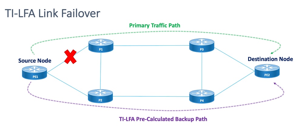
Figure 4. TI LFA Node Failover Scenario
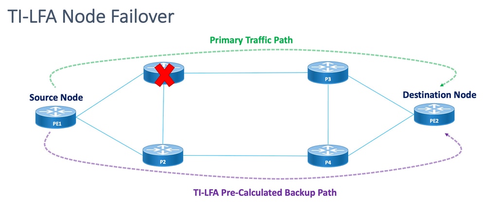
Every protected node and path has a pre-calculated backup path that can be enabled quickly. The convergence time for a protected path is 50 milliseconds or less. This means that even the most latency or packet loss-sensitive applications can work with no disruptions in case a node or a link fails. TI-LFA calculates the backup path and temporarily removes the protected link or node from the database. After this, it calculates the backup path with the shortest path first. This ensures that the backup path has the lowest possible metric cost while it avoids the protected path. A traffic-engineered tunnel that follows the backup path is used for traffic if a failure occurs. A repair label list determines the path for the packets that need a new route to their destination. A repair label list is a normal label stack but it is only used when a failure occurs in the protected route.
5.2. Failure Detection Method Impact on FRR
Fast Reroute for SR-TE traffic-engineered paths is configured as a means to switch traffic in case of failover scenarios from the primary path to backup paths within as close to 50 msec as feasible. The fast reroute feature is configured under IGP (OSPF/ISIS) protocol. The convergence time depends on the method by which the link failure detection happens. In the case of a fiber cut the detection is immediate and the possibility to get a sub 50 msec of convergence is high. However, in case the link failure detection has to be done by BFD with an interval of 15 msec (multiplier x3). The convergence time is mostly more than 50 msec.
5.3. Microloop Avoidance with SR
Microloops are brief packet loops that occur in the network that follows a topology change (link down, link up, or metric change events). Microloops are caused by the non-simultaneous convergence of different nodes in the network. If nodes converge and send traffic to a neighbor node that has not converged yet, traffic can be looped between these two nodes, which results in packet loss, jitter, and out-of-order packets.
The Segment Routing Microloop Avoidance feature detects if microloops are possibly followed by a topology change. If a node computes that a microloop can occur on the new topology, the node creates a loop-free SR-TE policy path to the destination with the use of a list of segments. After the RIB update delay timer expires, the SR-TE policy is replaced with regular forwarding paths. There is a default timer for RIB update delay which is taken care of by TI-LFA.
6. EVPN Overlay
EVPN is a technology initially designed for Ethernet multipoint services, with advanced multi-homing capabilities, with the use of BGP to distribute MAC address reachability information over the MPLS network, while it brings the same operational and scale characteristics of IP VPNs to L2VPNs. Today, beyond DCI and E-LAN applications, the EVPN solution family provides a common foundation for all Ethernet service types, which includes E-LINE, and E-TREE, as well as data center routing and bridging scenarios. EVPN also provides options to combine L2 and L3 services in the same instance.
EVPN is a next-generation solution that provides Ethernet multipoint services over MPLS networks. EVPN operates in contrast to the Virtual Private LAN Service (VPLS) that exists which enables BGP control-plane-based MAC learning in the core. In EVPN, PEs that participate in the EVPN instances learn user MAC routes in Control-Plane with the use of MP-BGP protocol.
EVPN brings a number of benefits as mentioned:
- Per-flow redundancy and load balancing
- Simplified Provisioning and Operation
- Optimal forwarding
- Fast Convergence
- MAC address scalability
- Multivendor solutions under IETF standardization
The MAC addresses learned on one device need to be learned or distributed on the other devices in a VLAN. EVPN Software MAC Learning feature enables the distribution of the MAC addresses learned on one device to the other devices connected to a network. The MAC addresses are learned from the remote devices with the use of BGP.
In these sections, you learn about some of the benefits and route types of EVPN in general and then understand the solution-specific components that are applied to the design of XYZ Network Services.
6.1. EVPN Benefits
L2VPN and L3VPN not only provide services under one solution umbrella with help of various route types, EVPNs solve two long-standing limitations for Ethernet Services in Service Provider Networks:
- Multi-Homed and All-Active Ethernet Access
- Service Provider Network—Integration with Central Office or with Data Center
6.1.1. Multi-Homed and All-Active Ethernet Access
The figure demonstrates the greatest limitation of traditional L2 Multipoint solutions like VPLS.
Figure 5. EVPN All-Active Access
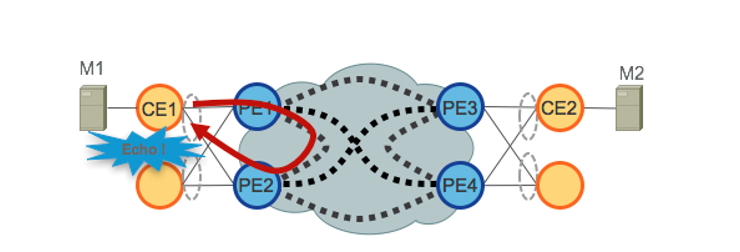
When VPLS runs in the core, loop avoidance requires that PE1/PE2 and PE3/PE4 only provide Single-Active redundancy toward their respective CEs. Traditionally, techniques such as mLACP or Legacy L2 protocols like MST, REP, G.8032, and so on were used to provide Single-Active access redundancy.
The same situation occurs with Hierarchical-VPLS (H-VPLS), where the access node is responsible to provide Single-Active H-VPLS access by active and backup spoke pseudowire (PW).
All-Active access redundancy models are not deployable as VPLS technology lacks the capability to prevent L2 loops that derive from the forwarding mechanisms employed in the Core for certain categories of traffic. Broadcast, Unknown-Unicast, and Multicast (BUM) traffic sourced from the CE is flooded throughout the VPLS Core and is received by all PEs, which in turn flood it to all attached CEs. In our example, PE1 can flood BUM traffic from CE1 to the Core, and PE2 can send it back toward CE1 when received.
EVPN uses BGP-based Control Plane techniques to address this issue and enables Active-Active access redundancy models for either Ethernet or H-EVPN access.
6.2. EVPN Route-Types
EVPN defines a new BGP NLRI that is used to carry all EVPN routes. EVPN NLRI is carried in BGP with the use of multiprotocol extensions with an AFI of 25 (L2VPN) and a SAFI of 70. BGP capabilities advertisement is used to ensure two speakers support EVPN NLRI.
Figure 6. EVPN NLRI
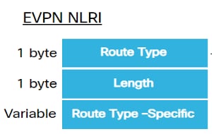
The relevant EVPN route types needed for this implementation are described here:
6.2.1. Route Type 1 - Ethernet Auto-Discovery (AD) Route
The Ethernet Auto-Discovery (AD) routes are advertised per EVI and per ESI basis. These routes are sent per ES. They carry the list of EVIs that belong to the ES. The ESI field is set to zero when a CE is single-homed. This route type is used for a mass withdrawal of MAC addresses, aliasing for load balancing, and Split Horizon Filtering.
6.2.2. Route Type 4 - Ethernet Segment Route
Ethernet segment routes enable the connection of a CE device to two or PE devices. ES route enables the discovery of connected PE devices that are connected to the same Ethernet segment, that is, redundancy group discovery. It is also used for the designated forwarder (DF) election.
6.3. EVPN Host Connectivity
These EVPN modes are supported:
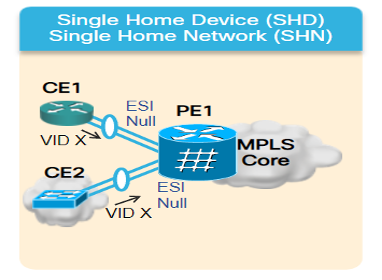
- Single homing - This enables you to connect a user edge (CE) device to one Provider Edge (PE) device. In this ESI value is null for each PE-CE link.
- Multihoming - This enables you to connect a user edge (CE) device to two or more Provider Edge (PE) devices to provide redundant connectivity. No Interchasis link is required. The redundant PE device ensures that there is no traffic disruption when there is a network failure. The types of multihoming are:
Figure 7. EVPN Single Homing
Multihoming - These are the types of multihoming:
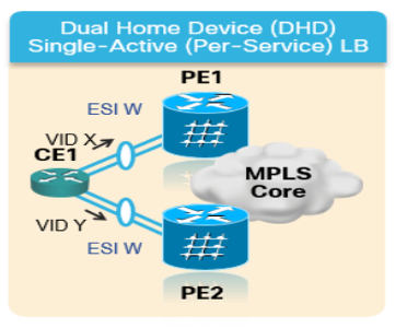
1. Single-Active - In a single-active mode, only a single PE among a group of PEs attached to the particular Ethernet Segment is allowed to forward traffic to and from that Ethernet Segment.
Figure 8. EVPN Single-Active
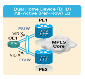
2. Active-Active - In active-active mode, all the PEs attached to the particular Ethernet Segment are allowed to forward traffic to and from that Ethernet Segment.
Figure 9. EVPN Dual Active
7. BoB & Load Balancing
7.1. BFD over Bundle (BoB)
Bidirectional Forwarding Detection (BFD) provides low-overhead, short-duration detection of failures in the path between adjacent forwarding engines. BFD allows a single mechanism to be used for failure detection over any media and at any protocol layer, with a wide range of detection times and overhead. The fast detection of failures provides an immediate reaction to failure in the event of a failed link or neighbor.
This would trigger the IGP to start forwarding the traffic towards the backup path already calculated with the use of FRR (in the case of IGP) and PIC (in the case of BGP).
In the BFD Over Bundle (BoB) feature, the IPv4 BFD session runs over every active bundle member.
Figure 10. BoB Logical Diagram
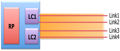
Bundlemgr considers BFD states, in addition to the L1/L2 states that exist, to determine member link usability. The bundle member state is a function of:
L1 state (physical link)
L2 state (LACP)
L3 state (BFD)
BFD Agent still runs on the line card. BFD states of bundle member links are consolidated on RP. Member links must be connected back-to-back, without any L2 switches in between. BoB feature is configured in all Bundle Ethernet interfaces across the XYZ Network.
7.2. Load Balancing
Per Flow ECMP Load Balancing in the concerned network spans across inter Bundle Ethernet interfaces and intra-bundle ethernets (between physical members of a Bundle Interface). This is applicable across the network from PE to PE (Core Load Balance) as well as PE to CE (AC Load-Balance) as discussed.
7.2.1. Core Load Balancing with FAT Label
As per the scope of XYZ Network, you must consider only per-flow ECMP (equal-cost multipath) Load Balancing as mentioned:
Routers typically load balance traffic based on the lower-most label in the label stack which is the same label for all flows on a given pseudowire. This can lead to asymmetric load balancing. The flow, in this context, refers to a sequence of packets that have the same source and destination pair. The packets are transported from a source provider edge (PE) to a destination provider edge PE.
Flow-Aware Transport Pseudowire (FAT PW) provides the capability to identify individual flows within a pseudowire and provide routers the ability to use these flows to load balance traffic. FAT PWs are used to load balance traffic in the core when equal-cost multipaths (ECMP) are used. A flow label is created based on indivisible packet flows that enter a pseudowire and is inserted as the lower-most label in the packet. Routers can use the flow label for load balancing which provides a better traffic distribution across ECMP paths or link-bundled paths in the core.
An extra label is added to the stack, called the flow label, which is generated for each unique incoming flow on the PE. A flow label is a unique identifier that distinguishes a flow within the PW and is derived from source and destination MAC addresses, and source and destination IP addresses. The flow label contains the end of the label stack (EOS) bit set. The flow label is inserted after the VC label and before the control word (if any). The ingress PE calculates and forwards the flow label. The FAT PW configuration enables the flow label. The egress PE discards the flow label such that no decisions are made.
7.2.2. Attachment Circuit Load Balancing
For load balancing of AC Bundle members, however, you need a different approach due to the absence of SR-MPLS in this section of the network.
The per-flow load balancing here can be achieved when specific l2vpn configuration knobs across all PE routers are explicitly tweaked. It can be per SRC/DST MAC or SRC/DST IP as per the requirement.
Configuration Templates and Command Samples
8. The Complete Design Solution
This section discusses the complete design details stitched by all the different individual components which have been explained in earlier sections. This section depicts the topology and the relevant configuration template with reference to Cisco IOS-XR 7.5.x.
8.1. Low-Level Requirements
For the normal traffic scenario, the traffic flow is designed to propagate always between the service terminations of PE1 and PE3 and between PE2 and PE4 only. The primary objective in this situation is to keep the traffic path fully disjointed as shown in Figure 12.
The concerned traffic here would be encapsulated multicast flows through the EVPN overlay. From CE1 and CE2 nodes, the multicast media streams(voice/video) comes in which, it can get encapsulated at the PE1 and PE2 nodes and transported over the EVPN L2 overlay to CE3 and CE4 nodes respectively after it gets decapsulated at PE3 and PE4 nodes respectively.
Hence, the source-destination traffic pair is considered to be PE1-PE3 and PE2-PE4 henceforth under all circumstances unless otherwise mentioned. For requirement details, please refer to sub-section 2.2.
8.2. Design Summary
To achieve the requirements, OSPF is chosen as underlay IGP as desired by XYZ Networks. To steer the encapsulated multicast stream across the source-destination traffic pair through the desired path, SR-TE has to be implemented between PE nodes.
The SR-TE policies have been designed with Explicit-Path and Dynamic IGP Paths.
The Explicit Paths cover the:
- Normal Traffic Scenario
- Failover Scenario till alternate path options are available
The Dynamic IGP Paths cover:
- Backup Path for Failover Scenario where alternate path options are NOT available
The features like BFD, TI-LFA, and Microloop Avoidance are configured under OSPF as shown in the configuration templates sub-sections.
For normal traffic scenarios, the configuration template and other details are mentioned in sub-section 8.5.1.
For traffic failover scenarios, the configuration template and other details are mentioned in sub-section 8.5.2.
Apart from these, the requirements such as microloop avoidance and sub 50 msec of convergence in case of failure scenarios are taken care of as well.
8.3. Design Blocks
This sub-section captures all the design blocks which are subsequently addressed thoroughly in these sections.
General Design Overview (Layer1):
- The MTU size across the XYZ Network is fixed at '9216' with an aim to support up to 5 to 6 SR label-stack
- 'BFD over Bundle' is implemented with an interval of 15 msec to detect fiber cut sub 50 msec
OSPF/SR-TE Design Overview:
- OSPF as IGP protocol with TI-LFA configured to provide FRR under 50 msec of convergence time
- Transport Layer based on Segment Routing as Forwarding Plane and OSPF as the routing protocol
- In XYZ Network, Segment Routing Traffic Engineering explicit path steers the traffic in all required primary path directions. In case of link/node failover scenarios, the traffic is routed by a dynamic igp path
- Microloop Avoidance and OSPF Max-Metric are also a part of this design
BGP/RR Design Overview:
- There are two RRs configured in a cluster to provide redundancy
- The XYZ Network, BGP process in each PE forms 'IPv4' and 'L2VPN EVPN' peering with both RRs separately
Service Design Overview:
- Service Layers are built on top of BGP based Control Plane and Layer 2 point-to-point EVPN (EVPN-VPWS)
- The multicast video (UDP) traffic is sent encapsulated across the point-to-point EVPN-VPWS PWs
- ECMP Load Balancing is achieved by configuration of FAT label under EVPN section
- The service aims to support up to 5 to 6 SR label-stack that include SR transport labels, EVPN labels, and FAT labels for load balancing
8.4. Sample Physical Topology
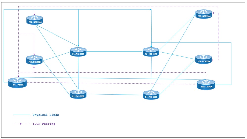
The physical topology of XYZ Networks is depicted in this figure. For the sake of simplicity, only 4 PE and 4 P nodes are shown. There are two RR nodes that act in clusters to provide redundancy.
Figure 11. Physical Topology
8.5. Layer 1 Design Details
In the generic layer 1 design, there is a Bundle Ethernet with at least two member links per bundle configured. For fast detection of link failure, choose BFD over the Bundle feature. The time interval can be ideally varied between 5-15 msec. It depends on the hardware capability to offload.
For BFD details, refer to https://www.cisco.com/c/en/us/td/docs/iosxr/ncs5500/routing/73x/b-routing-cg-ncs5500-73x/implementing-bfd.html. Note that this feature has to be configured only under the Bundle Ethernet interface and it is not required to configure it under IGP. The MTU size is fixed at 9216 with an aim to support up to 5 to 6 SR label-stack.
8.5.1. Configuration Templates
The BFD over Bundle configuration templates for all nodes is as shown here:
interface Bundle-Ether <Intf-Number>

 bfd address-family ipv4 timers start 60

 bfd address-family ipv4 timers nbr-unconfig 60

 bfd address-family ipv4 multiplier 3

 bfd address-family ipv4 destination <Connected-Intf-IP>

 bfd address-family ipv4 fast-detect

 bfd address-family ipv4 minimum-interval <Time in msec>

 mtu <Value as per requirement>

 ipv4 address <Intf IP> <Subnet Mask>>

 bundle minimum-active links 1

!
8.6. OSPF/SR-TE Design Overview
All OSPFv2 routers in the network are in Area 0 and so the network handles a single IGP domain.
Under router OSPF, segment routing is enabled and relevant Bundle Ethernet interfaces are configured. Likewise, under Bundle Interfaces, network type and fast reroute parameters are enabled. Most importantly a Loopback Interface is enabled in passive mode with Prefix-SID configured.
OSPF is a link-state protocol, so, it must be a priority to immediately identify the downlinks and create a backup path is necessary. To care for that, BFD over Bundle under Bundle Interface and TI-LFA FRR under OSPF is configured which keeps convergence time at 50 msec in case of fiber cut scenarios.
These sub-sections depict Normal and Failover Scenarios of the traffic paths in detail:
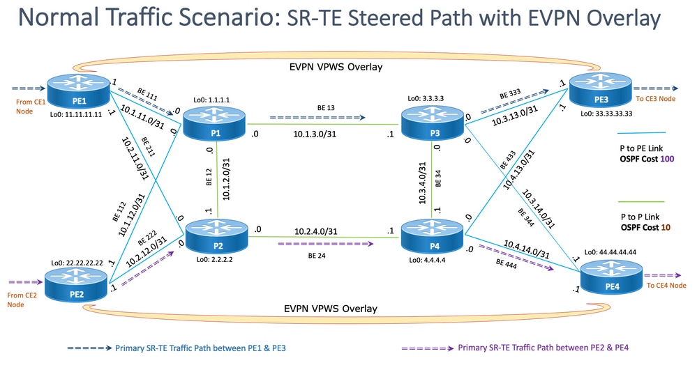
8.6.1. SR-TE Normal Traffic Scenario
To maintain a very strict primary path SR-TE policies are to be designed with end-to-end explicit paths between the source-destination traffic pairs mentioned earlier. Also, multiple preference candidate paths are needed within an SR-TE policy to provide provision for multiple failover scenarios.
This figure depicts the User Network details in alignment with the design blocks mentioned in sub-section 8.3.
- Links between PE to P and P to P nodes
- Loopback Addresses of all nodes
- Interface Addresses of all nodes
- SR-TE Steered Normal Traffic Path Direction
- EVPN Overlay between PE nodes
The RRs have been not shown intentionally to reduce clutter in the topology.
The links between PE and P have been marked with blue and the links between P and P have been marked with green color. The OSPF cost of PE-to-P links is 100 and the cost of P-to-P links is 10.
The primary SR-TE traffic flow has been marked with blue arrows between the PE1-PE3 pair and marked with violet arrows between the PE2-PE4 pair.
Figure 12. Topology Details

8.6.1.1. Configuration Templates
This sub-section contains the relevant configuration templates of OSPF/SR-TE for PE1 & PE2 nodes as given:
# PE1 Node: OSPF & SR-TE configs
router ospf CORE
nsr
distribute link-state Command to distribute OSPF database into SR-TE database
log adjacency changes
router-id <Router-ID-PE1> OSPF Router-ID
segment-routing mpls
nsf cisco
microloop avoidance segment-routing Command to enable microloop avoidance with TI-LFA
area 0
interface Bundle-Ether<Intf-Number> OSPF PE to P Link
cost 100 OSPF PE to P Metric
authentication keychain <Key-Chain> Command to enable OSPF Authentication per link
network point-to-point
fast-reroute per-prefix Commands to enable TI-LFA
fast-reroute per-prefix ti-lfa enable
fast-reroute per-prefix tiebreaker node-protecting index <Index-Value>
prefix-suppression
!
interface Loopback <Loopback-ID-PE1>
passive enable
prefix-sid index <SID-Index-Number1> OSPF Loopback Prefix SID
Note: To configure the Source-Address” command either GLOBALLY OR under POLICY. As default behavior, the source address under policy supersedes the global command.
The source address command under segment routing configuration as shown is needed in specific scenarios where, in the same PE, as the source of the SR-TE policy we need to choose one loopback address amongst multiple or when both ISIS and OSPF run with separate loopbacks, and we need to freeze on one of those. Otherwise in normal scenarios where there is only one IGP that runs with a unique loopback then source address configuration is optional.
segment-routing
global-block 16000 23999 Default SRGB Value (Need not be configured). Needs to be configured only if non-default value is assigned
local-block 15000 15999 Default SRLB Value (Need not be configured). Needs to be configured only if non-default value is assigned
traffic-eng
candidate-paths
all
source-address ipv4 <IGP-Source-Address> Configure SR-TE source address as OSPF loopback (Global Option)
!
!
segment-list name <SIDLIST1> Primary/Normal Path SID-LIST1
index <Index ID> mpls adjacency <Remote-IP-Address-Link1>
index <Index ID> mpls adjacency <Remote-IP-Address-Link2>
index <Index ID> mpls adjacency <Remote-IP-Address-Link3>
!
segment-list name <SIDLIST2> Primary Back Up Path SID-LIST2
index <Index ID> mpls adjacency <Remote-IP-Address-Link4>
index <Index ID> mpls adjacency <Remote-IP-Address-Link5>
index <Index ID> mpls adjacency <Remote-IP-Address-Link6>
!
segment-list name <SIDLIST3> Secondary Back Up Path SID-LIST3
index <Index ID> mpls adjacency <Remote-IP-Address-Link4>
index <Index ID> mpls adjacency <Remote-IP-Address-Link5>
index <Index ID> mpls adjacency <Remote-IP-Address-Link6>
!
policy <Pol-Name1>
source-address ipv4 <IGP-Source-Address> Configure SR-TE source address as OSPF loopback (Policy Specific Option)
color <Color-ID> end-point ipv4 <Destn-PE3>
candidate-paths
preference 50 Tertiary Back Up Path with least preference
dynamic
metric
type igp
!
!
!
preference 100 Secondary Back Up Path with 3rd highest preference
explicit segment-list <SIDLIST3>
!
!
preference 150 Primary Back Up Path with 2nd highest preference
explicit segment-list <SIDLIST2>
!
!
preference 200 Primary/Normal Path with highest preference (Active Path for PE1 in this scenario)
explicit segment-list <SIDLIST1>
!
!
!
!
!
!
# PE2 Node: OSPF & SR-TE configs
router ospf CORE
nsr
distribute link-state Command to distribute OSPF database into SR-TE database
log adjacency changes
router-id <Router-ID-PE2> OSPF Router-ID
segment-routing mpls
nsf cisco
microloop avoidance segment-routing Command to enable microloop avoidance with TI-LFA
area 0
interface Bundle-Ether<Intf-Number> OSPF PE to P Link
cost 100 OSPF PE to P Metric
authentication keychain <Key-Chain> Command to enable OSPF Authentication per link
network point-to-point
fast-reroute per-prefix Commands to enable TI-LFA
fast-reroute per-prefix ti-lfa enable
fast-reroute per-prefix tiebreaker node-protecting index <Index-Value>
prefix-suppression
!
interface Loopback <Loopback-ID-PE2>
passive enable
prefix-sid index <SID-Index-Number2> OSPF Loopback Prefix SID
Note: The optional source address, default SRGB, and SRLB commands have been removed.
segment-routing
traffic-eng
!
!
segment-list name <SIDLIST1> Primary/Normal Path SID-LIST1
index <Index ID> mpls adjacency <Remote-IP-Address-Link1>
index <Index ID> mpls adjacency <Remote-IP-Address-Link2>
index <Index ID> mpls adjacency <Remote-IP-Address-Link3>
!
segment-list name <SIDLIST2> Primary Back Up Path SID-LIST2
index <Index ID> mpls adjacency <Remote-IP-Address-Link4>
index <Index ID> mpls adjacency <Remote-IP-Address-Link5>
index <Index ID> mpls adjacency <Remote-IP-Address-Link6>
!
segment-list name <SIDLIST3> Secondary Back Up Path SID-LIST3
index <Index ID> mpls adjacency <Remote-IP-Address-Link4>
index <Index ID> mpls adjacency <Remote-IP-Address-Link5>
index <Index ID> mpls adjacency <Remote-IP-Address-Link6>
!
policy <Pol-Name1>
source-address ipv4 <IGP-Source-Address> Configure SR-TE source address as OSPF loopback (Policy Specific Option)
color <Color-ID> end-point ipv4 <Destn-PE4>
candidate-paths
preference 50 Tertiary Back Up Path with least preference
dynamic
metric
type igp
!
!
!
preference 100 Secondary Back Up Path with 3rd highest preference
explicit segment-list <SIDLIST3>
!
!
preference 150 Primary Back Up Path with 2nd highest preference
explicit segment-list <SIDLIST2>
!
!
preference 200 Primary/Normal Path with highest preference (Active Path for PE2 in this scenario)
explicit segment-list <SIDLIST1>
!
!
!
!
!
!
Note: In the previously mentioned solution, the explicit-hops of the segment-lists are based on IP addresses, since as mentioned here, explicit path SR-TE policy configuration based on “mpls label” the path validation does not work for remote link failure in 7.3.x
In case any remote link, apart from the local link of a PE node, fails still the path remains valid. This is as designed and cannot be modified till XR 7.5.x
# PE Node: SR-TE configs


router ospf <Process-Name>

 address-family ipv4 unicast

 area 0

  interface <Core BE Intf1>

  adjacency-sid absolute <Adj-SID1>

  interface <Core BE Intf2>

  adjacency-sid absolute < Adj-SID2>

  interface <Core BE Intf3>

  adjacency-sid absolute < Adj-SID3>


segment-routing

 traffic-eng

  policy <Pol-Name1>

   color <Color-ID> end-point ipv4 <Destn-PE>

   candidate-paths

    preference 10

     explicit segment-list <SIDLIST1>

     !

    preference 20

     dynamic

       metric

       type igp

     !

  segment-list name <SIDLIST1>

    index 10 mpls label <Adj-SID-Link1>

    index 20 mpls label <Adj-SID-Link2>

    index 30 mpls label <Adj-SID-Link3>
8.6.2. SR-TE for Failover Scenarios
To understand the traffic failover scenarios, one must take a close look at the primary path traffic under normal traffic conditions as mentioned in the topology diagram in the previous sub-section.
The primary objective in case of failover scenarios is to keep the traffic path disjointness to the maximum extent possible given the current topology infrastructure. The XYZ Network has strict requirements to administratively steer the traffic through specific nodes in backup paths so as to maintain maximum separation between the source-destination node pairs. This design is done to avoid the used links from overload and to keep minimum unused links.
These sub-sections show the various failover scenarios like single link, double link, single node and double node with the failover path that the traffic takes to maintain maximum disjointness.
8.6.3. Single Link Failover Scenario
This is the single link failure scenario where the local link between PE1 and P1 fails and the traffic takes a detour via the core P2 and P1 nodes. This is administratively steered via segment-list <SIDLIST1> which forms the primary backup path between PE1 and PE3 nodes
Figure 13. Single Link Failover Scenario
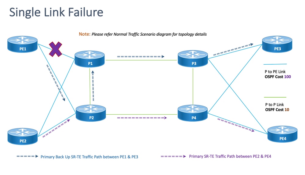
Disjointness: For single link failure, the number of common links shared is zero (0) as shown in the previous topology.
8.6.3.1. Configuration Templates
This sub-section contains the relevant configuration templates of OSPF/SR-TE for PE1 & PE2 nodes as given here:
Note: Router OSPF configuration templates of PE1 & PE2 are similar to the Normal Scenario.
# PE1 Node: OSPF & SR-TE configs
segment-routing
traffic-eng
!
!
segment-list name <SIDLIST1> Primary/Normal Path SID-LIST1
index <Index ID> mpls adjacency <Remote-IP-Address-Link1>
index <Index ID> mpls adjacency <Remote-IP-Address-Link2>
index <Index ID> mpls adjacency <Remote-IP-Address-Link3>
!
segment-list name <SIDLIST2> Primary Back Up Path SID-LIST2
index <Index ID> mpls adjacency <Remote-IP-Address-Link4>
index <Index ID> mpls adjacency <Remote-IP-Address-Link5>
index <Index ID> mpls adjacency <Remote-IP-Address-Link6>
!
segment-list name <SIDLIST3> Secondary Back Up Path SID-LIST3
index <Index ID> mpls adjacency <Remote-IP-Address-Link4>
index <Index ID> mpls adjacency <Remote-IP-Address-Link5>
index <Index ID> mpls adjacency <Remote-IP-Address-Link6>
!
policy <Pol-Name1>
source-address ipv4 <IGP-Source-Address> Configure SR-TE source address as OSPF loopback (Policy Specific Option)
color <Color-ID> end-point ipv4 <Destn-PE3>
candidate-paths
preference 50 Tertiary Back Up Path with least preference
dynamic
metric
type igp
!
!
!
preference 100 Secondary Back Up Path with 3rd highest preference
explicit segment-list <SIDLIST3>
!
!
preference 150 Primary Back Up Path with 2nd highest preference (Active Path for PE1 in this scenario)
explicit segment-list <SIDLIST2>
!
!
preference 200 Primary/Normal Path with highest preference
explicit segment-list <SIDLIST1>
!
!
!
!
!
!
Note: Router OSPF configuration templates of PE1 & PE2 are similar to the Normal Scenario.
# PE2 Node: OSPF & SR-TE configs
segment-routing
traffic-eng
!
!
segment-list name <SIDLIST1> Primary/Normal Path SID-LIST1
index <Index ID> mpls adjacency <Remote-IP-Address-Link1>
index <Index ID> mpls adjacency <Remote-IP-Address-Link2>
index <Index ID> mpls adjacency <Remote-IP-Address-Link3>
!
segment-list name <SIDLIST2> Primary Back Up Path SID-LIST2
index <Index ID> mpls adjacency <Remote-IP-Address-Link4>
index <Index ID> mpls adjacency <Remote-IP-Address-Link5>
index <Index ID> mpls adjacency <Remote-IP-Address-Link6>
!
segment-list name <SIDLIST3> Secondary Back Up Path SID-LIST3
index <Index ID> mpls adjacency <Remote-IP-Address-Link4>
index <Index ID> mpls adjacency <Remote-IP-Address-Link5>
index <Index ID> mpls adjacency <Remote-IP-Address-Link6>
!
policy <Pol-Name1>
source-address ipv4 <IGP-Source-Address> Configure SR-TE source address as OSPF loopback (Policy Specific Option)
color <Color-ID> end-point ipv4 <Destn-PE4>
candidate-paths
preference 50 Tertiary Back Up Path with least preference
dynamic
metric
type igp
!
!
!
preference 100 Secondary Back Up Path with 3rd highest preference
explicit segment-list <SIDLIST3>
!
!
preference 150 Primary Back Up Path with 2nd highest preference
explicit segment-list <SIDLIST2>
!
!
preference 200 Primary/Normal Path with highest preference (Active Path for PE2 in this scenario)
explicit segment-list <SIDLIST1>
!
!
!
!
!
!
8.6.4. Double Link Failover Scenario
This is the double link failure scenario where the local link between PE1 & P1 and the local link between PE2 & P2 fails. The traffic from PE1 takes a detour via the core P2 and P1 nodes and the traffic from PE2 takes a detour via the core P1 and P2 nodes.
These are administratively steered via respective segment-list <SIDLIST2> of PE1 & PE2 which form the secondary backup paths between PE1 & PE3 and PE2 & PE4 nodes respectively.
Figure 14. Double Link Failover Scenario
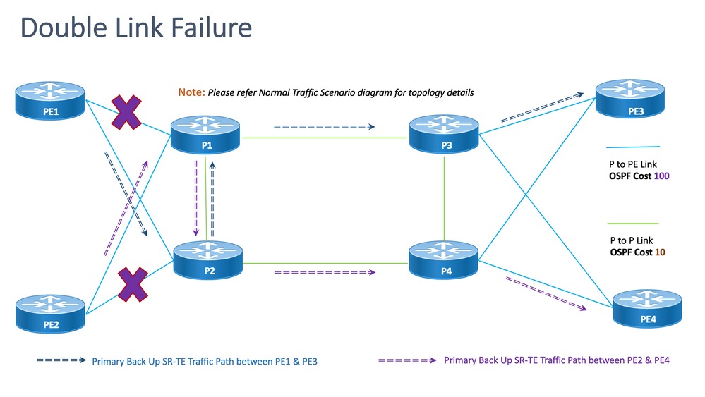
Disjointness: For double link failure, the number of common links shared is one (1) as shown in the previously mentioned topology.
8.6.4.1. Configuration Templates
This sub-section contains the relevant configuration templates of OSPF/SR-TE for PE1 & PE2 nodes as given here:
Note: Router OSPF configuration templates of PE1 & PE2 are similar to the Normal Scenario.
# PE1 Node: OSPF & SR-TE configs

#show run router ospf


router ospf CORE

 distribute link-state

 log adjacency changes

 router-id 11.11.11.11

 segment-routing mpls

 microloop avoidance segment-routing

 area 0

  interface Bundle-Ether11

   cost 100

   authentication keychain XYZ-CONT-PE1

   network point-to-point

   fast-reroute per-prefix

   fast-reroute per-prefix ti-lfa enable

   fast-reroute per-prefix tiebreaker node-protecting index 200

   prefix-suppression

  !

  interface Bundle-Ether12

   cost 100

   authentication keychain XYZ-CONT-PE1

   network point-to-point

   fast-reroute per-prefix

   fast-reroute per-prefix ti-lfa enable

   fast-reroute per-prefix tiebreaker node-protecting index 200

   prefix-suppression

  !

  interface Loopback0

   passive enable

   prefix-sid index 11

  !

 !

!
segment-routing
traffic-eng
!
!
segment-list name <SIDLIST1> Primary/Normal Path SID-LIST1
index <Index ID> mpls adjacency <Remote-IP-Address-Link1>
index <Index ID> mpls adjacency <Remote-IP-Address-Link2>
index <Index ID> mpls adjacency <Remote-IP-Address-Link3>
!
segment-list name <SIDLIST2> Primary Back Up Path SID-LIST2
index <Index ID> mpls adjacency <Remote-IP-Address-Link4>
index <Index ID> mpls adjacency <Remote-IP-Address-Link5>
index <Index ID> mpls adjacency <Remote-IP-Address-Link6>
!
segment-list name <SIDLIST3> Secondary Back Up Path SID-LIST3
index <Index ID> mpls adjacency <Remote-IP-Address-Link4>
index <Index ID> mpls adjacency <Remote-IP-Address-Link5>
index <Index ID> mpls adjacency <Remote-IP-Address-Link6>
!
policy <Pol-Name1>
source-address ipv4 <IGP-Source-Address> Configure SR-TE source address as OSPF loopback (Policy Specific Option)
color <Color-ID> end-point ipv4 <Destn-PE3>
candidate-paths
preference 50 Tertiary Back Up Path with least preference
dynamic
metric
type igp
!
!
!
preference 100 Secondary Back Up Path with 3rd highest preference
explicit segment-list <SIDLIST3>
!
!
preference 150 Primary Back Up Path with 2nd highest preference (Active Path for PE1 in this scenario)
explicit segment-list <SIDLIST2>
!
!
preference 200 Primary/Normal Path with highest preference
explicit segment-list <SIDLIST1>
!
!
!
!
!
!
Note: Router OSPF configuration templates of PE1 & PE2 are similar to the Normal Scenario.
# PE2 Node: OSPF & SR-TE configs
segment-routing
traffic-eng
!
!
segment-list name <SIDLIST1> Primary/Normal Path SID-LIST1
index <Index ID> mpls adjacency <Remote-IP-Address-Link1>
index <Index ID> mpls adjacency <Remote-IP-Address-Link2>
index <Index ID> mpls adjacency <Remote-IP-Address-Link3>
!
segment-list name <SIDLIST2> Primary Back Up Path SID-LIST2
index <Index ID> mpls adjacency <Remote-IP-Address-Link4>
index <Index ID> mpls adjacency <Remote-IP-Address-Link5>
index <Index ID> mpls adjacency <Remote-IP-Address-Link6>
!
segment-list name <SIDLIST3> Secondary Back Up Path SID-LIST3
index <Index ID> mpls adjacency <Remote-IP-Address-Link4>
index <Index ID> mpls adjacency <Remote-IP-Address-Link5>
index <Index ID> mpls adjacency <Remote-IP-Address-Link6>
!
policy <Pol-Name1>
source-address ipv4 <IGP-Source-Address> Configure SR-TE source address as OSPF loopback (Policy Specific Option)
color <Color-ID> end-point ipv4 <Destn-PE4>
candidate-paths
preference 50 Tertiary Back Up Path with least preference
dynamic
metric
type igp
!
!
!
preference 100 Secondary Back Up Path with 3rd highest preference
explicit segment-list <SIDLIST3>
!
!
preference 150 Primary Back Up Path with 2nd highest preference (Active Path for PE2 in this scenario)
explicit segment-list <SIDLIST2>
!
!
preference 200 Primary/Normal Path with highest preference
explicit segment-list <SIDLIST1>
!
!
!
!
!
!
8.6.5. Single Node Failover Scenario
This is the single node failure scenario where the node P1 fails and the traffic takes a detour via the core P2 and P4 nodes. This is administratively steered via segment-list <SIDLIST3> which forms the secondary backup path between PE1 and PE3 nodes.
The traffic between PE2 & PE4, however, remains the same as the primary path as shown in this topology.
Figure 15. Single Node Failover Scenario
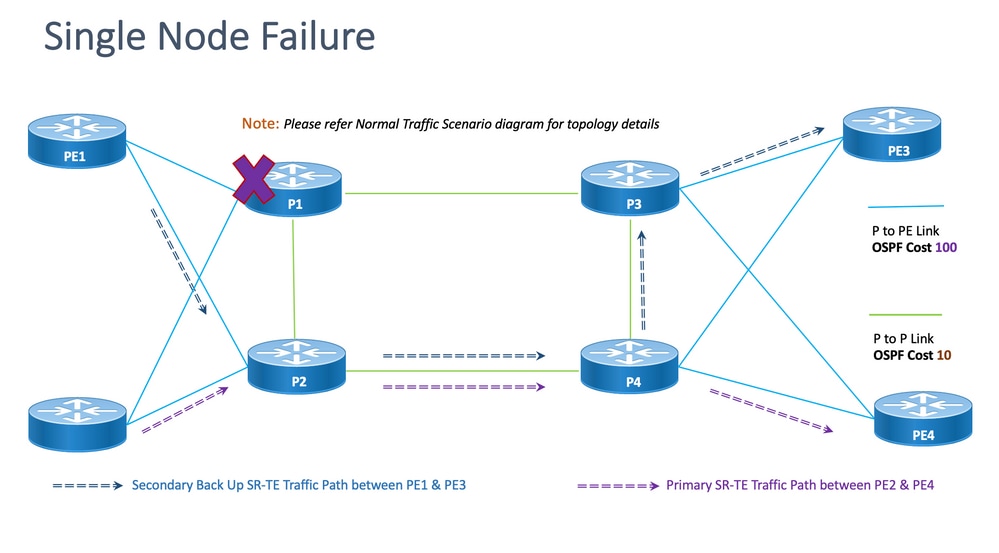
Disjointness: For single node failure, the number of common links shared is one (1) as shown in the previously mentioned topology.
8.6.5.1. Configuration Templates
This sub-section contains the relevant configuration templates of OSPF/SR-TE for PE1 & PE2 nodes as given:
Note: Router OSPF configuration templates of PE1 & PE2 are similar to the Normal Scenario.
segment-routing
traffic-eng
!
!
segment-list name <SIDLIST1> Primary/Normal Path SID-LIST1
index <Index ID> mpls adjacency <Remote-IP-Address-Link1>
index <Index ID> mpls adjacency <Remote-IP-Address-Link2>
index <Index ID> mpls adjacency <Remote-IP-Address-Link3>
!
segment-list name <SIDLIST2> Primary Back Up Path SID-LIST2
index <Index ID> mpls adjacency <Remote-IP-Address-Link4>
index <Index ID> mpls adjacency <Remote-IP-Address-Link5>
index <Index ID> mpls adjacency <Remote-IP-Address-Link6>
!
segment-list name <SIDLIST3> Secondary Back Up Path SID-LIST3
index <Index ID> mpls adjacency <Remote-IP-Address-Link4>
index <Index ID> mpls adjacency <Remote-IP-Address-Link5>
index <Index ID> mpls adjacency <Remote-IP-Address-Link6>
!
policy <Pol-Name1>
source-address ipv4 <IGP-Source-Address> Configure SR-TE source address as OSPF loopback (Policy Specific Option)
color <Color-ID> end-point ipv4 <Destn-PE3>
candidate-paths
preference 50 Tertiary Back Up Path with least preference
dynamic
metric
type igp
!
!
!
preference 100 Secondary Back Up Path with 3rd highest preference (Active Path for PE1 in this scenario)
explicit segment-list <SIDLIST3>
!
!
preference 150 Primary Back Up Path with 2nd highest preference
explicit segment-list <SIDLIST2>
!
!
preference 200 Primary/Normal Path with highest preference
explicit segment-list <SIDLIST1>
!
!
!
!
!
!
Note: Router OSPF configuration templates of PE1 & PE2 are similar to the Normal Scenario.
# PE2 Node: OSPF & SR-TE configs
segment-routing
traffic-eng
!
!
segment-list name <SIDLIST1> Primary/Normal Path SID-LIST1
index <Index ID> mpls adjacency <Remote-IP-Address-Link1>
index <Index ID> mpls adjacency <Remote-IP-Address-Link2>
index <Index ID> mpls adjacency <Remote-IP-Address-Link3>
!
segment-list name <SIDLIST2> Primary Back Up Path SID-LIST2
index <Index ID> mpls adjacency <Remote-IP-Address-Link4>
index <Index ID> mpls adjacency <Remote-IP-Address-Link5>
index <Index ID> mpls adjacency <Remote-IP-Address-Link6>
!
segment-list name <SIDLIST3> Secondary Back Up Path SID-LIST3
index <Index ID> mpls adjacency <Remote-IP-Address-Link4>
index <Index ID> mpls adjacency <Remote-IP-Address-Link5>
index <Index ID> mpls adjacency <Remote-IP-Address-Link6>
!
policy <Pol-Name1>
source-address ipv4 <IGP-Source-Address> Configure SR-TE source address as OSPF loopback (Policy Specific Option)
color <Color-ID> end-point ipv4 <Destn-PE4>
candidate-paths
preference 50 Tertiary Back Up Path with least preference
dynamic
metric
type igp
!
!
!
preference 100 Secondary Back Up Path with 3rd highest preference
explicit segment-list <SIDLIST3>
!
!
preference 150 Primary Back Up Path with 2nd highest preference
explicit segment-list <SIDLIST2>
!
!
preference 200 Primary/Normal Path with highest preference (Active Path for PE2 in this scenario)
explicit segment-list <SIDLIST1>
!
!
!
!
!
!
8.6.6. Double Node Failover Scenario
This is the double node failure scenario where the nodes P1 & P3 fail and the traffic takes a detour via the core P2 and P4 nodes. This is administratively steered via segment-list <SIDLIST3> which forms the secondary backup path between PE1 and PE3 nodes. Since the explicit paths are defined only for the previously mentioned 2 scenarios, here the dynamic IGP path forms the tertiary backup path and takes up the role of routing the traffic via the P2 & P4 nodes.
The traffic between PE2 & PE4, however, remains the same as the primary path as shown in this topology.
Figure 16. Double Node Failover Scenario.
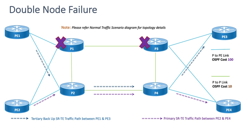
Disjointness: For double node failure, the number of common links shared is one (1) as shown in this topology.
8.6.6.1. Configuration Templates
This sub-section contains the relevant configuration templates of OSPF/SR-TE for PE1 & PE2 nodes as given:
Note: Router OSPF configuration templates of PE1 & PE2 are similar to the Normal Scenario.
# PE1 Node: OSPF & SR-TE configs
segment-routing
traffic-eng
!
!
segment-list name <SIDLIST1> Primary/Normal Path SID-LIST1
index <Index ID> mpls adjacency <Remote-IP-Address-Link1>
index <Index ID> mpls adjacency <Remote-IP-Address-Link2>
index <Index ID> mpls adjacency <Remote-IP-Address-Link3>
!
segment-list name <SIDLIST2> Primary Back Up Path SID-LIST2
index <Index ID> mpls adjacency <Remote-IP-Address-Link4>
index <Index ID> mpls adjacency <Remote-IP-Address-Link5>
index <Index ID> mpls adjacency <Remote-IP-Address-Link6>
!
segment-list name <SIDLIST3> Secondary Back Up Path SID-LIST3
index <Index ID> mpls adjacency <Remote-IP-Address-Link4>
index <Index ID> mpls adjacency <Remote-IP-Address-Link5>
index <Index ID> mpls adjacency <Remote-IP-Address-Link6>
!
policy <Pol-Name1>
source-address ipv4 <IGP-Source-Address> Configure SR-TE source address as OSPF loopback (Policy Specific Option)
color <Color-ID> end-point ipv4 <Destn-PE3>
candidate-paths
preference 50 Tertiary Back Up Path with least preference (Active Path for PE1 in this scenario -
Policy chooses Least Cost IGP Back Up Path in absence of Valid Explicit Path)
dynamic
metric
type igp
!
!
!
preference 100 Secondary Back Up Path with 3rd highest preference
explicit segment-list <SIDLIST3>
!
!
preference 150 Primary Back Up Path with 2nd highest preference
explicit segment-list <SIDLIST2>
!
!
preference 200 Primary/Normal Path with highest preference
explicit segment-list <SIDLIST1>
!
!
!
!
!
!
Note: Router OSPF configuration templates of PE1 & PE2 are similar to the Normal Scenario.
# PE2 Node: OSPF & SR-TE configs
segment-routing
traffic-eng
!
!
segment-list name <SIDLIST1> Primary/Normal Path SID-LIST1
index <Index ID> mpls adjacency <Remote-IP-Address-Link1>
index <Index ID> mpls adjacency <Remote-IP-Address-Link2>
index <Index ID> mpls adjacency <Remote-IP-Address-Link3>
!
segment-list name <SIDLIST2> Primary Back Up Path SID-LIST2
index <Index ID> mpls adjacency <Remote-IP-Address-Link4>
index <Index ID> mpls adjacency <Remote-IP-Address-Link5>
index <Index ID> mpls adjacency <Remote-IP-Address-Link6>
!
segment-list name <SIDLIST3> Secondary Back Up Path SID-LIST3
index <Index ID> mpls adjacency <Remote-IP-Address-Link4>
index <Index ID> mpls adjacency <Remote-IP-Address-Link5>
index <Index ID> mpls adjacency <Remote-IP-Address-Link6>
!
policy <Pol-Name1>
source-address ipv4 <IGP-Source-Address> Configure SR-TE source address as OSPF loopback (Policy Specific Option)
color <Color-ID> end-point ipv4 <Destn-PE4>
candidate-paths
preference 50 Tertiary Back Up Path with least preference
dynamic
metric
type igp
!
!
!
preference 100 Secondary Back Up Path with 3rd highest preference
explicit segment-list <SIDLIST3>
!
!
preference 150 Primary Back Up Path with 2nd highest preference
explicit segment-list <SIDLIST2>
!
!
preference 200 Primary/Normal Path with highest preference (Active Path for PE2 in this scenario)
explicit segment-list <SIDLIST1>
!
!
!
!
!
!
8.7. BGP/RR Design Overview
Border Gateway Protocol (BGP) is the protocol that makes core routing decisions on the Internet. It maintains a table of IP networks or "prefixes" which designate network reachability among autonomous systems (AS). It is described as a path vector protocol. BGP does not use traditional Interior Gateway Protocol (IGP) metrics, but makes routing decisions based on path, network policies, and/or rule sets. For this reason, it is more appropriately termed a reach-ability protocol rather than a routing protocol.
MP-BGP can be used to propagate IPv4, IPv6, VPNv4, VPNv6, EVPN, and Link-state prefixes through the network. This is done with a route reflector setup that forms iBGP neighbors with Core, aggregation, access devices, and SR-PCE devices.
Through the RR, BGP learned prefixes are propagated internally via iBGP. BGP routes are never redistributed into IGPs. The Route Reflectors are totally isolated from the data plane and are dedicated to control plane purposes.
8.7.1. Configuration Templates
This sub-section contains the relevant configuration templates for BGP/RR as shown:
# PE Node: Relevant BGP configs
router bgp <PE-ASN>
address-family l2vpn evpn
!
neighbor-group <RR-EVPN> Neighbor group of Route Reflector (RR)
remote-as <RR-ASN>
update-source <PE-Self-Loopback>
!
address-family l2vpn evpn AF L2VPN EVPN Neighborship with RR
maximum-prefix <PREFIX> <PERCENT> warning-only
!
address-family ipv4 rt-filter
!
neighbor <RR1-Loopback> Neighborship with RR1 using the above neighbor group
use neighbor-group <RR-EVPN>
neighbor <RR2-Loopback> Neighborship with RR2 using the above neighbor group
use neighbor-group <RR-EVPN>
# RR Nodes: Relevant BGP configs
router bgp <RR-ASN>
address-family l2vpn evpn
!
neighbor-group <PE-EVPN> Neighbor group of Provider Edge (PE)
remote-as <PE-ASN>
update-source <RR-Self-Loopback>
!
address-family l2vpn evpn AF L2VPN EVPN Neighborship with PE
route-reflector-client
!
address-family ipv4 rt-filter
!
neighbor <PE1-Loopback> Neighborship with PE1 using the above neighbor group
use neighbor-group <PE-EVPN>
neighbor <PE2-Loopback> Neighborship with PE2 using the above neighbor group
use neighbor-group <PE-EVPN>
8.8. Service Design Overview
This sub-section describes the EVPN VPWS Overlay Service along with the representation of the supported label stack and the configuration templates.
The EVPN-VPWS is a BGP control plane solution for point-to-point services. It implements the signalling and encapsulation techniques that establish an EVPN instance between a pair of PEs. It has the ability to forward traffic from one network to another without MAC lookup. The use of EVPN for VPWS eliminates the need for signalling single-segment and multi-segment PWs for point-to-point Ethernet services. The EVPN-VPWS technology works on IP and MPLS core; the IP core supports BGP and MPLS core for switching packets between the endpoints.
8.8.1. Label Stack Representation
The service aims to support up to 5 to 6 SR label-stack including SR transport labels, EVPN labels, and FAT labels for load balancing. This is the analyzed maximum number of labels in Normal Scenarios where traffic flows a through an Explicit Primary Path:
|
ADJ SID1 |
|
|
ADJ SID2 |
|
|
ADJ SID3 |
|
|
EVPN LABEL |
|
|
FLOW LABEL (S=1) |
This is the analyzed maximum number of labels in Failover Scenarios where traffic flows through backup Explicit Path or IGP defined dynamic backup path:
|
TI-LFA SID1 |
|
TI-LFA SID2 |
|
TI-LFA SID3 |
|
EVPN LABEL |
|
FLOW LABEL (S=1) |
8.8.2. Configuration Templates
This sub-section contains the relevant configuration templates for EVPN-VPWS as shown:
# PE Node: EVPN configs
evpn
evi <EVI-ID> Ethernet Virtual Identifier
bgp
rd <RD-Value>
route-target import <RT-Value>
route-target export <RT-Value>
!
load-balancing
flow-label static Generates bottom-most label (S=1) for load balancing between intra & inter BE end-to-end
!
!
interface <AC-Interface>
l2vpn
pw-class <PW-Class-Name1>
encapsulation mpls
preferred-path sr-te policy <Pol-Name1> Attaching SR-TE policy as the traffic path of EVPN
!
!
xconnect group <Group-Name>
p2p <P2P-Name>
interface <AC-Subinterface> EVPN Attachment Circuit Interface towards CE
neighbor evpn evi <EVI-ID> service <Service-ID> Service ID defined should match at both the end PEs
pw-class <PW-Class-Name1>
!
9. Sample Configuration and Show Commands
This final section contains the relevant configuration and show commands of PE nodes for the Normal Traffic Scenario only. These are captured here aligned with the parameters given in this figure as a reference which helps understand the configuration templates explained in previous sections.
9.1. Sample Configuration at PE Nodes
Figure 17. Topology with config parameters.
# PE1 Node: OSPF & SR-TE Config
#show run router ospf
router ospf CORE
distribute link-state Command to distribute OSPF database into SR-TE database
log adjacency changes
router-id 11.11.11.11 OSPF Router ID
segment-routing mpls
microloop avoidance segment-routing Command to enable microloop avoidance with TI-LFA
area 0
interface Bundle-Ether111 OSPF PE to P Link
cost 100 OSPF PE to P Metric
authentication keychain XYZ-CONT-PE1 Command to enable OSPF Authentication per link
network point-to-point
fast-reroute per-prefix Commands to enable TI-LFA
fast-reroute per-prefix ti-lfa enable
fast-reroute per-prefix tiebreaker node-protecting index 200
prefix-suppression
!
interface Bundle-Ether211
cost 100
authentication keychain XYZ-CONT-PE1
network point-to-point
fast-reroute per-prefix
fast-reroute per-prefix ti-lfa enable
fast-reroute per-prefix tiebreaker node-protecting index 200
prefix-suppression
!
interface Loopback0
passive enable
prefix-sid index 11 OSPF Loopback Prefix SID
!
!
!
#show run segment-routing
Sat Apr 16 23:22:42.727 UTC
segment-routing
traffic-eng
segment-list PrimaryPath Primary/Normal Path
index 10 mpls adjacency 10.1.11.0
index 20 mpls adjacency 10.1.3.1
index 30 mpls adjacency 10.3.13.1
!
segment-list PrimaryBackUpPath Primary Back Up Path
index 10 mpls adjacency 10.2.11.0
index 20 mpls adjacency 10.1.2.0
index 30 mpls adjacency 10.1.3.1
!
segment-list SecondaryBackUpPath Secondary Back Up Path
index 10 mpls adjacency 10.2.11.0
index 20 mpls adjacency 10.2.4.1
index 30 mpls adjacency 10.3.4.0
!
policy SR-TE_POLICY_PE1-to-PE3 SR-TE Policy Towards PE3
color 10 end-point ipv4 33.33.33.33 SR-TE Policy End-Point PE3 Loopback
candidate-paths
preference 50 Tertiary Back Up Dynamic IGP Path with 4th highest preference
dynamic
metric
type igp
!
!
!
preference 100 Secondary Back Up Path with 3rd highest preference
explicit segment-list SecondaryBackUpPath
!
!
preference 150 Primary Back Up Path with 2nd highest preference
explicit segment-list PrimaryBackUpPath
!
!
preference 200 Primary and Active Path with highest preference
explicit segment-list PrimaryPath
!
!
!
!
!
!
# PE2 Node: OSPF & SR-TE Config
#show run router ospf
router ospf CORE
distribute link-state Command to distribute OSPF database into SR-TE database
log adjacency changes
router-id 22.22.22.22 OSPF Router ID
segment-routing mpls
microloop avoidance segment-routing Command to enable microloop avoidance with TI-LFA
area 0
interface Bundle-Ether112 OSPF PE to P Link
cost 100 OSPF PE to P Metric
authentication keychain XYZ-CONT-PE2
network point-to-point
fast-reroute per-prefix Commands to enable TI-LFA
fast-reroute per-prefix ti-lfa enable
fast-reroute per-prefix tiebreaker node-protecting index 200
prefix-suppression
!
interface Bundle-Ether222
cost 100
authentication keychain XYZ-CONT-PE2 Command to enable OSPF Authentication per link
network point-to-point
fast-reroute per-prefix Commands to enable TI-LFA
fast-reroute per-prefix ti-lfa enable
fast-reroute per-prefix tiebreaker node-protecting index 200
prefix-suppression
!
interface Loopback0
passive enable
prefix-sid index 22 OSPF Loopback Prefix SID
!
!
!
#show run segment-routing
Sat Apr 16 23:22:42.727 UTC
segment-routing
traffic-eng
segment-list PrimaryPath Primary/Normal Path
index 10 mpls adjacency 10.2.12.0
index 20 mpls adjacency 10.2.4.1
index 30 mpls adjacency 10.4.14.1
!
segment-list PrimaryBackUpPath Primary Back Up Path
index 10 mpls adjacency 10.1.12.0
index 20 mpls adjacency 10.1.2.1
index 30 mpls adjacency 10.2.4.1
!
segment-list SecondaryBackUpPath Secondary Back Up Path
index 10 mpls adjacency 10.1.12.0
index 20 mpls adjacency 10.1.3.1
index 30 mpls adjacency 10.3.4.1
!
policy SR-TE_POLICY_PE2-to-PE4 SR-TE Policy Towards PE4
color 10 end-point ipv4 44.44.44.44 SR-TE Policy End-Point PE4 Loopback
candidate-paths
preference 50 Tertiary Back Up Dynamic IGP Path with 4th highest preference
dynamic
metric
type igp
!
!
!
preference 100 Secondary Back Up Path with 3rd highest preference
explicit segment-list SecondaryBackUpPath
!
!
preference 150 Primary Back Up Path with 2nd highest preference
explicit segment-list PrimaryBackUpPath
!
!
preference 200 Primary and Active Path with highest preference
explicit segment-list PrimaryPath
!
!
!
!
!
!
# PE1 Node: BGP Config
#show run router bgp
router bgp 64848
bgp router-id 11.11.11.11 BGP Router-ID
address-family l2vpn evpn
!
neighbor-group RR-EVPN
remote-as 64848
update-source Loopback0
address-family l2vpn evpn BGP AF L2VPN EVPN
!
!
neighbor 10.10.10.10 Neighbor Route Reflector
use neighbor-group RR-EVPN
!
!
# PE2 Node: BGP Config
#show run router bgp
router bgp 64848
bgp router-id 22.22.22.22 BGP Router-ID
address-family l2vpn evpn
!
neighbor-group RR-EVPN
remote-as 64848
update-source Loopback0
address-family l2vpn evpn BGP AF L2VPN EVPN
!
!
neighbor 10.10.10.10 Neighbor Route Reflector
use neighbor-group RR-EVPN
!
!
# PE1 Node: EVPN-VPWS Config
evpn
evi 100 Ethernet Virtual Identifier
bgp
rd 11:11
route-target import 100:100
route-target export 100:100
!
load-balancing Generates bottom-most label (S=1) for load balancing between intra & inter BE end-to-end
flow-label static
!
!
interface Bundle-Ether99 Interface Attachment Circuit
ethernet-segment
identifier type 0 00.00.00.00.00.00.00.00.00
!
!
!
# PE2 Node: EVPN-VPWS Config
evpn
evi 100 Ethernet Virtual Identifier
bgp
rd 11:11
route-target import 100:100
route-target export 100:100
!
load-balancing Generates bottom-most label (S=1) for load balancing between intra & inter BE end-to-end
flow-label static
!
!
interface Bundle-Ether99 Interface Attachment Circuit
ethernet-segment
identifier type 0 00.00.00.00.00.00.00.00.00
!
!
!
9.1. Relevant Show Commands at PE Nodes
# PE1 Node: SR-TE Show Command
#show segment-routing traffic-eng policy
Sat Apr 16 23:35:32.731 UTC
SR-TE policy database
---------------------
Color: 10, End-point: 33.33.33.33
Name: srte_c_10_ep_33.33.33.33
Status:
Admin: up Operational: up for 00:12:54 (since Apr 16 23:22:38.278)
Candidate-paths:
Preference: 200 (configuration) (active) Active Path (Path in use)
Name: SR-TE_POLICY_PE1-to-PE3
Requested BSID: dynamic
Protection Type: protected-preferred
Maximum SID Depth: 12
Explicit: segment-list PrimaryPath (valid) Only the Active Path shows valid
Weight: 1, Metric Type: TE
24007 [Adjacency-SID, 10.1.11.0 - 10.1.11.1]
24007 [Adjacency-SID, 10.1.3.0 - 10.1.3.1]
24005 [Adjacency-SID, 10.3.13.0 - 10.3.13.1]
Preference: 150 (configuration)
Name: SR-TE_POLICY_PE1-to-PE3
Requested BSID: dynamic
Protection Type: protected-preferred
Maximum SID Depth: 12
Explicit: segment-list PrimaryBackUpPath (invalid) All inactive paths show invalid
Weight: 1, Metric Type: TE
Preference: 100 (configuration)
Name: SR-TE_POLICY_PE1-to-PE3
Requested BSID: dynamic
Protection Type: protected-preferred
Maximum SID Depth: 12
Explicit: segment-list SecondaryBackUpPath (invalid)
Weight: 1, Metric Type: TE
Preference: 50 (configuration) All inactive paths show invalid
Name: SR-TE_POLICY_PE1-to-PE3
Requested BSID: dynamic
Protection Type: protected-preferred
Maximum SID Depth: 12
Dynamic (invalid)
Metric Type: IGP, Path Accumulated Metric: 0
Attributes:
Binding SID: 24020
Forward Class: Not Configured
Steering labeled-services disabled: no
Steering BGP disabled: no
IPv6 caps enable: yes
Invalidation drop enabled: no
# PE2 Node: SR-TE Show Command
#show segment-routing traffic-eng policy
Sat Apr 16 23:35:32.731 UTC
SR-TE policy database
---------------------
Color: 10, End-point: 44.44.44.44
Name: srte_c_10_ep_44.44.44.44
Status:
Admin: up Operational: up for 00:12:54 (since Apr 16 23:22:38.278)
Candidate-paths:
Preference: 200 (configuration) (active) Active Path (Path in use)
Name: SR-TE_POLICY_PE1-to-PE3
Requested BSID: dynamic
Protection Type: protected-preferred
Maximum SID Depth: 12
Explicit: segment-list PrimaryPath (valid) Only the Active Path shows valid
Weight: 1, Metric Type: TE
24007 [Adjacency-SID, 10.2.12.0 - 10.2.12.1]
24007 [Adjacency-SID, 10.2.4.0 - 10.2.4.1]
24005 [Adjacency-SID, 10.4.14.0 - 10.4.14.1]
Preference: 150 (configuration)
Name: SR-TE_POLICY_PE1-to-PE3
Requested BSID: dynamic
Protection Type: protected-preferred
Maximum SID Depth: 12
Explicit: segment-list PrimaryBackUpPath (invalid) All inactive paths show invalid
Weight: 1, Metric Type: TE
Preference: 100 (configuration)
Name: SR-TE_POLICY_PE1-to-PE3
Requested BSID: dynamic
Protection Type: protected-preferred
Maximum SID Depth: 12
Explicit: segment-list SecondaryBackUpPath (invalid)
Weight: 1, Metric Type: TE
Preference: 50 (configuration) All inactive paths show invalid
Name: SR-TE_POLICY_PE1-to-PE3
Requested BSID: dynamic
Protection Type: protected-preferred
Maximum SID Depth: 12
Dynamic (invalid)
Metric Type: IGP, Path Accumulated Metric: 0
Attributes:
Binding SID: 24020
Forward Class: Not Configured
Steering labeled-services disabled: no
Steering BGP disabled: no
IPv6 caps enable: yes
Invalidation drop enabled: no
# PE1 Node: BGP Show Command


#show bgp l2vpn evpn summary

Sun Apr 17 07:16:23.574 UTC


Address Family: L2VPN EVPN

--------------------------


BGP router identifier 11.11.11.11, local AS number 64848

BGP generic scan interval 60 secs

Non-stop routing is enabled

BGP table state: Active

Table ID: 0x0   RD version: 0

BGP main routing table version 25

BGP NSR Initial initsync version 1 (Reached)

BGP NSR/ISSU Sync-Group versions 25/0

BGP scan interval 60 secs


BGP is operating in STANDALONE mode.


Process       RcvTblVer   bRIB/RIB   LabelVer  ImportVer  SendTblVer  StandbyVer

Speaker              25         25         25         25          25          25


Neighbor        Spk    AS MsgRcvd MsgSent   TblVer  InQ OutQ  Up/Down  St/PfxRcd

10.10.10.10      0  64848    9500    9484       25    0    0    5d16h          1


# PE2 Node: BGP Show Command


#show bgp l2vpn evpn summary

Sun Apr 17 07:16:23.574 UTC


Address Family: L2VPN EVPN

--------------------------


BGP router identifier 22.22.22.22, local AS number 64848

BGP generic scan interval 60 secs

Non-stop routing is enabled

BGP table state: Active

Table ID: 0x0   RD version: 0

BGP main routing table version 25

BGP NSR Initial initsync version 1 (Reached)

BGP NSR/ISSU Sync-Group versions 25/0

BGP scan interval 60 secs
BGP operates in STANDALONE mode.
Process       RcvTblVer   bRIB/RIB   LabelVer  ImportVer  SendTblVer  StandbyVer

Speaker              25         25         25         25          25          25


Neighbor        Spk    AS MsgRcvd MsgSent   TblVer  InQ OutQ  Up/Down  St/PfxRcd

10.10.10.10      0  64848    9500    9484       25    0    0    5d16h          1
Troubleshoot
There is currently no specific troubleshooting information available for this configuration.
Related Information
- https://www.cisco.com/c/en/us/td/docs/routers/asr9000/software/asr9k-r7-5/segment-routing/configuration/guide/b-segment-routing-cg-asr9000-75x/about-segment-routing.html
- https://www.cisco.com/c/en/us/td/docs/routers/asr9000/software/asr9k-r7-5/lxvpn/configuration/guide/b-l2vpn-cg-asr9000-75x/evpn-features.html
- Technical Support & Documentation - Cisco Systems
Revision History
| Revision | Publish Date | Comments |
|---|---|---|
1.0 |
01-Jul-2022 |
Initial Release |
Contributed by Cisco Engineers
- Abhijit SarkarCisco Advanced Services
 Feedback
Contact Cisco
- Open a Support Case

- (Requires a Cisco Service Contract)