Unified Secure Policy and Segmentation: Consistent Policy and Segmentation Across Networks
Available Languages
Bias-Free Language
The documentation set for this product strives to use bias-free language. For the purposes of this documentation set, bias-free is defined as language that does not imply discrimination based on age, disability, gender, racial identity, ethnic identity, sexual orientation, socioeconomic status, and intersectionality. Exceptions may be present in the documentation due to language that is hardcoded in the user interfaces of the product software, language used based on RFP documentation, or language that is used by a referenced third-party product. Learn more about how Cisco is using Inclusive Language.
This document provides information about how to deploy a consistent, repeatable, and reusable segmented group-based policy environment for campus, remote access, and work-from-anywhere users from an architecture standpoint. This paper defines an architectural design approach to make the solution repeatable and maximize the benefits of a unified policy model across networks.
Disclaimer: Configuration constructs are not included in this paper, which is in a purely reference format for designing solutions for policy flow and segmentation.
This paper discusses the following:
● Operational challenges that customers face when dealing with policy and segmentation, especially with multiple networks that don’t interoperate in a large IT enterprise environment.
● Use of consistent and repeatable policy and segmentation for users over RAVPN and campus networks, and alternatives to home office networks, including Office Extend Access Points (OEAP) deployments.
● Use of a common directory service to authenticate users for consistent identification.
● Policy enforcement verification to ensure that traffic is being segmented and resources secured at every entry point.
● Leverage Cisco Platform Exchange Grid (pxGrid) to share a single framework to derive contextual information for the connections on the network and take advantage of actionable insights.
Prior knowledge of these topics is desirable to understand the design better:
● ASA configuration and Secure Group-based (SG-based) firewall concepts
● Remote access VPN configuration on the ASA
● Wireless (Office Extend Access Points [OEAP])
● Cisco ISE and segmentation services on wired and wireless networks
● Basic knowledge of pxGrid
● Segmentation designs for campus network
The design requirement is to utilize and leverage the segmentation policy that is already defined in a current campus network. Usually, in a segmented access scenario, “a project” is never in favor of changing the IP subnets that are already allowed
i
nto a customer's firewall to allow incoming traffic. Apart from this, there are challenges around overlapping CIDR subnets, which can cause undue administration overheads. The flow of traffic is designed in such a way that all the gateway requirements, such as NAT and IP subnets that are allowed at the exit perimeter project router or firewall will not require a change, in most cases. The gateway router and the VPN headend should be sized to take the load of SG-based PBR and NAT traffic. For smaller setups, the gateway functionality can be hosted with the ASA VPN headend, but with sizing and traffic conditions taken into consideration.
Other key asks are usually centred around the following:
● Being able to use the existing Cisco ISE for extending authentication and authorization for Remote Access VPN (RAVPN) and campus users.
● Scalable Group Tag (SGT) classification for VPN users.
● Consistent policy for users over RAVPN or any other deployment for home office wired or wireless networks and on-campus networks.
● Common directory service to authenticate users for consistent identification.
● Varied policy enforcement to ensure that traffic is being segmented and resources are secure.
The design framework was developed based on the requirements and use cases put forward by IT-enabled Service Provider customers to reuse the existing policy and segmentation model for any part of a network, including work-from-anywhere or home office network setups. IT and ITeS customers use a common term called Offshore Development Center (ODC) to refer to these segmented project environments.
The policy and segmentation requirements are often agile, and every project (commonly referred to as segmented or ODC environment) of these customers have different segmentation requirements for each project. Each network can sometimes be so complex that they can be referred to as a subset network within a large network arena.
The key objective was to define a policy once and reuse the same in every island in these networks, including RAVPN and extranet segments. This scenario can be applied to any major enterprise where segmented access with a unified policy is a requirement.
Note: While drafting this design, we have assumed that the entire network is end-to-end on Cisco devices, which brings in the goodness of all the integration and multi-domain capabilities. However, the design construct itself is generic and reusable, considering that the policy components are defined in the Cisco ISE policy engine, and third-party devices can derive and make use of the SGT information from Cisco ISE to define a segmentation policy, and subsequently use this policy to classify, propagate, and enforce these tags in an environment.
Some of the key highlights of this design are:
● Secure, policy-based automation and segmentation: Cisco ISE enables policy-based, automated network enforcement for access, security, and monitoring across all network domains. Instead of defining a policy separately for LAN, wireless LAN, and WAN, including RAVPN, it is defined only once, and applied to all these domains consistently.
● Complete network policy visibility: The entire wired, wireless, and RAVPN network can be viewed to provide deep visibility into traffic flow and derive contextual information to take the appropriate action.
● Fast and easy service enablement: Quickly enable services through Cisco Wireless Controller-based abstraction and open APIs, with fabric-aware security across a services ecosystem.
● Reduced network provisioning time: Simple design workflows that follow Cisco best practices, so that you can define the policy once and it takes effect everywhere, including a home office environment.
● Improved time to resolution: Obtain deep insights into users’ behavior, application performance, and threats, especially in a remote working environment.
● Risk containment: Enhance the network to act as both a sensor and enforcer – all the way from the clients to the applications - no matter where the clients access the network from. Contain risk through integrated security services that rapidly detect and mitigate threats.
In the light of the requirements described above, the following have been explored:
● RAVPN-SGT inline classification
● OEAP Remote access and using SGT SSID classification
The first method is a traditional RAVPN setup in which SGT segmentation is done using inline tagging, and tags are then propagated and enforced at the destination.
The second method can be considered for SOHO access for executives or senior management to maintain the right balance between security and flexibility. Note that in this method, each home user will have to be provided with hardware (an AP). Thus, logistics and inventory management should be taken into consideration in the context of the second method.
RAVPN-SGT Inline Classification
The SGT Inline Tagging feature allows ASA to receive tagged frames and send them. This way, ASA can be easily integrated within the segmented domain without the need to use the SGT Exchange Protocol (SXP).
While logging into an Enterprise network, remote VPN users connect using an SSL or an IPSec tunnel with the ASA VPN head. Users are authenticated through 802.1x, and based on the users' project group or Active Directory (AD) group, the tag assignment takes place. In the example displayed in the illustration below, a user belongs to Project A and is assigned an SGT Tag 10 (Project A). There is another user who follows the same mechanism to connect, but is based on the 802.1x identity verification, and is assigned a different tag, for example, SGT Tag 11 (Project B).
Traffic classification is performed by ASA with the use of the SGT assignment locally downloaded from Cisco ISE. ASA can also have an SG-based Firewall (SGFW) configured on the inside interface that allows the traffic initiated from one ODC to another, depending on specific segmentation requirements.
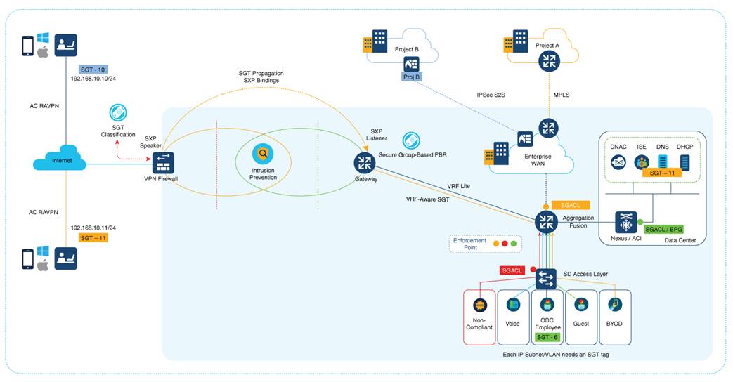
Note: ASA can also have SGFW controlling the traffic that comes from a remote VPN user. For example, traffic between a remote VPN user with SGT 10 and SGT 11 can be controlled through SGFW.
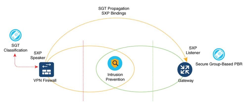
The traffic then heads to the gateway router through SXP reflection in order to facilitate IP-SGT mapping for VPN users. This is a single-hop SXP connection in most setups. However, depending on the number of devices that are set up, such as Load Balancers and IPS/IDS in the perimeter, a multi-hop SXP can also be looked at for implementation. SXP uses a transport layer. The requirement is for TCP 64999 to be open for connection initiation. In this flow, ASA is the SXP Speaker (Initiator), and the gateway router is the SXP listener (Receiver).
IP-SGT binding information is the basis for policy enforcement and forwarding. This enables the download of the appropriate policy for SGTs. When enforcement is applied on the devices’ egress interface, Source SGTs (S-SGT) or Destination Group Tags (DGT) that classify user traffic are used to make a permit or deny decision. Enforcements that are closest to the classification point conserve bandwidth. However, there may not be enough information available to decide. Therefore, enforcements are typically done closer to the destination.
Enforcement should be applied only by trusted devices that adhere to the following requirements:
● Authenticated and authorized by Cisco DNA Center
● Secure communications established with Cisco ISE
● SGFW rules defined on FWs or SG-based PBR on the SGT information pushed from Cisco ISE
The gateway router can, in turn, act as a NAT device that maps each segment to a specific VRF. After mapping is done, the SG-based PBR takes the routing decision to the specific sub-interface, which translates the IP to the corresponding segment-allocated pool on that sub-interface. In case of an SD-Access mapping, this gateway router can have a one-to-one mapping of VRFs-to-VN on the fusion router that again acts as an enforcement point.
In the case of a Data Center with ACI fabric, this IP-SGT table can be carried forward to an L3 for enforcement in the ACI domain right up to the DC services where the workloads reside. If the SGT needs to be propagated to a remote site, the gateway router can be mapped to a corresponding SD-WAN service VPN to get the traffic across to a remote site where IP-SGT mapping can be reimposed using SXP reflection, and enforcement can be achieved at the egress destination.
Configuration Assistance
SGT inline tagging in ASA:
OEAP Remote Access Using SGT SSID Classification
An OEAP provides secure communications from a Cisco Wireless Controller to a Cisco AP at a remote location, seamlessly extending the corporate WLAN over the Internet to an employee's residence. The user's experience at the home office is the same as it would be at a corporate office. Datagram Transport Layer Security (DTLS) encryption between the AP and the Cisco Wireless Controller ensures that all communications have the highest level of security.
The following figure shows a typical OEAP setup:
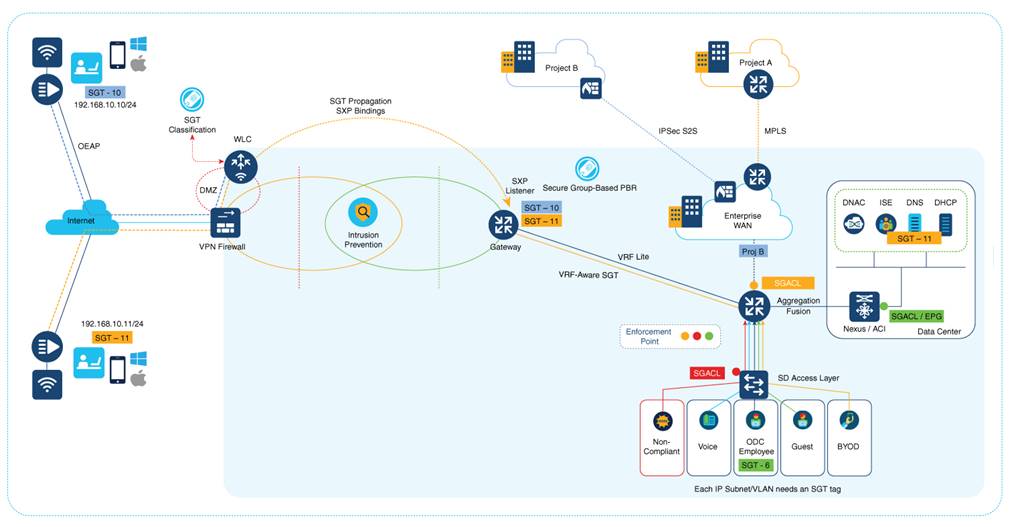
Cisco OEAPs are designed to work behind a router or another gateway device that uses NAT. NAT allows a device, such as a router, to act as an agent between the Internet (public) and a personal network (private), enabling an entire group of computers to be represented by a single public IP address. There is no limit to the number of Cisco OEAPs that you can deploy behind a NAT device.
Caution: All OEAPs should be in the same AP group, and that group should contain no more than 15 WLANs. A Cisco Wireless Controller with OEAPs in an AP group publishes only up to 15 WLANs to each connected OEAP because the Cisco Wireless Controller reserves one WLAN for the personal SSID.
The Cisco Wireless Controller requires a public routable IP so that remote APs can reach the Cisco Wireless Controller from their home network. Ideally, the Cisco Wireless Controller is placed in the DMZ. The public IP address can be added as a NAT IP Cisco Wireless Controller on the Cisco Wireless Controller management interface.
Some ports that are used for CAPWAP, RADIUS, TACACS+, NTP, and FTP, must be opened in the firewall because the OEAP Cisco Wireless Controllers that are located in the DMZ need to communicate with remote APs.
SXPv4 on AP
The Cisco Wireless Controller supports the SXPv2 Speaker mode to propagate IP-to-SGT bindings to neighboring devices. APs support SXPv4 for the Listener and Speaker modes.
CTS PAC Provisioning and Device Enrolment
Any device that participates in the CTS network requires it to be authenticated and trusted. To facilitate the authentication process, new devices that are connected to the CTS network undergo an enrolment process wherein a device obtains the credentials that are specifically needed for CTS device authentication and obtains general CTS environment information. Cisco Wireless Controller device enrolment is initiated by the Cisco Wireless Controller itself as part of PAC provisioning with Cisco ISE.
Inline Tagging
The inline tagging functionality is a transport mechanism by which a Cisco Wireless Controller or an AP understand and propagate the Source SGT (S-SGT). For centrally switched packets, the Cisco Wireless Controller performs inline tagging for all the packets sourced from wireless clients that reside in the Cisco Wireless Controller by tagging it with the Cisco Meta Data (CMD) tag. SGACL enforcement occurs in the corresponding AP.
A personal SSID can also be configured on an OEAP, and home users can use the same AP to connect for their home use. Note that the traffic from the personal SSID is not passed through the DTLS tunnel.
Remote LAN (RLAN)
Additionally, an access method called Remote LAN (RLAN) can be configured. An RLAN is used for authenticating wired clients using the Cisco Wireless Controller. After a wired client successfully joins the Cisco Wireless Controller, the LAN ports switch the traffic between the central or local switching modes. The traffic from the wired clients is treated as wireless client traffic. The RLAN in the AP sends an authentication request to authenticate the corresponding wired client. The authentication of wired clients in an RLAN is similar to the central authenticated wireless client. Local EAP is used for RLAN client authentication in the example provided in this document. Note that local EAP configuration must be enabled on the Cisco Wireless Controller to configure authentication and authorization methods, local EAP profiles, and local credentials.
Configuration Assistance
A lot of resources are already available with regard to the configuration. See the following video tutorial to configure the OEAP mode in Cisco AireOS controllers:
https://www.youtube.com/watch?v=MfdemAD0vos
Configuration of OEAP and RLAN on Cisco 9800 Series Wireless Controllers:
Wireless Segmentation deployment is explained in the following document. The classification and propagation method is what is needed for an OEAP deployment. The enforcement is carried out in the inner tiers of a campus environment.
The scenario described in this document is applicable for consistent policy enforcement for SOHO and work-from-anywhere users. There is no one way to do it. However, the scenario described here brings with it the goodness of an integrated Cisco security and IBN architecture along with strong segmentation and zero trust architecture. A lot of this design can be assimilated into existing setups to have the segmentation policies extended to RAVPN or OEAP users.