Configure Cisco Intersight Managed Mode for FlexPod and Deploy Red Hat Enterprise Linux
Available Languages
Bias-Free Language
The documentation set for this product strives to use bias-free language. For the purposes of this documentation set, bias-free is defined as language that does not imply discrimination based on age, disability, gender, racial identity, ethnic identity, sexual orientation, socioeconomic status, and intersectionality. Exceptions may be present in the documentation due to language that is hardcoded in the user interfaces of the product software, language used based on RFP documentation, or language that is used by a referenced third-party product. Learn more about how Cisco is using Inclusive Language.
This document presents the new Cisco Intersight™ Managed Mode (IMM) strategies, constructs, policies, and workflow involved in deploying the Cisco Unified Computing System™ (Cisco UCS®) with SAN boot (iSCSI and Fibre Channel) in a FlexPod Datacenter environment and details steps to install Red Hat Enterprise Linux 8. It also describes automated provisioning of solution using Terraform infrastructure as code.
The FlexPod solution delivers an integrated architecture that incorporates compute, storage, and network design best practices to reduce IT risks by validating the integrated architecture and helping ensure compatibility among the components. The solution addresses IT challenges by providing documented design and deployment guidance and solution support that can be used in various stages—in the planning, design, and implementation—of a deployment.
The Cisco Intersight™ platform is a management solution delivered as a service with embedded analytics for Cisco® and third-party IT infrastructures. Cisco Intersight managed mode (also referred to as Cisco IMM or Intersight managed mode) is a new implementation of concepts previously introduced with Cisco UCS® Manager and moves ownership of the policy model into the Cisco Intersight platform. The Cisco Unified Computing System™ (Cisco UCS) functions previously configured in a FlexPod environment using Cisco UCS Manager will now be delivered through the Cisco Intersight portal, which provides global visibility into the infrastructure health and status along with advanced management and support capabilities.
This document helps Cisco customers and business partners with the new Cisco Intersight managed mode strategies, constructs, policies, and workflow involved in deploying Cisco UCS with SAN boot in a FlexPod Datacenter environment and describes steps to install Red Hat Enterprise Linux (RHEL) 8.3. It details SAN boot configuration for both Fibre Channel and iSCSI boot scenarios. It also describes automated provisioning of solution using Terraform infrastructure as code.
Although the focus of this document is the Cisco UCS and Cisco Intersight managed mode platforms, customers interested in understanding FlexPod design and deployment details, including configuration of other elements of design and associated best practices, should refer to Cisco Validated Designs for FlexPod Datacenter at https://www.cisco.com/c/en/us/solutions/design-zone/data-center-design-guides/flexpod-design-guides.html.
This section provides an overview of the Cisco Intersight and FlexPod platforms.
Cisco Intersight overview
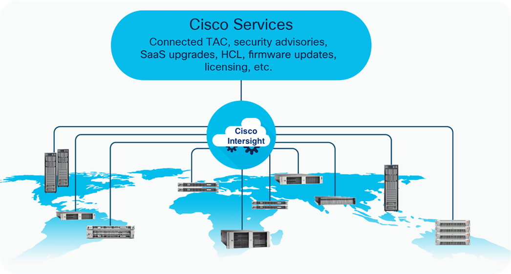
The Cisco Intersight platform is a software-as-a-service (SaaS) infrastructure lifecycle management platform that delivers simplified configuration, deployment, maintenance, and support. With the Cisco Intersight platform, customers get all the benefits of SaaS delivery and the full lifecycle management Cisco Intersight connected distributed servers and third-party storage systems such as NetApp across data centers, remote sites, branch offices, and edge environments (Figure 1).
The Cisco Intersight platform is designed to be modular, so customers can adopt services based on their individual requirements. The platform significantly simplifies IT operations by bridging applications with infrastructure, providing visibility and management from bare-metal servers and hypervisors to serverless applications, thereby reducing costs and mitigating risk. This unified SaaS platform uses a unified OpenAPI design that natively integrates with the third-party platforms and tools.
Cisco Intersight overview
The main benefits of Cisco Intersight infrastructure services are summarized here:
● Simplify daily operations by automating many daily manual tasks.
● Combine the convenience of a SaaS platform with the capability to connect from anywhere and manage infrastructure through a browser or mobile app.
● Stay ahead of problems and accelerate trouble resolution through advanced support capabilities.
● Gain global visibility of infrastructure health and status along with advanced management and support capabilities.
● Upgrade to add workload optimization and Kubernetes services when needed.
Cisco Intersight managed mode
Cisco Intersight managed mode is a new architecture that manages Cisco UCS fabric interconnected systems through a Redfish-based standard model. Cisco Intersight managed mode unifies the capabilities of Cisco UCS and the cloud-based flexibility of the Cisco Intersight platform, thus unifying the management experience for both standalone and fabric interconnect–attached systems. The Cisco Intersight management model standardizes policy and operation management for fourth-generation fabric interconnects and Cisco UCS M5 servers.
You can choose between the native Cisco UCS Manager managed mode and Cisco Intersight managed mode for fabric-attached Cisco UCS deployments during initial setup of the fabric interconnects or in a running system. The latter option is disruptive and negatively affects the endpoints and the existing configurations. If you choose to switch back to Cisco UCS Manager mode from Cisco Intersight managed mode, an option is provided to restore from a full-state Cisco UCS Manager backup.
Cisco Intersight Connected Virtual Appliance and Private Virtual Appliance
In addition to the SaaS deployment model running on Intersight.com, on-premises options can be purchased separately. The Cisco Intersight Connected Virtual Appliance and Cisco Intersight Private Virtual Appliance are available for organizations that have additional data locality or security requirements for managing systems. The Cisco Intersight Connected Virtual Appliance delivers the management features of the Cisco Intersight platform in an easy-to-deploy VMware Open Virtualization Appliance (OVA) or Microsoft Hyper-V Server virtual machine that allows you to control the system details that leave your premises. The Cisco Intersight Private Virtual Appliance is provided in a form factor specifically designed for users who operate in disconnected (air gap) environments. The Private Virtual Appliance requires no connection to public networks or back to Cisco to operate. At this time, Cisco Intersight managed mode configuration is available only through the Cisco Intersight SaaS platform and Connected Virtual Appliance.
FlexPod Datacenter overview
Customers seeking to deploy applications using a shared data center infrastructure face several challenges. A recurring infrastructure challenge is achieving the required levels of IT agility and efficiency to effectively meet the organization’s business objectives. Addressing these challenges requires an optimal solution with the following main characteristics:
● Availability: Help ensure that applications and services are available at all times, with no single point of failure.
● Flexibility: Support new services without requiring changes to the underlying infrastructure.
● Efficiency: Facilitate efficient operation of the infrastructure through reusable policies.
● Manageability: Facilitate ease of deployment and ongoing management, reducing operating costs.
● Scalability: Support easy expansion and growth, providing significant investment protection.
● Compatibility: Reduce risk by helping ensure compatibility of integrated components.
Cisco and NetApp have partnered to deliver a series of FlexPod solutions that enable strategic data center platforms with these characteristics. FlexPod delivers an integrated architecture that incorporates compute, storage, and network design best practices, reducing IT risks by validating the integrated architecture to help ensure compatibility among the system components.
FlexPod architecture can "flex" the environment to suit a customer's requirements. A FlexPod deployment can easily be scaled as compute, network, or storage requirements and or demands change. The unit can be scaled both up (adding resources to a FlexPod unit) and out (adding more FlexPod units). This wire-once fully validated architecture is highly resilient and cost effective and reduces customer risk.
FlexPod components
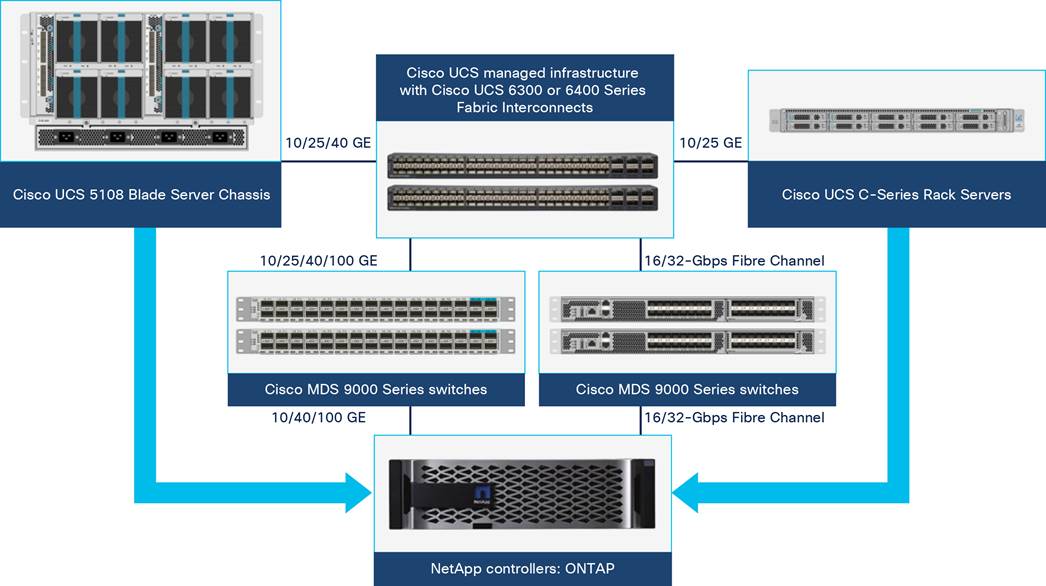
FlexPod architecture includes the following core components (Figure 2):
● Cisco UCS
● Cisco Nexus® Family switches
● Cisco MDS Family switches
● NetApp AFF/FAS storage systems
FlexPod Datacenter components
All the FlexPod components have been integrated so that customers can deploy the solution quickly and economically while eliminating many of the risks associated with researching, designing, building, and deploying similar solutions from the foundation. One of the main benefits of FlexPod is its ability to maintain consistency at scale. Each of the component families shown in Figure 2 (Cisco UCS, Cisco Nexus, Cisco MDS, and NetApp controllers) offers platform and resource options to scale the infrastructure up or down while supporting the same features and functions that are required under the configuration and connectivity best practices of FlexPod.
This section discusses the infrastructure setup, software and hardware requirements, and some of the design details of the Cisco Intersight managed mode deployment model. Specific hardware and software requirements must be followed to configure Cisco UCS using Cisco Intersight managed mode. The selection of FlexPod infrastructure components presented here closely aligns with Cisco Intersight managed mode requirements. This section does not cover the design details of FlexPod components such as Cisco Nexus and Cisco MDS switches and NetApp storage systems because their design and configuration conform to various Cisco Validated Designs for FlexPod and are covered widely elsewhere. This document focuses on the design elements of the new Cisco Intersight managed mode configuration.
Cisco Intersight managed mode enables complete configuration of multiple Cisco UCS domains and servers directly from the Cisco Intersight platform. Cisco Intersight managed mode introduces a new implementation of concepts previously introduced with Cisco UCS Manager and moves ownership of the policy model into Cisco Intersight. Fabric configuration in Cisco Intersight is first set up by deploying a Cisco UCS domain profile that encompasses all the policies related to the configuration of the switches and then associating it with server profiles. A Cisco UCS domain profile configures a fabric interconnect pair through reusable policies, simplifies the deployment of fabric interconnect pairs, allows configuration of ports and port channels, and configures the VLANs and VSANs in the network. Hence, policies, VLANs, and VSANs are created in-advance and built into a server profile. Then the server profile is assigned and deployed to a Cisco Intersight discovered Cisco UCS B-Series Blade Server or managed Cisco UCS C-Series Rack Server.
During initial fabric interconnect setup for a fabric-attached Cisco UCS deployment, customers can choose to deploy fabric interconnects and Cisco UCS in the native Cisco UCS Manager managed mode or in the new Cisco Intersight managed mode. This document discusses Cisco UCS deployment using Cisco Intersight managed mode, and all the configuration steps are performed using the Cisco Intersight SaaS platform.
Before setting up Cisco Intersight managed mode, review the supported hardware, software, and licensing requirements that follow.
Supported hardware for Cisco Intersight managed mode
The hardware listed in Table 1 is required to deploy Cisco UCS using Cisco Intersight managed mode.
Table 1. Cisco Intersight managed mode supported hardware
| Component |
Model number |
| Fabric interconnect |
Fourth-generation fabric interconnect: UCS-FI-6454 or UCS-FI-64108 |
| Cisco UCS B-Series Blade Servers |
Cisco UCS B-Series M5: UCSB-B200-M5 or UCSB-B480-M5 |
| Cisco UCS C-Series Rack Servers |
Cisco UCS C-Series M5: UCSC-C220-M5, UCSC-C240-M5, or UCSC-C480-M5 |
| Chassis |
N20-C6508 or UCSB-5108-AC2 |
| I/O module (IOM) |
UCS-IOM-2204XP, UCS-IOM-2208XP, or UCS-IOM-2408 |
| Fabric extenders |
Cisco Nexus 2232PP 10GE Fabric Extender |
| Adapters |
Cisco UCS B-Series: UCSB-MLOM-40G-04, UCSB-MLOM-PT-01, or UCSB-VIC-M84-4P Cisco UCS C-Series: UCSC-MLOM-C25Q-04 or UCSC-PCIE-C25Q-04 |
| Topologies |
Direct-attached racks through 10/25 Gigabit Ethernet connections Fabric extender–attached racks through 10 Gigabit Ethernet connections Chassis through 10 Gigabit Ethernet connections |
| Storage controller |
Cisco UCS B-Series M5: UCSB-MRAID12G Cisco UCS C-Series M5: UCSC-RAID-M5HD or UCSC-RAID-M5 |
| Trusted Platform Module (TPM) |
UCSX-TPM1-001, UCSX-TPM2-001, UCSX-TPM2-002, or UCSX-TPM3-002 |
| Minimum supported software version |
Release 4.1(2a) |
For the most up-to-date support information for Cisco Intersight managed mode, see https://www.cisco.com/c/en/us/td/docs/unified_computing/Intersight/b_Intersight_Managed_Mode_Configuration_Guide.html.
Note: This document does not cover the migration of policies from a Cisco UCS Manager managed system to a Cisco Intersight managed mode system. The configuration parameters and procedures for the two configuration modes are quite different and require manual translation of policies when you move from one mode to the other.
Validated hardware and software
Make sure all Cisco UCS components, including servers and adapters, have been upgraded to the correct version. Device discovery will fail if an unsupported version is installed on the Cisco UCS components. In Table 1, the items highlighted in bold were used during the validation process discussed in this document.
The solution was validated with software release 4.1(3d).
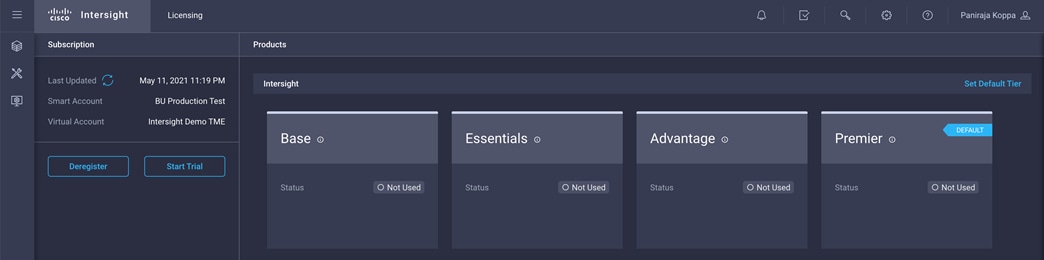
The Cisco Intersight platform uses a subscription-based license with multiple tiers. You can purchase a subscription duration of one, three, or five years and choose the required Cisco UCS server volume tier for the selected subscription duration. Each Cisco endpoint automatically includes a Cisco Intersight Base license at no additional cost when you access the Cisco Intersight portal and claim a device. You can purchase any of the following higher-tier Cisco Intersight licenses using the Cisco ordering tool:
● Cisco Intersight Essentials: Essentials includes all the functions of the Base license plus additional features, including Cisco UCS Central Software and Cisco Integrated Management Controller (IMC) supervisor entitlement, policy-based configuration with server profiles, firmware management, and evaluation of compatibility with the Cisco Hardware Compatibility List (HCL).
● Cisco Intersight Advantage: Advantage offers all the features and functions of the Base and Essentials tiers. It includes storage widgets and cross-domain inventory correlation across computing, storage, and virtual environments (VMware ESXi). It also includes OS installation for supported Cisco UCS platforms.
● Cisco Intersight Premier: In addition to the functions provided in the Advantage tier, Premier includes full subscription entitlement for Cisco Intersight Orchestrator, providing orchestration across Cisco UCS and third-party systems.
Servers in the Cisco Intersight managed mode require at least the Essentials license. The validation process for this document used a Premier license; however, all the functions covered in this document are supported with the Essentials license. For more information about the features provided in the various licensing tiers, see https://intersight.com/help/getting_started#licensing_requirements.
View the current Cisco Intersight Infrastructure Service licensing.
FlexPod setup for Cisco Intersight managed mode configuration
Figure 3 shows the connectivity between the various elements in this setup.
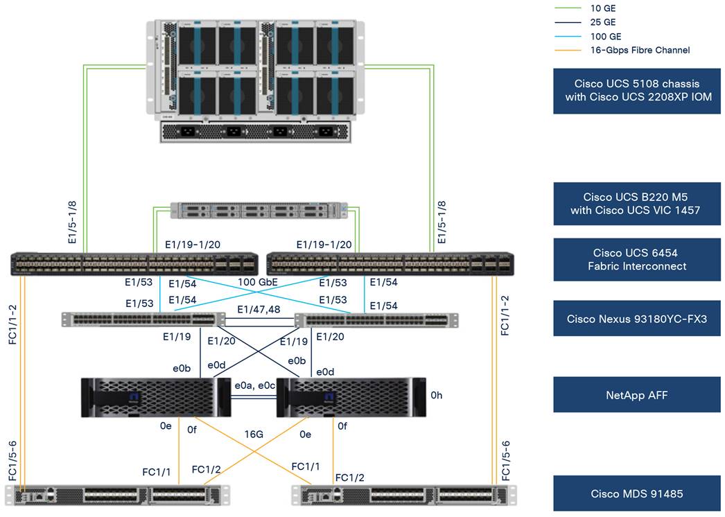
Topology to verify Cisco Intersight managed mode configuration in a FlexPod environment
To validate the Cisco Intersight managed mode configuration in a FlexPod environment, the components were set up as follows:
● Cisco UCS 6454 Fabric Interconnects provide the chassis and network connectivity.
● The Cisco UCS 5108 Blade Server Chassis connects to fabric interconnects using Cisco UCS 2208XP IOMs, where four 10 Gigabit Ethernet ports were used on each IOM to connect to the fabric interconnect.
● Cisco UCS B200 M5 servers contain fourth-generation Cisco virtual interface cards (VICs): UCSB-MLOM-40G-04.
● Cisco Nexus 9336C Switches running in Cisco NX-OS mode provide the switching fabric.
● Cisco UCS 6454 Fabric Interconnect 100 Gigabit Ethernet uplink ports connect to Cisco Nexus 9336C Switches in a virtual port channel (vPC).
● Cisco UCS 6454 Fabric Interconnects are connected to the Cisco MDS 9132T switches using 16-Gbps Fibre Channel connections configured as a port channel for SAN connectivity.
● The NetApp AFF controller connects to the Cisco Nexus 9336C Switches using 10 Gigabit Ethernet ports configured as a vPC.
● The NetApp AFF controller connects to the Cisco MDS 9132T switches using 16-Gbps Fibre Channel connections for SAN connectivity.
● The RHEL 8.3 operating system is installed on Cisco UCS B200 M5 servers to validate the infrastructure.
Configuration constructs for Cisco Intersight managed mode
Cisco Intersight managed mode unites the capabilities of the Cisco UCS platform and the cloud-based flexibility of the Cisco Intersight platform, thus unifying the management experience for standalone and fabric interconnect–attached systems. Cisco Intersight managed mode standardizes policy and operation management for fourth-generation fabric interconnects and Cisco UCS M5 servers.
At a high level, configuring Cisco UCS using Cisco Intersight managed mode consists of the steps shown in Figure 4. The details of these steps are presented in the following sections.
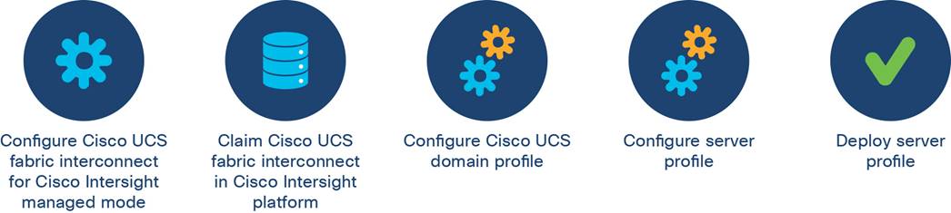
Steps for configuring Cisco UCS using Cisco Intersight managed mode
Setting up Cisco UCS fabric interconnects for Cisco Intersight managed mode
The initial configuration for a fabric interconnect can be performed using the serial console when the fabric interconnect boots for the first time. This can happen either during factory installation or after the existing configuration has been erased. During the initial configuration, for the management mode the configuration wizard enables customers to choose whether they want to manage the fabric interconnect through Cisco UCS Manager or the Cisco Intersight platform. Customers can switch the management mode for the fabric interconnects between Cisco Intersight and Cisco UCS Manager at any time. However, this is a disruptive process because it causes all endpoint configurations to be reset and results in the loss of the current configuration. In the validation process described here, the existing configuration on the Cisco UCS fabric interconnects was cleared, and the system was set up for Cisco Intersight managed mode.
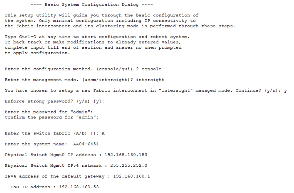
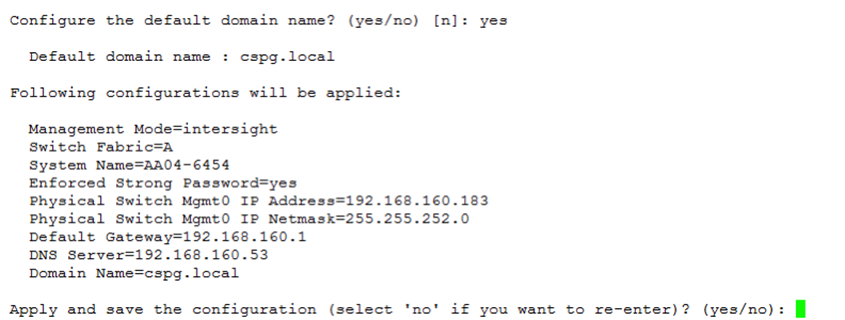
Figure 5 shows the output from the fabric interconnect console to enable Cisco Intersight managed mode.
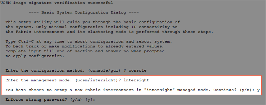
Fabric interconnects set up for Cisco Intersight managed mode
Claiming a Cisco UCS fabric interconnect in the Cisco Intersight platform
After you set up the Cisco UCS fabric interconnect for Cisco Intersight managed mode, you can add the fabric interconnects to a new or an existing Cisco Intersight account (Figure 6). The details of the device claim process are covered in the appendix. When a Cisco UCS fabric interconnect is successfully added to the Cisco Intersight platform, all future configuration steps are completed in the Cisco Intersight portal.
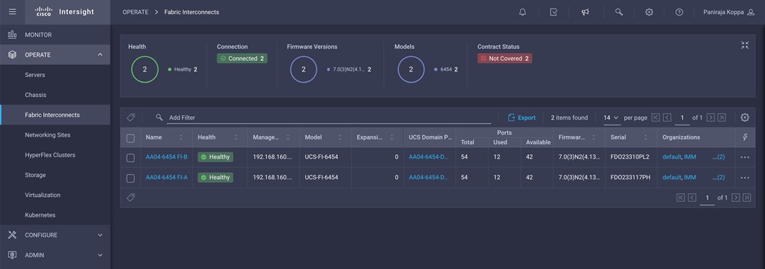
Cisco Intersight platform: Adding fabric interconnects
You can verify whether a Cisco UCS fabric interconnect is in Cisco UCS Manager managed mode or Cisco Intersight managed mode by clicking the fabric interconnect name and looking at the detailed information screen for the fabric interconnect, as shown in Figure 7.
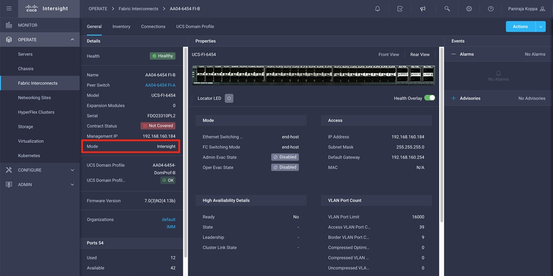
Fabric Interconnect in Cisco Intersight managed mode
Configuring a Cisco UCS domain profile
A Cisco UCS domain profile configures a fabric interconnect pair through reusable policies, allows configuration of the ports and port channels, and configures the VLANs and VSANs to be used in the network. It defines the characteristics of and configures the ports on the fabric interconnects. The domain-related policies can be attached to the profile either at the time of creation or later. One Cisco UCS domain profile can be assigned to one fabric interconnect domain, and the Cisco Intersight platform supports the attachment of one port policy per Cisco UCS domain profile. Policies that are attached to a Cisco UCS domain profile can be created either before or during the creation of the profile.
Some of the characteristics of the Cisco UCS domain profile set up for this validation are as follows:
● A single domain profile is created for the pair of Cisco UCS fabric interconnects.
● Separate port policies are defined for the two fabric interconnects because each fabric interconnect uses unique Fibre Channel and VSAN configurations. If boot from SAN were not required, the same port policy could have been reused across the two fabric interconnects.
● The VLAN configuration policy is common to the fabric interconnect pair because both fabric interconnects are configured for same set of VLANs. You can also keep iSCSI VSANs unique to each fabric interconnect. In such a case, separate VLAN policies would be required.
● The VSAN configuration policies are unique for the two fabric interconnects because the VSANs are unique.
● The Network Time Protocol (NTP), network connectivity, and system quality-of-service (QoS) policies are common to the fabric interconnect pair.
After the Cisco UCS domain profile has been successfully created, the fabric interconnects in FlexPod environment can do the following:
● Form an Ethernet port channel with the Cisco Nexus switch.
● Form a Fibre Channel port channel with the Cisco MDS switch.
● Discover the Cisco UCS chassis and the blades.
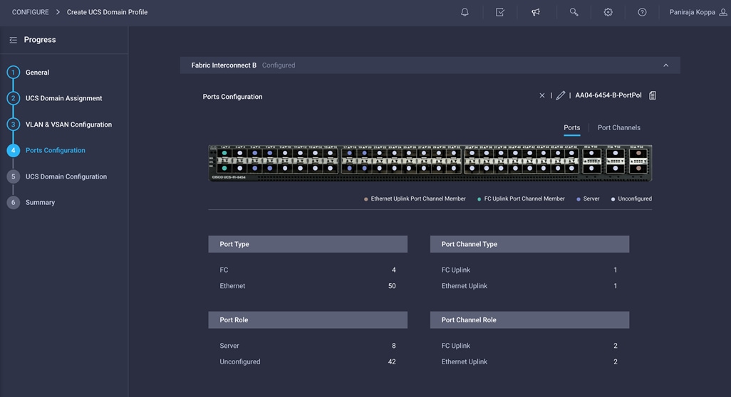
Figure 8 shows a summary of the Cisco UCS fabric interconnect and the port configuration after the Cisco UCS domain profile was deployed.
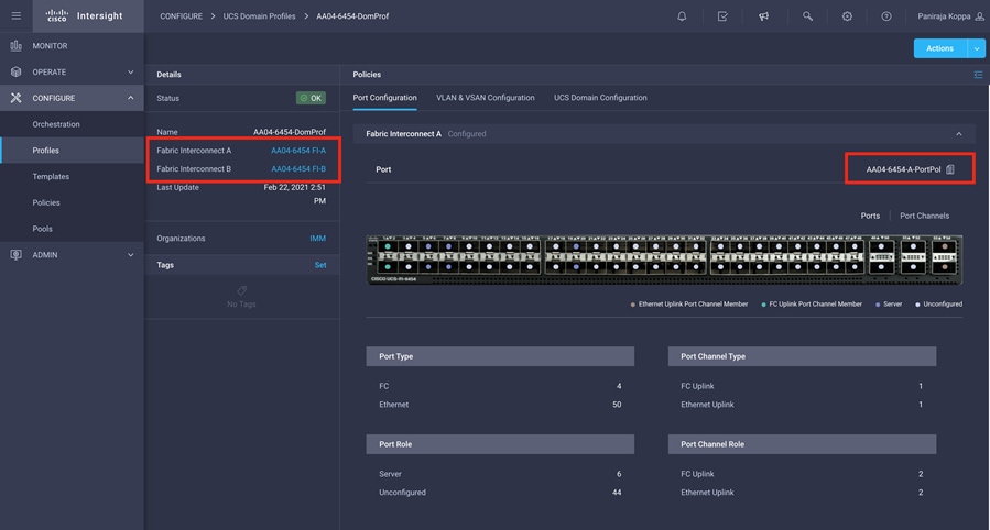
Cisco UCS domain profile
Creating and deploying a server profile
A server profile enables resource management by simplifying policy alignment and server configuration. You can create server profiles using the server profile wizard to provision servers, create policies to help ensure smooth deployment of servers, and eliminate failures caused by inconsistent configurations. The server profile wizard groups the server policies into the following four categories to provide a quick summary view of the policies that are attached to a profile:
● Compute policies: BIOS, boot order, and virtual media policies
● Management policies: Device connector; Intelligent Platform Management Interface (IPMI) over LAN; Lightweight Directory Access Protocol (LDAP); local user; network connectivity; Simple Mail Transfer Protocol (SMTP); Simple Network Management Protocol (SNMP); Secure Shell (SSH); Serial over LAN (SOL); syslog; and virtual keyboard, video, and mouse (KVM) policies
● Storage policies: Secure Digital (SD) card and storage policies (not used in this document)
● Network policies: LAN connectivity and SAN connectivity policies
◦ The LAN connectivity policy requires you to create Ethernet network policy, Ethernet adapter policy, and Ethernet QoS policy.
◦ The SAN connectivity policy requires you to create Fibre Channel network policy, Fibre Channel adapter policy, and Fibre Channel QoS policy.
The server profile enables resource management by simplifying policy alignment and server configuration. The server profile groups the server policies. Some of the policies used to create the server profile for this validation are as follows:
● BIOS policy is created to specify various server parameters in accordance with FlexPod best practices.
● Boot-order policy defines the following:
◦ Virtual media (KVM mapper DVD)
◦ Two vNICs to provide iSCSI LUN for boot from SAN linked to four SAN paths for NetApp iSCSI interfaces.
OR
Two vHBAs to provide FC LUN for boot from SAN linked to four SAN paths for NetApp Fibre Channel interfaces
● IMC access policy defines the management IP address pool for KVM access.
● Local user policy is used to create KVM access.
● LAN connectivity policy for iSCSI boot from SAN will use three vNICs: one for management and two overlay vNICs for iSCSI to provide multipathing and high availability.
OR
LAN connectivity policy for Fibre Channel boot from SAN will use single vNICs for management
● SAN connectivity policy is used to create two vHBAs—one for SAN A and one for SAN B—along with various policies and pools.
Figure 9 shows various policies associated with the server profile, and Figure 10 shows a successfully deployed server profile and associated blade.
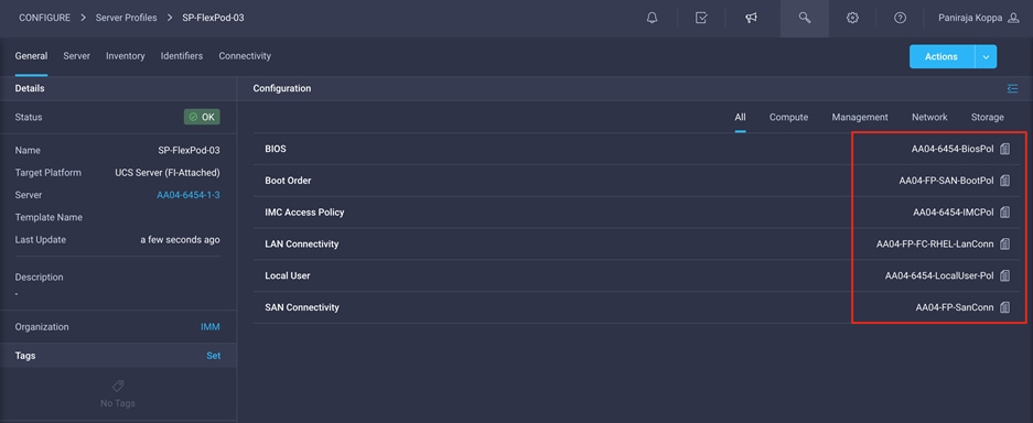
Server profile policies
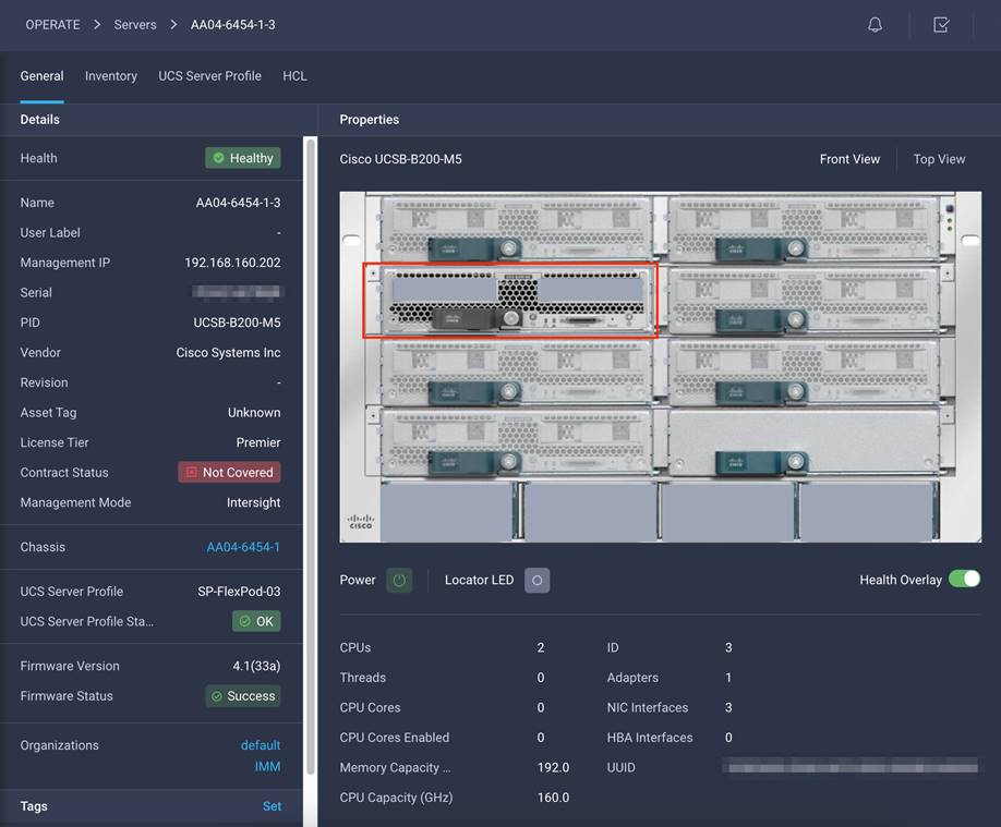
Server profile details
After a server profile has been successfully deployed, the server successfully boots from SAN storage hosted on the NetApp storage. Additional server profiles are created simply by cloning the first server profile and programming the Cisco MDS switches and NetApp controllers for various SAN parameters. For step-by-step deployment guidance for Cisco UCS and Cisco Intersight managed mode, refer to the appendix.
Automated provisioning using Terraform infrastructure as code
Terraform is an open-source infrastructure as code software tool that enables you to safely and predictably create, change, and improve infrastructure.
Terraform helps with
· Increased agility with reduced time to provision from weeks to minutes with automated workflow
· Control costs systematically as users and applications scale
· Reduce risk and discover errors before they happen with code reviews and embed provisioning guardrails
Terraform Providers
Providers are plugins that implement resource types likes Intersight.
Terraform CLI finds and installs providers when initializing a working directory. It can automatically download providers from a Terraform registry or load them from a local mirror or cache.
Why Terraform provider for the Cisco Intersight?
The Cisco Intersight platform supports the Terraform provider. The Terraform provider allows organizations to develop Cisco Intersight resources as self-service infrastructure using code rather than manual provisioning.
This approach provides several benefits:
· You can more quickly and easily scale Cisco Intersight resources. You can provision infrastructure in minutes, with little effort, using the automated workflows, performing the same tasks that used to take days.
· The operating model of Terraform is well suited for the Cisco Intersight platform, because it accommodates the shift from static to dynamic infrastructure provisioning. For example, if a resource is deleted in the Terraform configuration, it will be reflected in the Cisco Intersight platform when the new configuration is applied.
· Terraform maintains a state file, which is a record of the currently provisioned resources. State files provide a version history of Cisco Intersight resources, enabling a detailed audit trail of changes.
· The provider enables idempotency, producing the same result and state with repeated API calls.
The set of files used to describe infrastructure in Terraform is known as a Terraform configuration. The configuration is written using HashiCorp Configuration Language (HCL), a simple human-readable configuration language, to define a desired topology of infrastructure resources.
Automated Solution Deployment
The Terraform provider for Intersight offers an excellent way to easily build, scale, and manage the lifecycle of the FlexPod Datacenter. We can use it to automate entire infrastructure provisioning and for day-2 operations.
GitHub link below provides details of how to automate infrastructure provisioning detailed in this document. It has detailed steps and Terraform configurations for deploying the Cisco UCS with SAN boot (iSCSI and Fibre Channel) in a FlexPod Datacenter environment.
Link: https://github.com/ucs-compute-solutions/ConvergedInfrastructure_IMM_Terraform
REDAME file of the GitHub repository details the steps to automate the infrastructure provision for FlexPod using Terraform.
The Cisco Intersight platform is a SaaS infrastructure lifecycle management solution that delivers simplified configuration, deployment, maintenance, and support. The FlexPod solution delivers an integrated architecture that incorporates computing, storage, and network design best practices to reduce IT risk by validating the integrated architecture and helping ensure compatibility among the components.
Integrating the Cisco Intersight platform into a FlexPod environment provides global visibility of infrastructure health and status along with advanced management and support capabilities. The Cisco Intersight platform delivers a convenient SaaS solution with the capability to connect from anywhere and manage infrastructure through a browser or mobile app while allowing customers to stay ahead of problems and accelerate trouble resolution through advanced support capabilities.
Consult the following references for additional information about the topics discussed in this document.
Automated Provisioning using Terraform
https://github.com/ucs-compute-solutions/ConvergedInfrastructure_IMM_Terraform
Products and solutions
● Cisco Intersight platform:
https://www.intersight.com
● Cisco Intersight managed mode configuration guide: https://www.cisco.com/c/en/us/td/docs/unified_computing/Intersight/b_Intersight_Managed_Mode_Configuration_Guide.html
● Cisco Unified Computing System: http://www.cisco.com/en/US/products/ps10265/index.html
● Cisco UCS 6454 Fabric Interconnect: https://www.cisco.com/c/en/us/products/collateral/servers-unified-computing/datasheet-c78-741116.html
● Cisco UCS 5100 Series Blade Server Chassis: http://www.cisco.com/en/US/products/ps10279/index.html
● Cisco UCS B-Series Blade Servers: http://www.cisco.com/en/US/partner/products/ps10280/index.html
● Cisco UCS adapters: http://www.cisco.com/en/US/products/ps10277/prod_module_series_home.html
● Cisco Nexus 9000 Series Switches: http://www.cisco.com/c/en/us/products/switches/nexus-9000-series-switches/index.html
● NetApp ONTAP 9: http://www.netapp.com/us/products/platform-os/ontap/index.aspx
● Cisco UCS Hardware Compatibility Matrix: https://ucshcltool.cloudapps.cisco.com/public/
● NetApp Interoperability Matrix Tool: http://support.netapp.com/matrix/
● FlexPod Datacenter Design Guide: https://www.cisco.com/c/en/us/td/docs/unified_computing/ucs/UCS_CVDs/fp_dc_ontap_97_ucs_4_vmw_vs_67_U3_design.html
● FlexPod Datacenter Deployment Guide: https://www.cisco.com/c/en/us/td/docs/unified_computing/ucs/UCS_CVDs/fp_dc_ontap_97_ucs_4_vmw_vs_67_U3.html
Appendix: Configuration details
This appendix describes how to set up a Cisco UCS fabric in Cisco Intersight managed mode and specify the FlexPod-related computing configuration using the Cisco Intersight platform. This appendix does not discuss how to set up the switching infrastructure or the storage. Refer to the relevant FlexPod deployments guides for details about these components: https://www.cisco.com/c/en/us/td/docs/unified_computing/ucs/UCS_CVDs/fp_dc_ontap_97_ucs_4_vmw_vs_67_U3.html.
Set up Cisco Intersight managed mode on Cisco UCS fabric interconnects
The Cisco UCS fabric interconnects need to be set up to support Cisco Intersight managed mode. If you are converting an existing pair of Cisco UCS fabric interconnects, first erase the configuration and reboot your system. Converting fabric interconnects to Cisco Intersight managed mode is a disruptive process, and configuration information will be lost. Customers are encouraged to make a backup of their existing configuration if they plan only to test Cisco Intersight managed mode and then revert to Cisco UCS Manager managed mode.
1. Erase the configuration on existing fabric interconnects. Connect to each of the fabric interconnect consoles, log in as admin, and enter the following commands:
Note: This erasure process is not needed on brand-new fabric interconnects that have not been configured yet.
UCS-A# connect local-mgmt
UCS-A(local-mgmt)# erase configuration
All UCS configurations will be erased and system will reboot. Are you sure? (yes/no): yes
2. Configure Fabric Interconnect A (FI-A). On the Basic System Configuration Dialog screen, set the management mode to Intersight. All the remaining settings are similar to those for the Cisco UCS Manager managed mode (UCSM-Managed). Note that there is not a virtual IP address setting anymore when Cisco Intersight managed mode is selected.
3. After applying the settings, make sure you can ping the fabric interconnect management IP address. When Fabric Interconnect A is correctly set up and is available, Fabric Interconnect B will automatically discover Fabric Interconnect A during its setup process as shown in the next step.
4. Configure Fabric Interconnect B (FI-B). For the configuration method, choose console. Fabric Interconnect B will detect the presence of Fabric Interconnect A and will prompt you to enter the admin password for Fabric Interconnect A. Provide the management IP address for Fabric Interconnect B and apply the configuration.
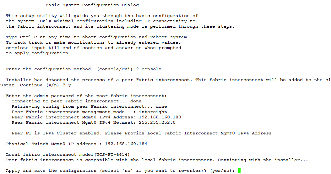
Set up a Cisco Intersight account
In this step, using the unique device information for the Cisco UCS, you set up a new Cisco Intersight account. Customers also can choose to add the Cisco UCS devices set up for Cisco Intersight managed mode to an existing Cisco Intersight account; however, that procedure is not covered in this document.
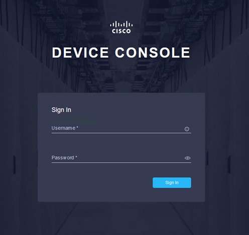
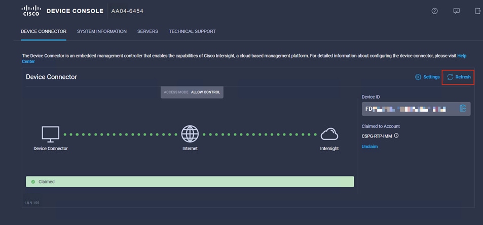
After completing the initial configuration for the fabric interconnects, log in to Fabric Interconnect A using your web browser to capture the Cisco Intersight connectivity information.
1. Use the management IP address of Fabric Interconnect A to access the device from a web browser and the previously configured admin password to log in to the device.
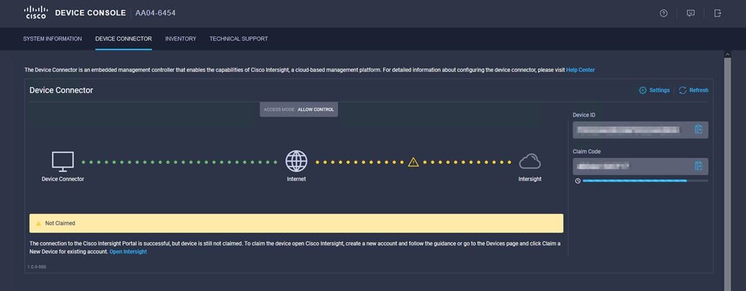
2. Under DEVICE CONNECTOR, you should see the current device status as ”Not claimed.” Note, or copy, the Device ID and Claim Code information to use to set up a new Cisco Intersight account.
Note: The Device ID and Claim Code information can also be used to claim the Cisco UCS devices set up with Cisco Intersight managed mode in an existing Cisco Intersight account.
Create a new Cisco Intersight account
Next, create a new Cisco Intersight account.
1. Visit https://www.intersight.com and click “Don't have an Intersight Account? Create an account.”
2. Provide an account name and the device information captured in the preceding steps to create the account. This step will automatically add the Cisco UCS device to the new Cisco Intersight account.

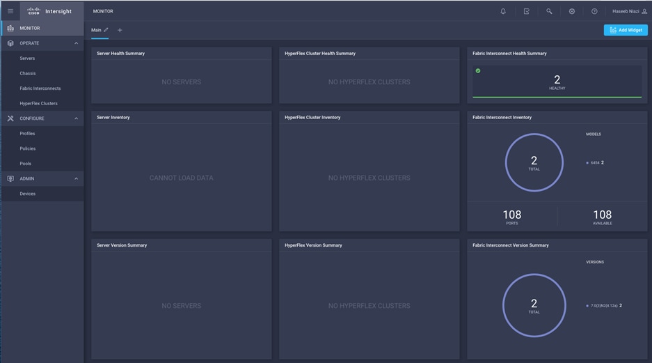
3. After the account has been created successfully, click Go To Intersight.

4. You should see a screen with your Cisco Intersight account.
Verify the addition of Cisco UCS fabric interconnects to Cisco Intersight
Now verify that Cisco UCS fabric interconnects are added to your account in Cisco Intersight.
1. Go back to the web GUI of the Cisco UCS fabric interconnect and click the Refresh button.
2. The fabric interconnect status should now be set to Claimed.
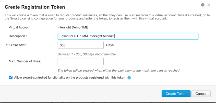
When setting up a new Cisco Intersight account (as discussed in this document), the account needs to be enabled for Cisco Smart Software Licensing.
1. Associate the Cisco Intersight account with Cisco Smart Licensing by following these steps:
◦ Log in to the Cisco Smart Licensing portal: https://software.cisco.com/software/csws/ws/platform/home?locale=en_US#module/SmartLicensing.
◦ Select the correct virtual account.
◦ Under Inventory > General, generate a new token for product registration.
◦ Copy this newly created token.
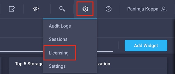
2. With the Cisco Intersight account associated with Cisco Smart Licensing, log in to the Cisco Intersight portal and click Settings (the gear icon) in the top-right corner. Choose Licensing.
3. Under Cisco Intersight > Licensing, click Register.
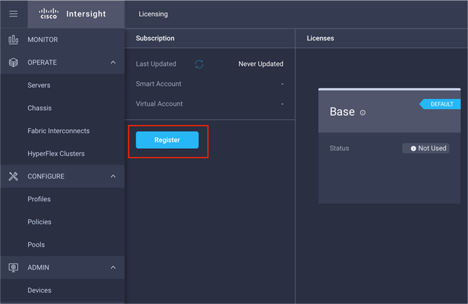
4. Enter the copied token from the Cisco Smart Licensing portal.
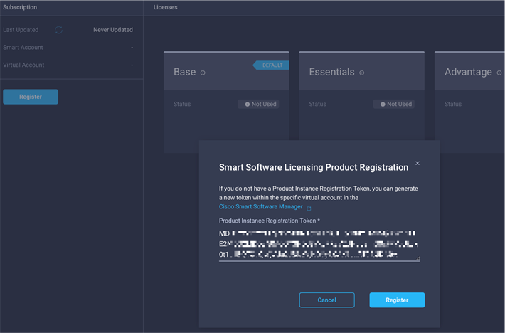
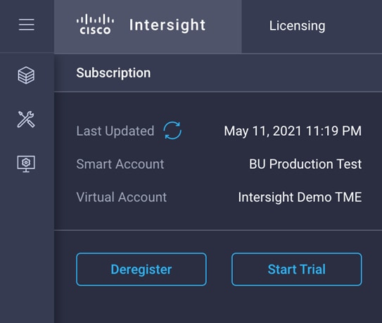
5. Click Register and wait for registration to go through. When the registration is successful, the information about the associated Cisco Smart account is displayed.
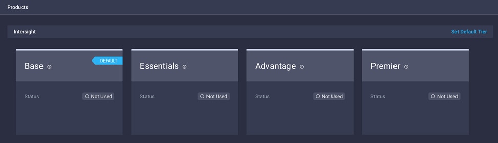
6. For all new accounts, the default licensing tier is set to Base. For Cisco Intersight managed mode, the default tier needs to be changed to Essential or a higher tier. To make this change, click Set Default Tier.
7. Select the tier supported by your Smart License.
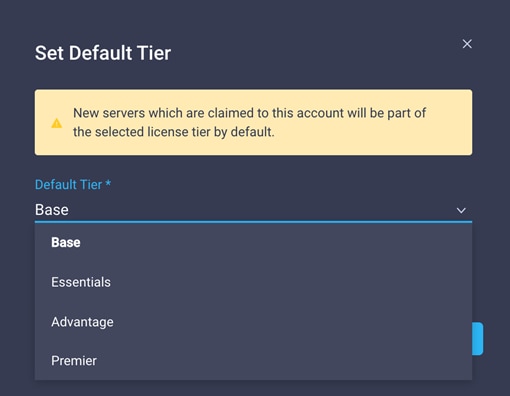
8. In this deployment, the default license tier is set to Premier.
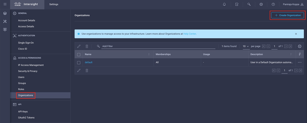
Set up Cisco Intersight organization
You need to define all Cisco Intersight managed mode configurations for Cisco UCS, including policies, under an organization. To define a new organization, follow these steps:
1. Log in to the Cisco Intersight portal.
2. Click Settings (the gear icon) and choose Settings.
3. Click Organizations in the middle panel.
4. Click Create Organization in the top-right corner.
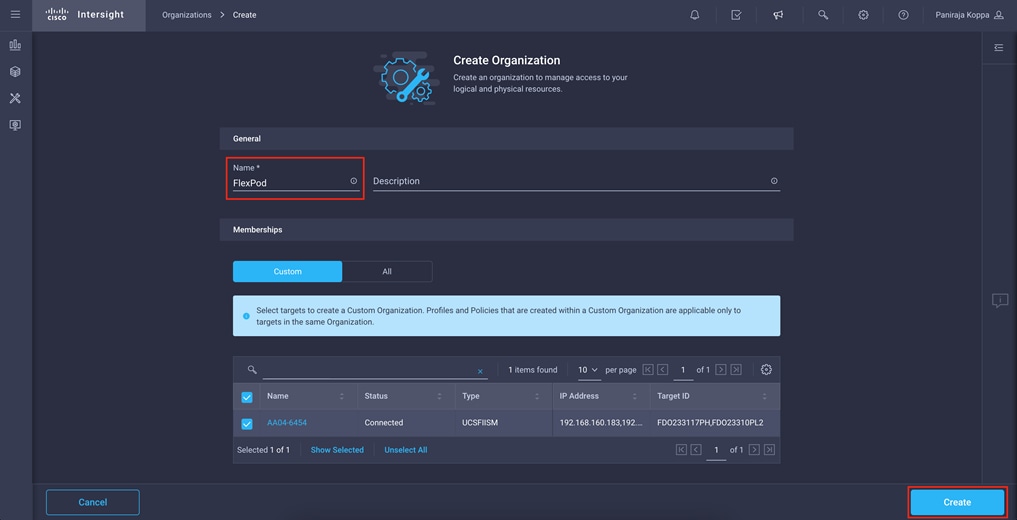
5. Provide a name for the organization (for example, FlexPod).
6. Under Memberships, select Custom.
7. Select the recently added Cisco UCS device for this organization.
8. Click Create.
Configure a Cisco UCS domain profile
A Cisco UCS domain profile configures a fabric interconnect pair through reusable policies, allows configuration of the ports and port channels, and configures the VLANs and VSANs in the network. It defines the characteristics of and configures ports on fabric interconnects. The domain-related policies can be attached to the profile either at the time of creation or later. One Cisco UCS domain profile can be assigned to one fabric interconnect domain.
To create a Cisco UCS domain profile, follow these steps:
1. Log in to the Cisco Intersight portal
2. Click to expand CONFIGURE in the left pane and select Profiles.
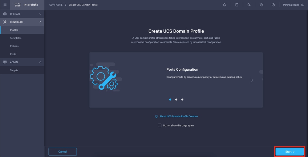
3. In the main window, select UCS Domain Profiles and click Create UCS Domain Profile.
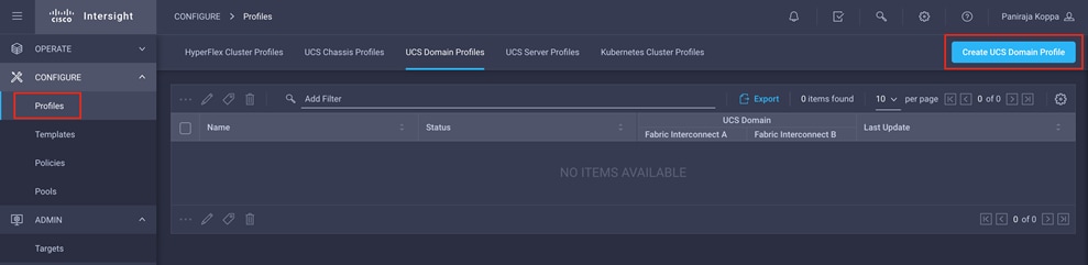
4. On the Create UCS Domain Profile screen, click Start.
Follow these steps for the general configuration:
1. Choose the organization from the drop-down menu (for example, FlexPod).
2. Provide a name for the domain profile (for example, AA04-6454-DomProf).
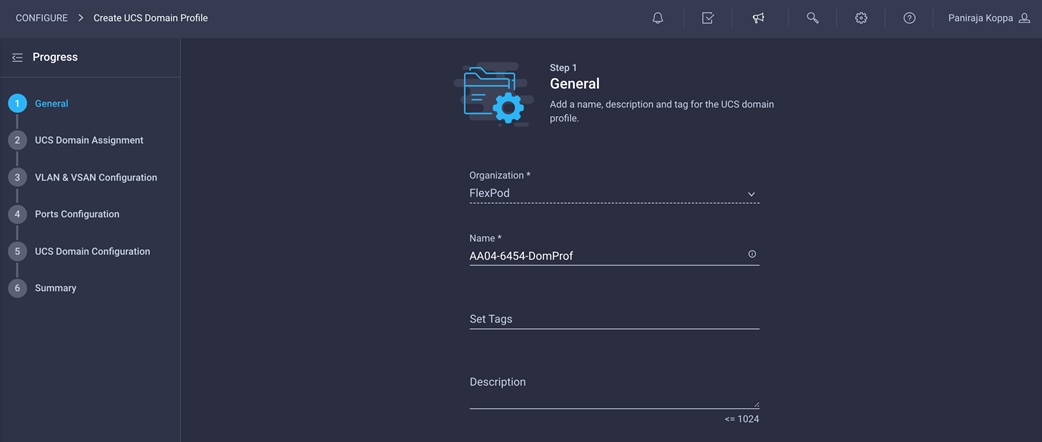
3. Click Next.
Step 2: UCS Domain Assignment
Follow these steps for Cisco UCS domain assignment:
1. Assign the Cisco UCS domain to this new domain profile by clicking Assign Now and selecting the previously added Cisco UCS domain (AA04-6454).
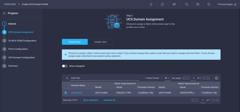
2. Click Next.
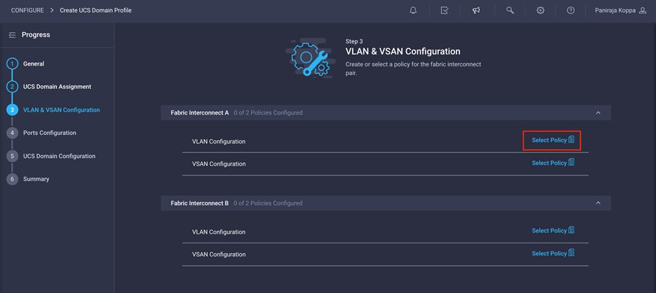
Step 3: VLAN and VSAN Configuration
In this step, you create a single VLAN policy for both fabric interconnects, but you create individual policies for the VSANs because the VSAN IDs are unique for each fabric interconnect. Separate VLAN policies can be created if you want to keep VLANs unique to each fabric interconnect.
Follow these steps to create and apply the VLAN policy:
1. Click Select Policy next to VLAN Configuration under Fabric Interconnect A. Then, in the pane on the right, click Create New.
2. Choose the organization from the drop-down menu (for example, FlexPod) and provide a name for the policy (for example, AA04-6454-VLANPol).
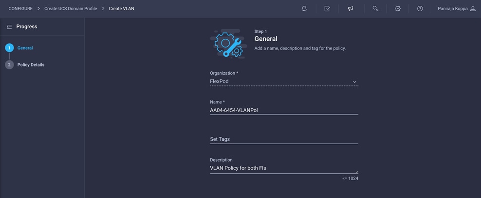
3. Click Next.
4. Click Add VLANs.
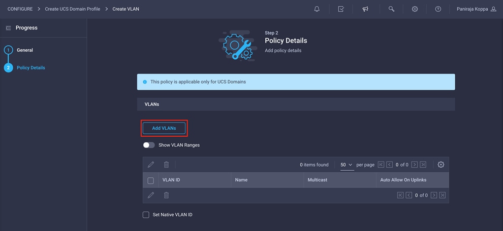
5. Provide a name and VLAN ID for the native VLAN (for example, Native-Vlan and 2).
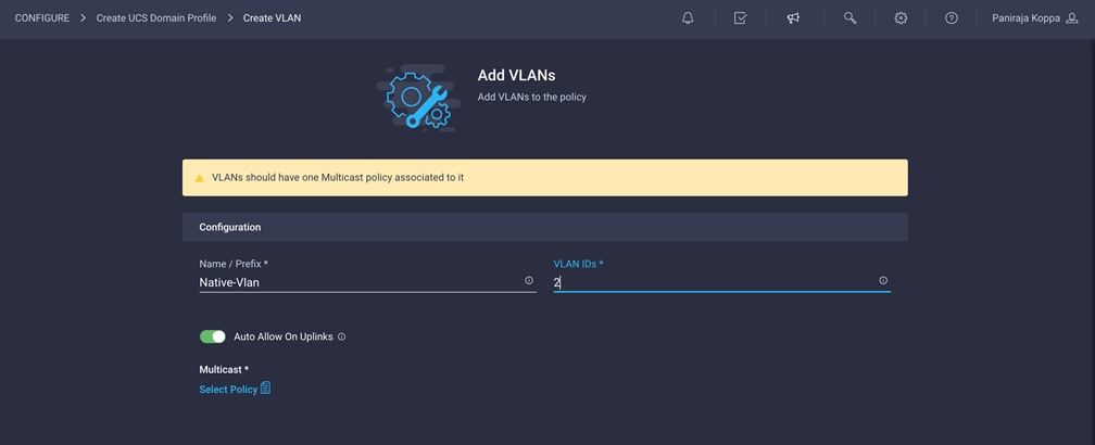
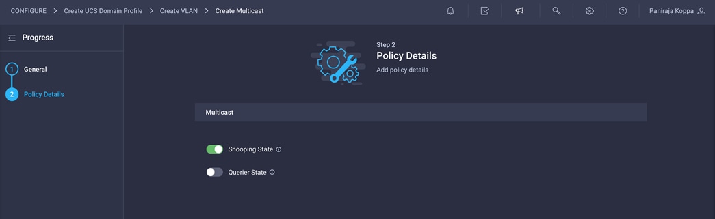
6. Click Select Policy for Multicast and then, in the pane on the right, click Create New.
7. Choose the organization from the drop-down menu (for example, FlexPod) and provide a name for the policy (for example, AA04-6454-MCastPol).
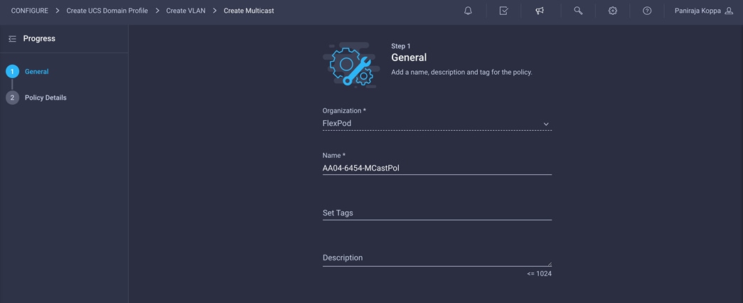
8. Keep the default setting of Snooping state enabled and Querier state disabled and click Create
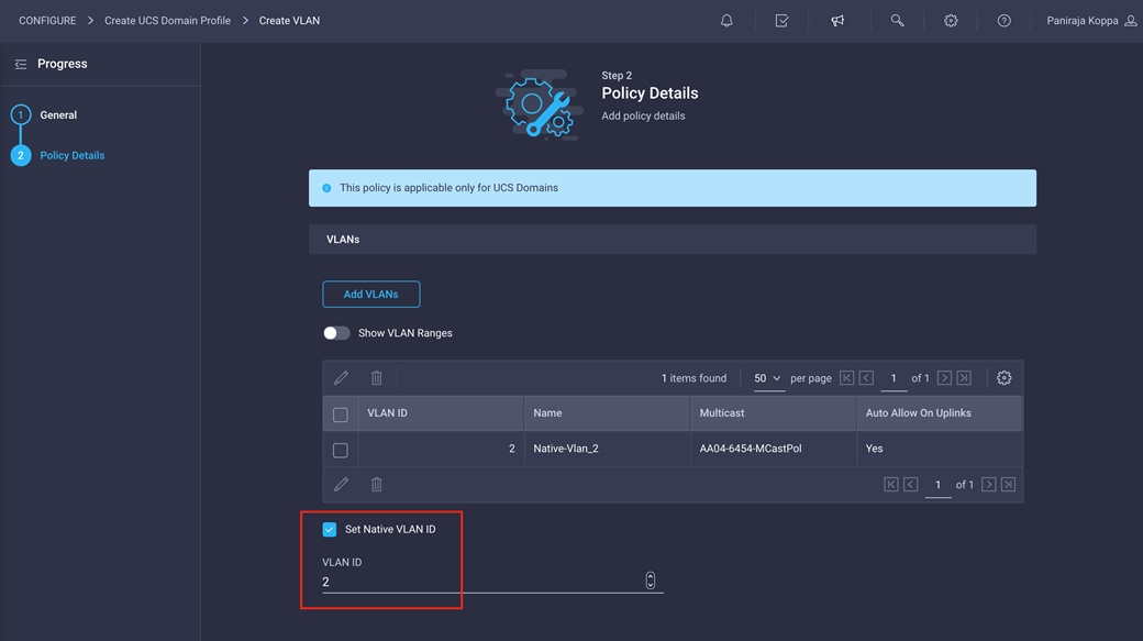
9. Click Add
10. Select Set Native VLAN ID and enter the VLAN number (for example, 2) under VLAN ID.
11. Add the remaining VLANs for FlexPod by clicking Add VLANs and entering the VLANs one by one. Select the same multicast policy for all the VLANs. The VLANs used for this validation are shown in the screen image here.
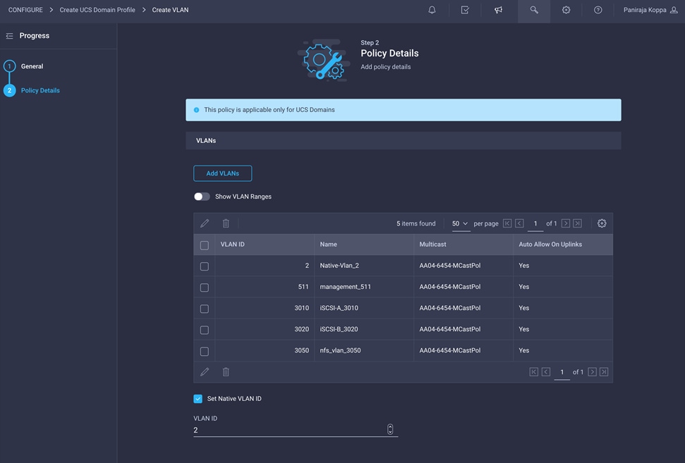
Note: The iSCSI VLANs shown in the screen image above are needed only if you are using iSCSI boot from SAN. Include the NFS VLAN if you are using an NFS datastore.
12. Click Create at the bottom right to create all the VLANs.
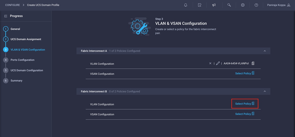
13. Click Select Policy next to VLAN Configuration for Fabric Interconnect B and select the same VLAN policy that was created in the preceding step.
Create and apply VSAN policy (Fibre Channel Only)
Follow these steps to create and apply the VSAN policy. These steps apply only for Fibre Channel SAN configuration.
1. Click Select Policy next to VSAN Configuration under Fabric Interconnect A. Then, in the pane on the right, click Create New.
2. Choose the organization from the drop-down menu (for example, FlexPod) and provide a name for the policy (for example, AA04-6454-A-VSANPol).
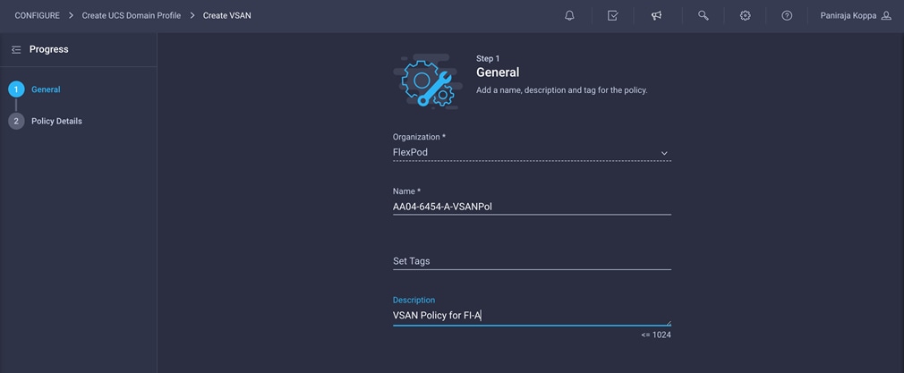
3. Click Next.
4. Click Add VSAN and provide a name (for example, VSAN-A), VSAN ID (for example, 111), and the associated Fibre Channel over Ethernet (FCoE) VLAN ID (for example, 111) for SAN A.
5. Click Add.
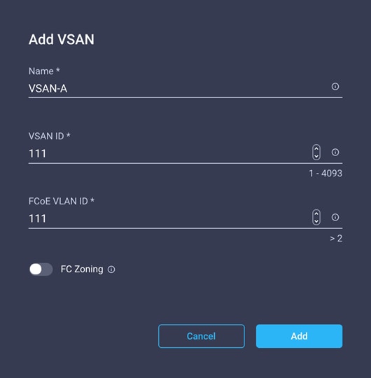
6. Enable uplink trunking for this VSAN.
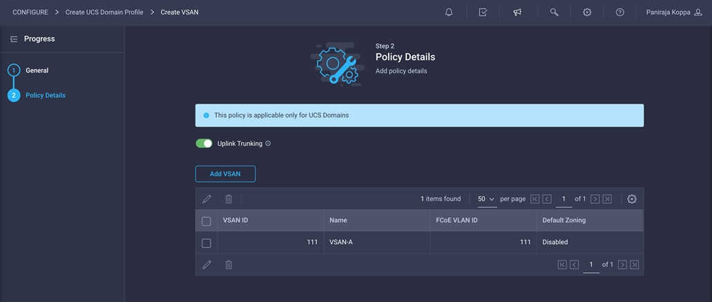
7. Click Create.
8. Repeat the same steps to create a new VSAN policy for SAN B. Click Select Policy next to VSAN Configuration under Fabric Interconnect B. Then, in the pane on the right, click Create New.
9. Choose the organization from the drop-down menu (for example, FlexPod) and provide a name for the policy (for example, AA04-6454-B-VSANPol).
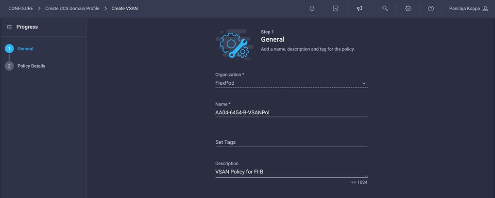
10. Click Next.
11. Click Add VSAN and provide a name (for example, VSAN-B), a VSAN ID (for example, 112), and the associated FCoE VLAN ID (for example, 112) for SAN-B.
12. Click Add.
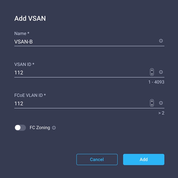
13. Enable uplink trunking for this VSAN.
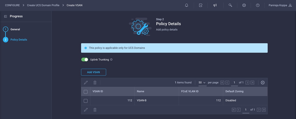
14. Click Create.
15. Verify that a common VLAN policy and two unique VSAN policies are associated with the two fabric interconnects.
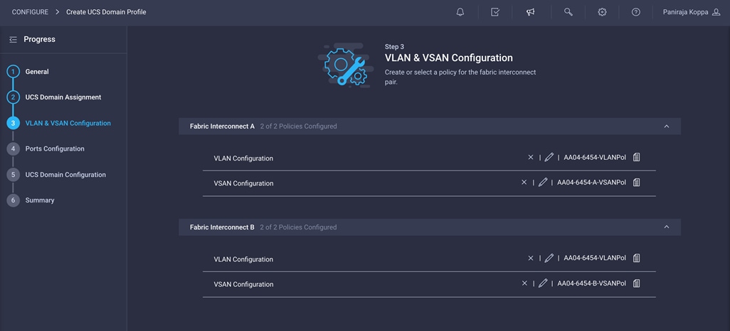
16. Click Next.
Follow these steps to configure the ports:
1. Click Select Policy for Fabric Interconnect A.
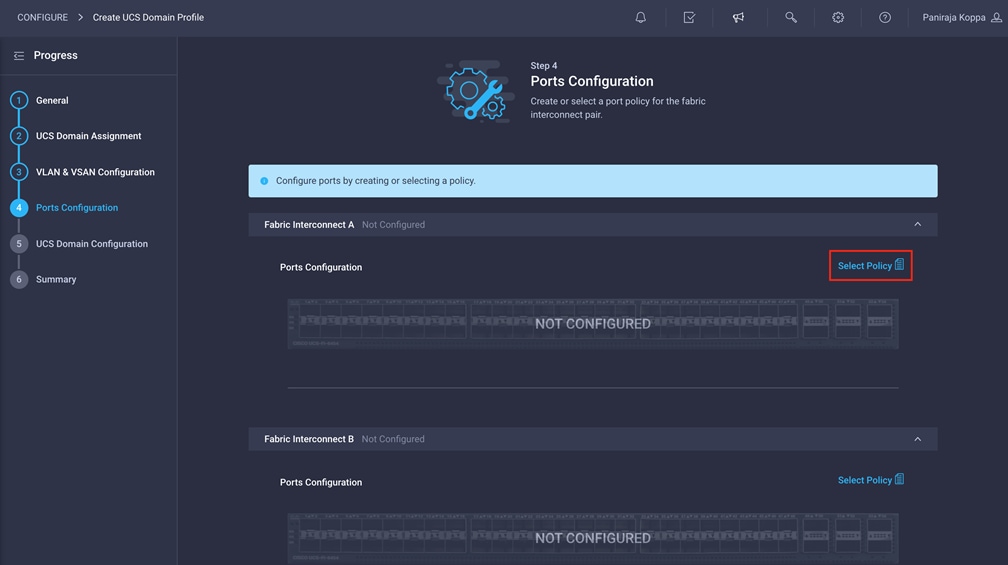
2. Click Create New in the top-right pane to define a new port configuration policy.
Note: This document uses separate port policies for the two fabric interconnects because each fabric interconnect uses unique Fibre Channel and VSAN information. If boot from SAN were not required, the same port policy could have been reused across the two fabric interconnects.
3. Choose the organization from the drop-down menu.
4. Provide a name for the policy (for example, AA04-6454-A-PortPol). Change the switch model if it is not 6454.
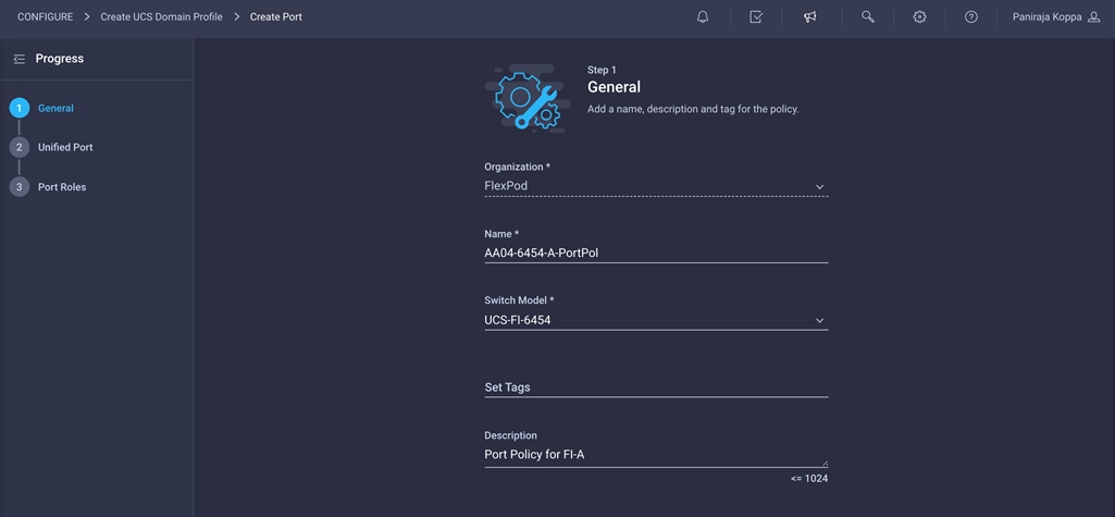
5. Move the slider to set up unified ports. In this example, the first four ports were selected as Fibre Channel ports. Click Next.
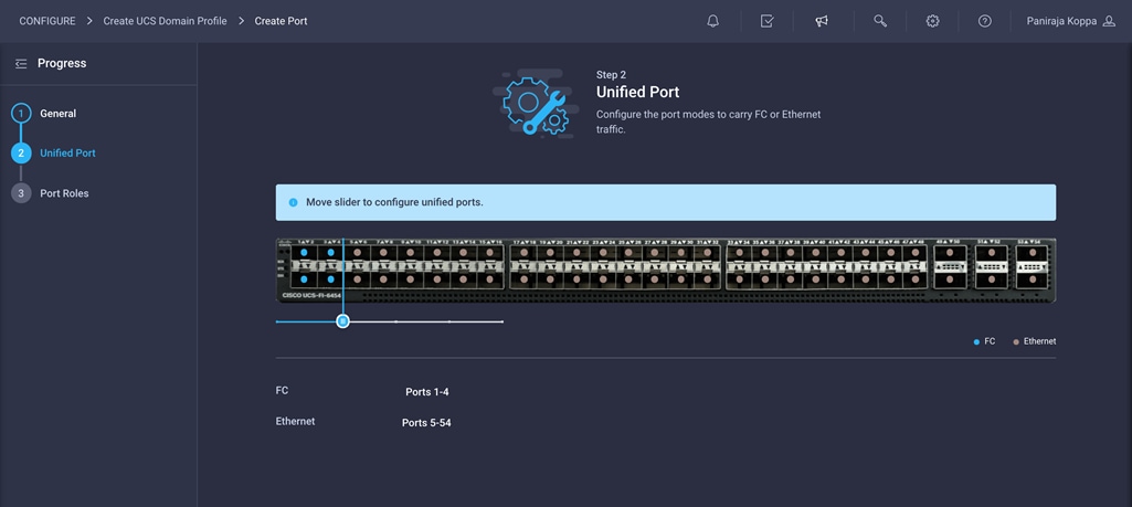
6. Verify that ports 1 to 4 are indeed configured as Fibre Channel ports.
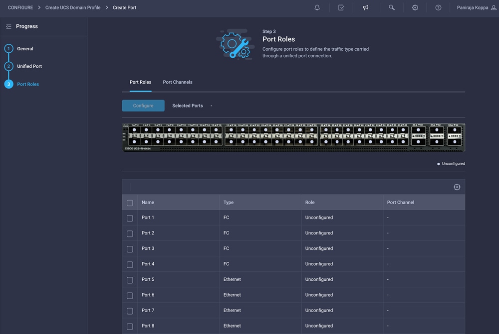
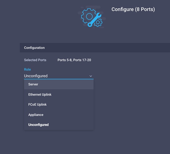
7. Select all the ports that need to be configured as server ports by clicking the ports in the graphics (or from the list below the graphic). When all ports are selected, click Configure.
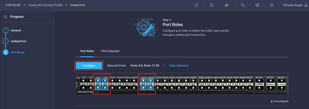
8. From the drop-down menu, choose Server as the role. Leave Forward Error Correction (FEC) set to Auto and click Save.
9. Configure the Ethernet uplink port channel by selecting the port channel in the main pane and then clicking Create Port Channel.
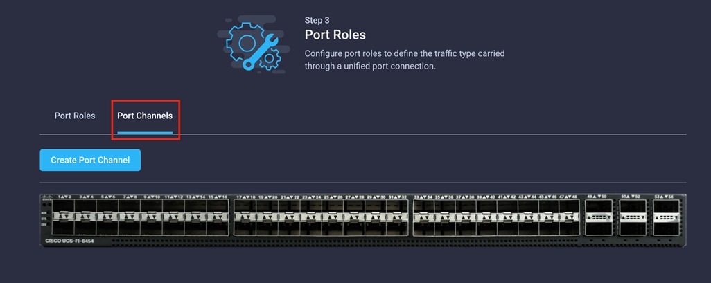
10. Choose Ethernet Uplink Port Channel as the role, provide a port-channel ID (for example, 15), and choose a value for Admin Speed (Auto is used in this example).
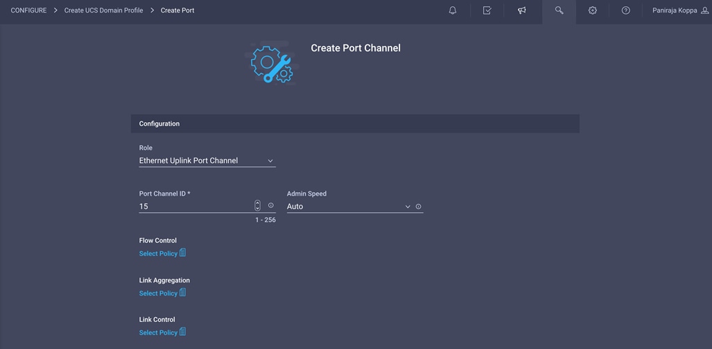
11. Click Save.
12. Configure a Fibre Channel Port Channel by selecting the port channel in the main pane again and clicking Create Port Channel.
13. In the drop-down menu under Role, choose FC Uplink Port Channel.
14. Provide a port-channel ID (for example, 111), choose a value for Admin Speed (16Gbps is used here), and provide a VSAN ID (for example, 111).
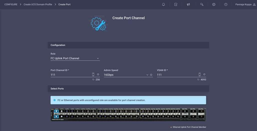
15. Click Save.
16. Verify the port-channel IDs and ports after both the Ethernet uplink port channel and the Fibre Channel uplink port channel have been created.
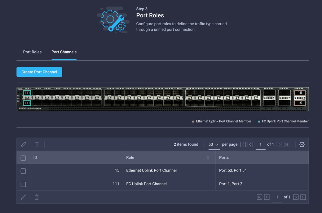
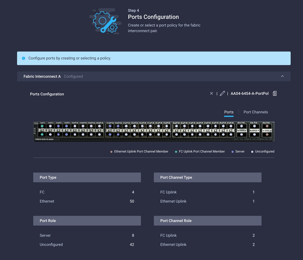
17. Click Save to create the port policy for Fabric Interconnect A. Use the summary screen here to verify that the ports were selected and configured correctly.
18. Now create policy for Fabric Interconnect B. Click Select Policy for Fabric Interconnect B, and in the pane at the right, click Create New.
19. Choose the organization from the drop-down menu (for example, FlexPod) and provide a name for the policy (for example, AA04-6454-B-PortPol).
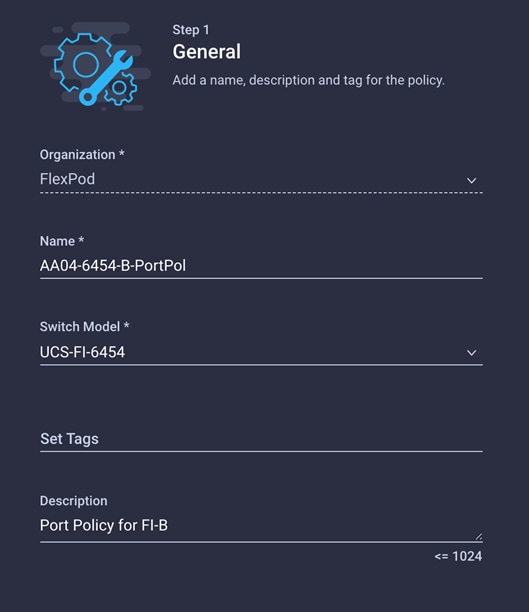
20. Repeat the steps you used for Fabric Interconnect A to configure Fibre Channel ports, server ports, and Ethernet and Fibre Channel port channels with appropriate IDs (for example, Ethernet port-channel ID 16 and Fibre Channel port-channel ID 112).
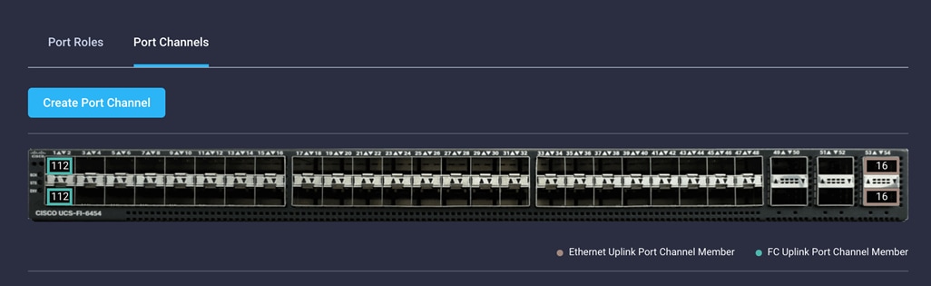
21. Use the summary screen shown here to verify that the ports were selected, port channels for Ethernet and FC are configured correctly for Fabric Interconnect B.
22. When the port configuration for both fabric interconnects is complete and looks good, click Next.
Step 5: UCS Domain Configuration
You need to define some additional policies, such as NTP, network connectivity, and system QoS, for the Cisco UCS domain configuration.
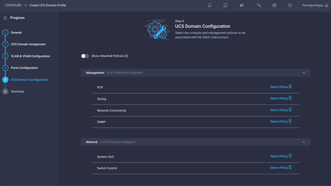
To define an NTP server for the Cisco UCS domain, configure NTP policy.
1. Click Select Policy next to NTP and then, in the pane on the right, click Create New.
2. Choose the organization from the drop-down menu (for example, FlexPod) and provide a name for the policy (for example, AA04-6454-NTPPol).
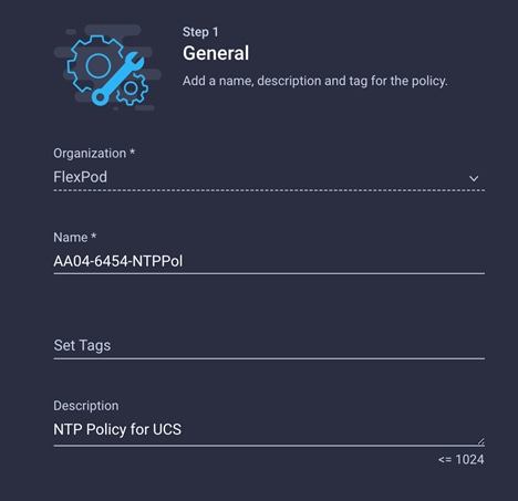
3. Click Next.
4. Enable NTP, provide the NTP server IP addresses (for example, 192.168.160.254), and select the time zone from the drop-down menu (for example, America/Los_Angeles).
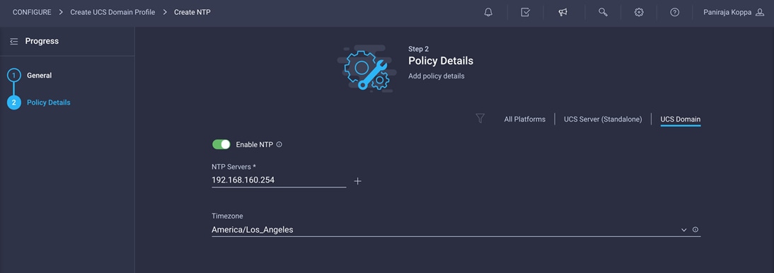
5. Click Create.
Configure network connectivity policy
To define the Doman Name Service (DNS) servers for Cisco UCS, configure network connectivity policy.
1. Click Select Policy next to Network Connectivity and then, in the pane on the right, click Create New.
2. Choose the organization from the drop-down menu (for example, FlexPod) and provide a name for the policy (for example, AA04-6454-NetConnPol).
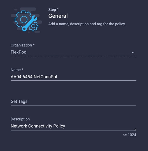
3. Provide DNS server IP addresses for Cisco UCS (for example, 192.168.160.53 and 192.168.160.54).
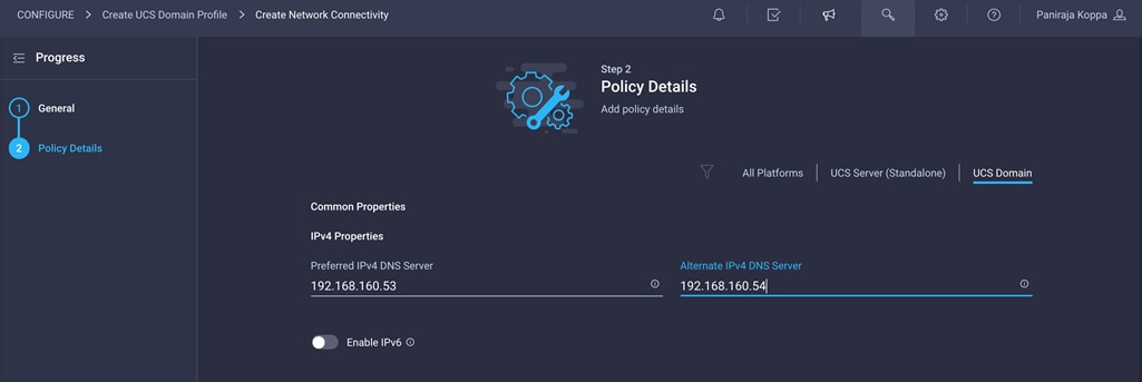
4. Click Create.
To define the QoS settings for Cisco UCS, configure system QoS policy.
1. Click Select Policy next to System QoS and then, in the pane on the right, click Create New.
2. Choose the organization from the drop-down menu (for example, FlexPod) and provide a name for the policy (for example, AA04-6454-SystemQoSPol).
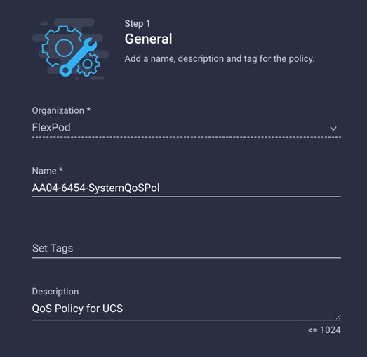
3. Keep the default selections or change the parameters if necessary. In this document, the MTU setting for Ethernet traffic is kept as 9216.
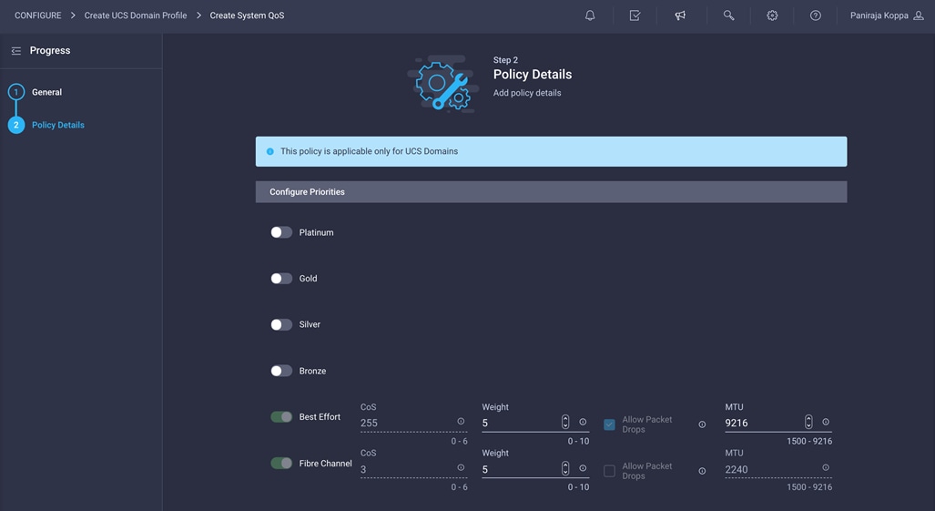
4. Click Create.
5. Click Next.
You can optionally configure syslog policy if you want to keep the logs in a syslog server. If you want a custom MAC address aging time or link control settings, you can create a switch control policy.
Verify all the settings (including the fabric interconnect settings, by expanding the settings) and make sure that the configuration is correct.
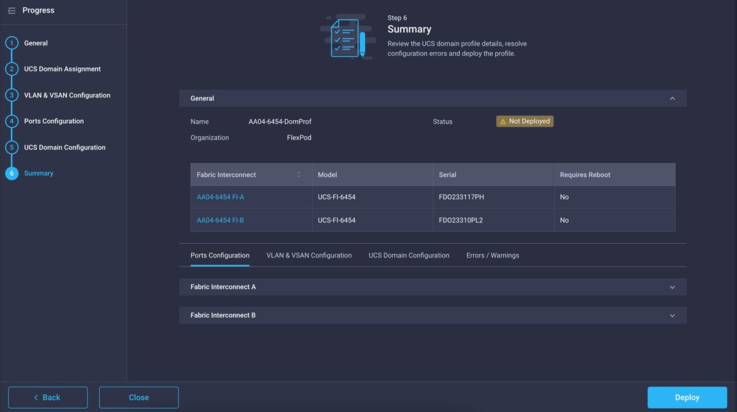
Deploy the Cisco UCS domain profile
After verifying the configuration, deploy the Cisco UCS profile.
1. Click Deploy.
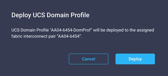
2. Acknowledge the warning and click Deploy again.
The system will take some time to validate and configure the settings on the fabric interconnects. You can log into the terminal or console servers to see when the Cisco UCS fabric interconnects have finished configuration and are successfully rebooted.
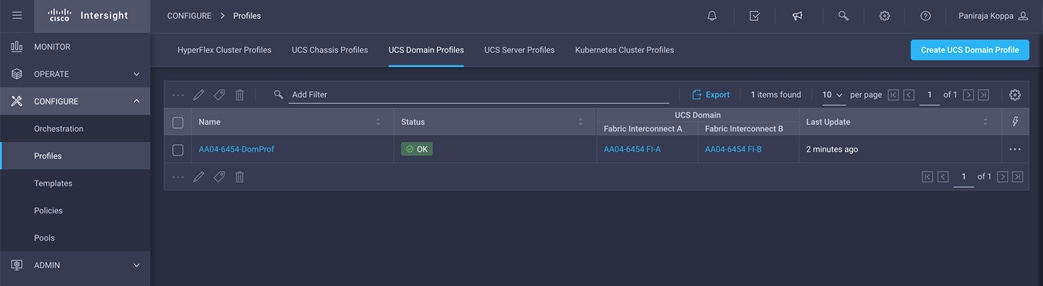
Verify Cisco UCS domain profile deployment
When the Cisco UCS domain profile has been successfully deployed, the Cisco UCS chassis and the blades should be successfully discovered.
1. Log in to the Cisco Intersight portal. Under CONFIGURE > Profiles > UCS Domain Profiles, verify that the domain profile has been successfully deployed.
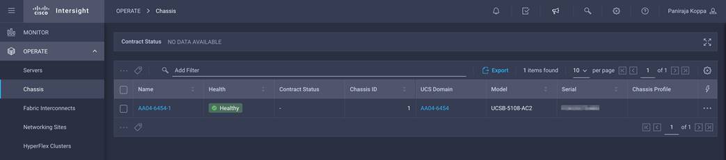
2. Verify that the chassis has been discovered and is visible under OPERATE > Chassis.
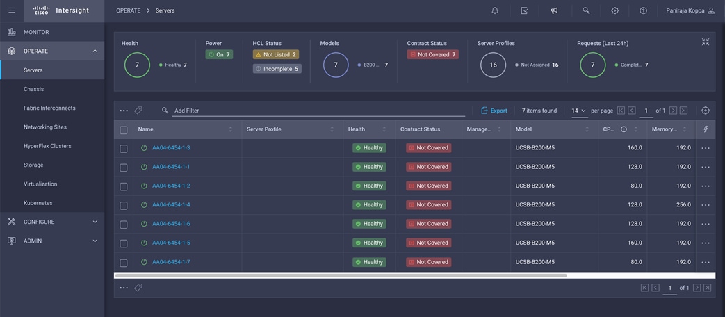
3. Verify that the servers have been successfully discovered and are visible under OPERATE > Servers.
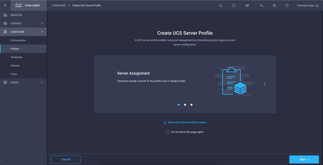
In the Cisco Intersight platform, a server profile enables resource management by simplifying policy alignment and server configuration. You can create server profiles using the server profile wizard to provision servers, create policies to help ensure smooth deployment of servers, and eliminate failures that are caused by inconsistent configuration. After creating server profiles, you can edit, clone, deploy, or unassign them as required.
To configure a server profile, follow these steps:
1. Log in to the Cisco Intersight portal.
2. Go to Configure > Profiles and in the main window select UCS Server Profile.
3. Click Create UCS Server Profile.
4. Click Start.
Follow these steps for the general configuration:
1. Choose the organization from the drop-down menu (for example, FlexPod) and provide a name for the server profile (for example, FlexPod-RHEL-Host-1).
2. Select UCS Server (FI-Attached).
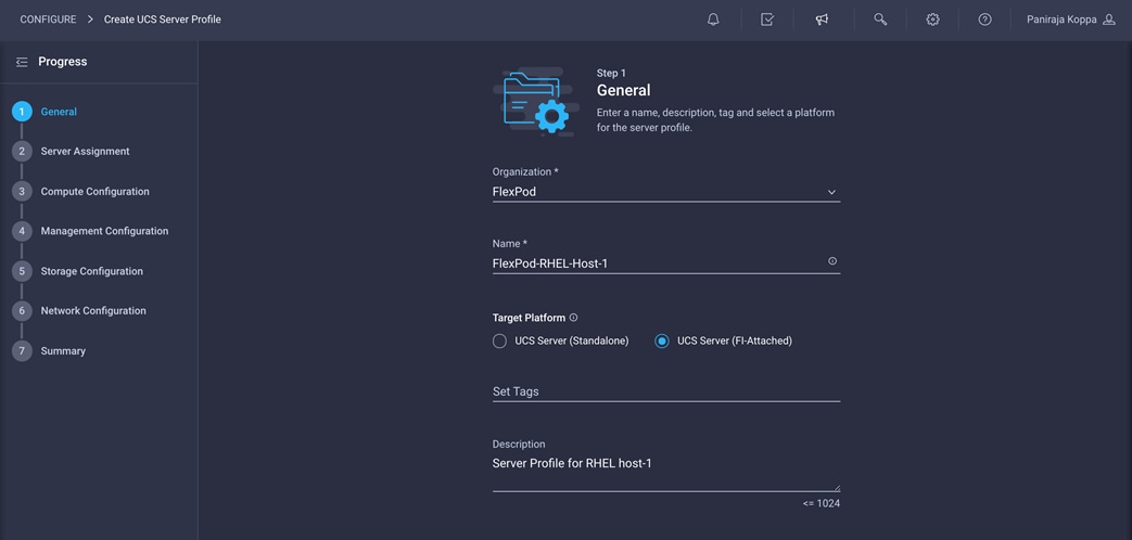
3. Click Next.
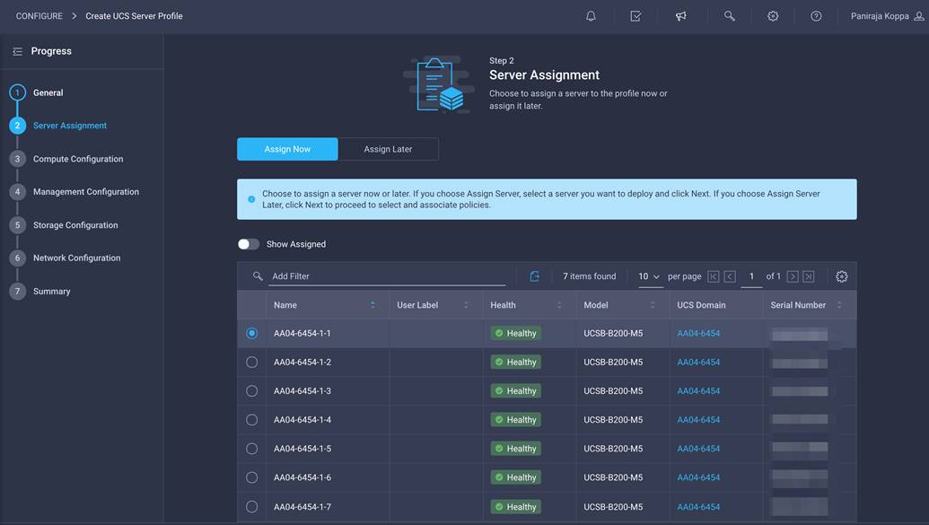
Follow these steps for server assignment:
1. Make sure server assignment is set to Assign Now.
2. Select a server (for example, AA06-6454-1-1) and click Next.
Next, configure the computing resources.
Follow these steps to configure BIOS policy:
1. Click Select Policy next to BIOS Configuration and the, in the pane on the right, click Create New.
2. Choose the organization from the drop-down menu (for example, FlexPod) and provide a name for the policy (for example, AA04-6454-BiosPol).
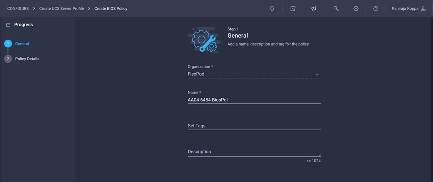
3. Click Next.
4. On the Policy Details screen, select appropriate values.
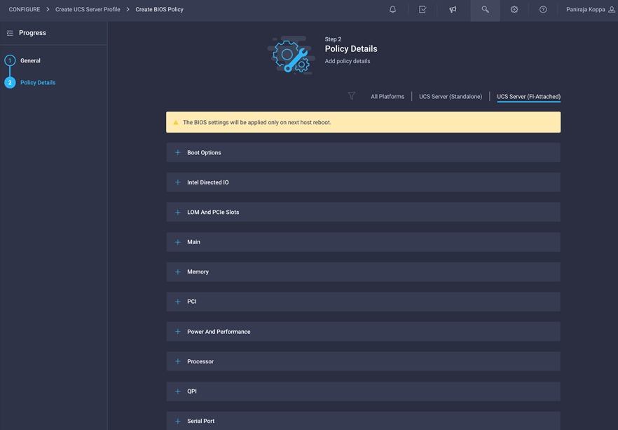
The validation described in this document used the following values to align with the Cisco Validated Designs for FlexPod:
◦ LOM and PCIe Slot > CDN Support for LOM: Enabled
◦ Processor > DRAM Clock Throttling: Performance
◦ Processor > Freq Floor Override: Enabled
◦ Processor > CPU C State: Disabled
◦ Processor > Processor C1E: Disabled
◦ Processor > Processor C3 Report: Disabled
◦ Processor > Processor C6 Report: Disabled
◦ Processor > Power Technology: Custom
◦ Processor > Energy Performance: Performance
◦ Memory > NVM Performance Setting: Balanced Profile
◦ Memory > Memory RAS Configuration: Maximum Performance
5. Click Create.
This solution is validated with both iSCSI and Fibre Channel boot-from-SAN configurations. Choose one policy based on your requirements.
Configuring boot-order policy for Fibre Channel
Follow these steps to configure boot-order policy for Fibre Channel:
1. Click Select Policy next to Boot Order Configuration and then, in the pane on the right, click Create New.
2. Choose the organization from the drop-down menu (for example, FlexPod) and provide a name for the policy (for example, AA04-6454-FC-BootPol).

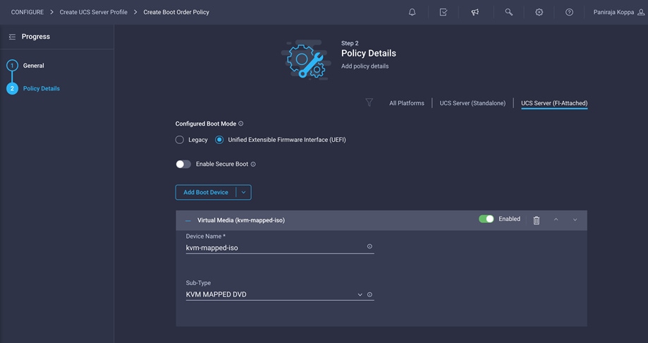
3. Click Next.
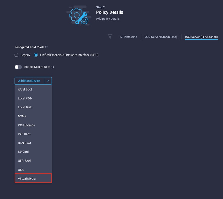
4. For Configured Boot Mode, select Unified Extensible Firmware Interface (UEFI).
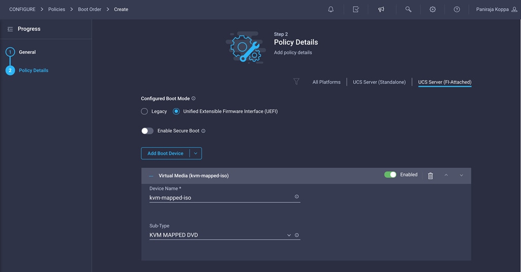
5. From the Add Boot Device drop-down menu, choose Virtual Media.
6. Provide a device name (for example, kvm-mapped-iso) and then, for the subtype, choose KVM Mapped DVD.
For this validation, all four NetApp controller LIFs will be added as boot options. The four LIFs are named as follows:
◦ NA-FCP-LIF01a: NetApp Controller 1, LIF for Fibre Channel SAN A
◦ NA-FCP-LIF02a: NetApp Controller 2, LIF for Fibre Channel SAN A
◦ NA-FCP-LIF01b: NetApp Controller 1, LIF for Fibre Channel SAN B
◦ NA-FCP-LIF02b: NetApp Controller 2, LIF for Fibre Channel SAN B
7. From the Add Boot Device drop-down menu, choose SAN Boot.
8. Provide the device name (for example, NA-fcp-lif01a) and the Logical Unit Number (LUN) value (for example, 0).
9. Provide an interface name (for example, vHBA-A) and note this name for use later in the vHBA definition. This value is important and should match the vHBA name.
Note: vHBA-A is used for NA-fcp-lif01a and NA-fcp-lif02a, and vHBA-B is used for NA-fcp-lif01b and NA-fcp-lif02b.
10. Add the appropriate World Wide Port Name (WWPN) as the target WWPN. You can obtain this value from NetApp after logging in and entering the following command on the NetApp controller: network interface show -vserver <vserver name>.
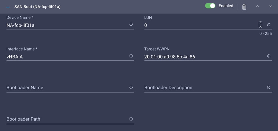
11. Click Create.
12. Repeat these steps three more times to add all the NetApp LIFs. You can rearrange the policies using the arrow keys if needed.
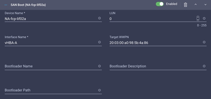
Configuration for NA-fcp-lif02a:
Configuration for NA-fcp-lif01b:

Configuration for NA-fcp-lif02b:
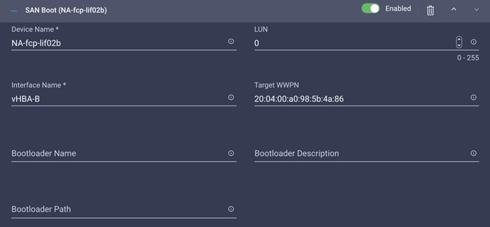
After you have added all the boot devices, they should be listed on the Policy Details screen.
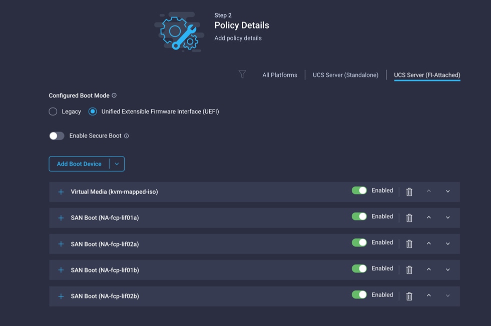
13. Click Create.
14. Click Next.
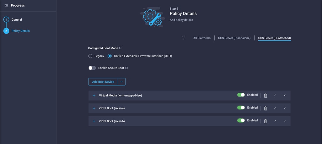
Creating boot-order policy for iSCSI boot from SAN
Follow these steps to configure boot-order policy for iSCSI boot from SAN:
1. Click Select Policy next to BIOS Configuration and then, in the pane on the right, click Create New.
2. Choose the organization from the drop-down menu (for example, FlexPod) and provide a name for the policy (for example, AA04-6454-iSCSI-BootPol).
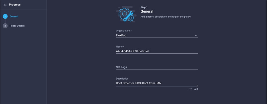
3. Click Next.
4. For Configured Boot Mode, select Unified Extensible Firmware Interface (UEFI).
5. From the Add Boot Device drop-down menu, choose Virtual Media.
6. Provide a device name (for example, ISO) and then, for the subtype, choose KVM Mapped DVD.
For this validation, two iSCSI interfaces (iscsi-a and iscsi-b) will be added as boot options. These interfaces with the same name will be created as part of LAN connectivity policy.
7. From the Add Boot Device drop-down menu, choose iSCSI Boot.
8. For Device Name and Interface Name, enter iscsi-a.
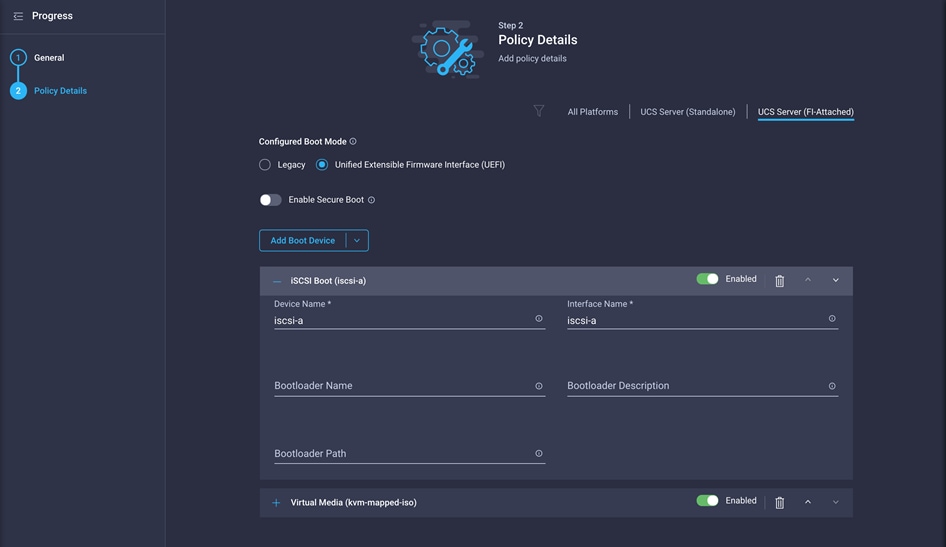
9. Repeat steps 7 and 8 for interface iscsi-b.
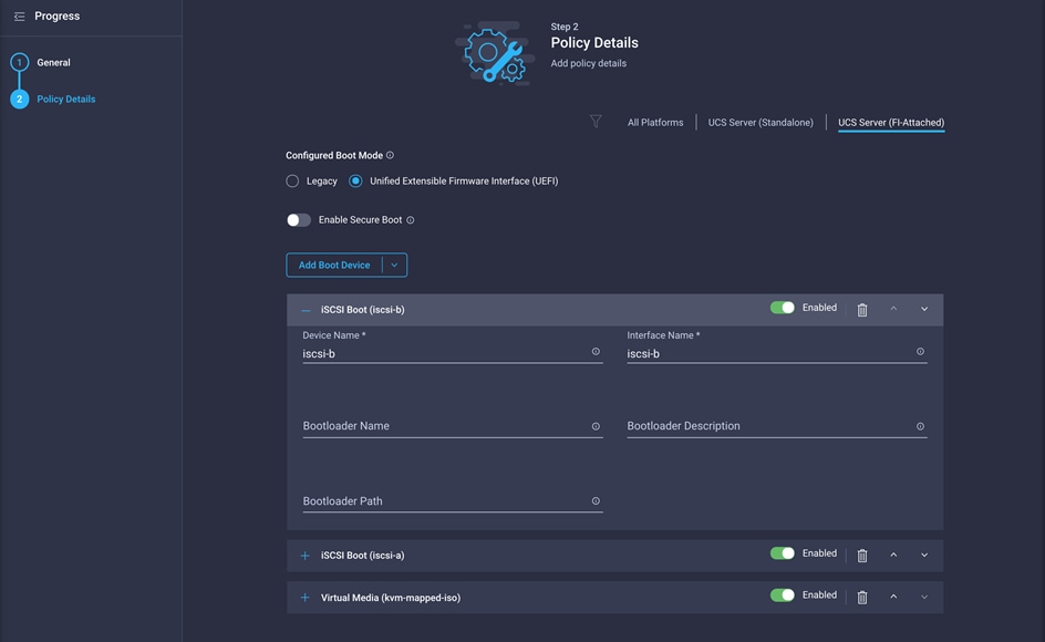
10. Click Create.
After you have added all the boot devices, they should be listed on the Policy Details screen.
11. Click Next.
Step 4: Management Configuration
Next, configure management policy.
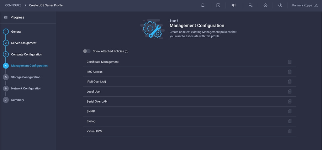
Configure Cisco IMC access policy
Follow these steps to configure Cisco IMC access policy:
1. Click Select Policy next to IMC Access and then, in the pane on the right, click Create New.
2. Choose the organization from the drop-down menu (for example, FlexPod) and provide a name for the policy (for example, AA04-6454-IMCPol).
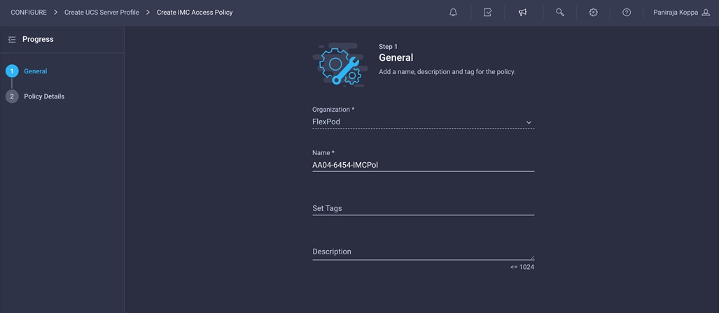
3. Click Next.
4. Provide the in-band (or out-of-band) management VLAN ID (for example, 511). Also make sure that All Platforms is selected because you will need this policy while creating the chassis profile as well.
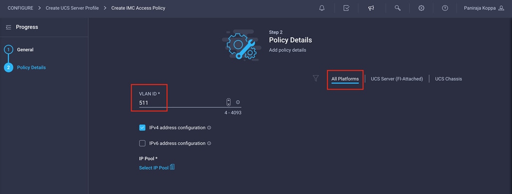
5. Select “Configure IPv4 address configuration” and click Select IP Pool to define a KVM IP address assignment pool.
6. Click Create New in the menu on the right.
7. Choose the organization from the drop-down menu (for example, FlexPod) and provide a name for the policy (for example, AA04-6454-IP-Pool).
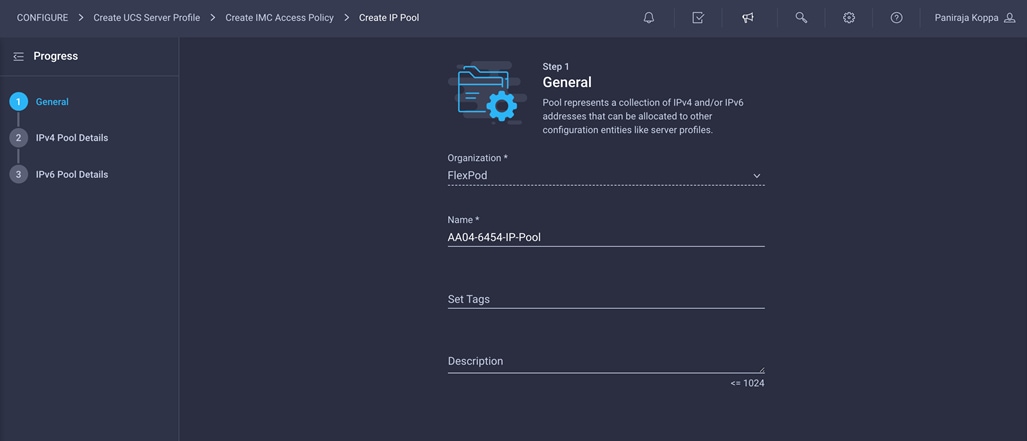
8. Select Configure IPv4 Pool and provide the information to define a pool for KVM IP address assignment.
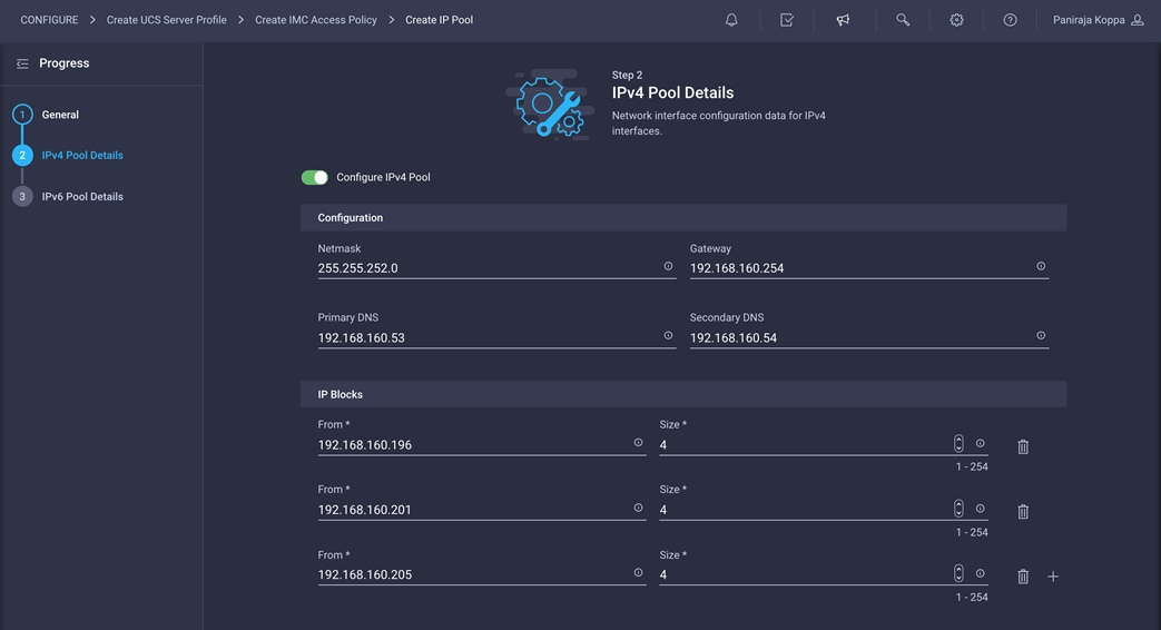
Note: The management IP pool subnet should be accessible from the host that is trying to open the KVM connection. In the example shown here, the hosts trying to open a KVM connection would need to be able to route to 192.168.160.0 subnet.
9. Click Next.
10. Unselect Configure IPv6 Pool.
11. Click Create to finish configuring the IP address pool.
12. Click Create to finish configuring the IMC access policy.
Follow these steps to configure local user policy:
1. Click Select Policy next to Local User and the, in the pane on the right, click Create New.
2. Choose the organization from the drop-down menu (for example, FlexPod) and provide a name for the policy (for example, AA04-6454-LocalUser-Pol).
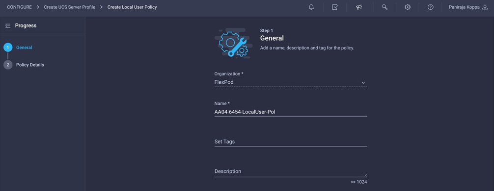
3. Verify that UCS Server (FI-Attached) is selected.
4. Verify that Enforce Strong Password is selected.
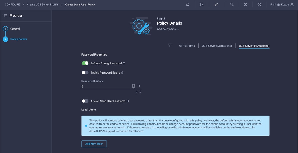
5. Click Add New User.
6. Provide the username (for example, flexpodadmin), choose a role (for example, admin), and provide a password.
Note: The username and password combination defined here will be used to log in to KVMs. The typical Cisco UCS admin username and password combination cannot be used for KVM access.
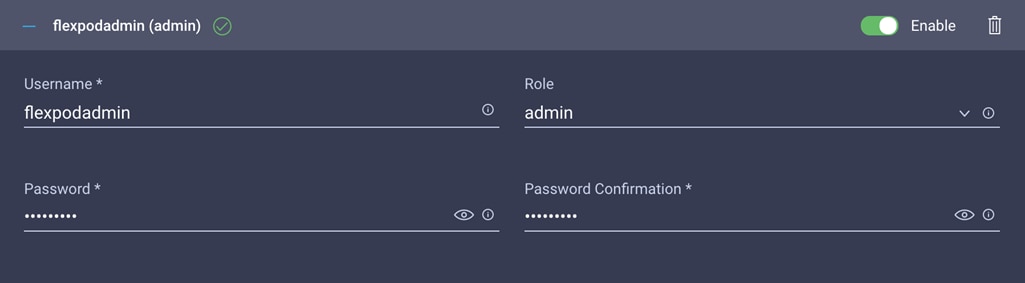
7. Click Create to finish configuring the user.
8. Click Create to finish configuring local user policy.
9. Click Next.
Click Next on the Storage Configuration screen. You will not make any changes to this configuration.
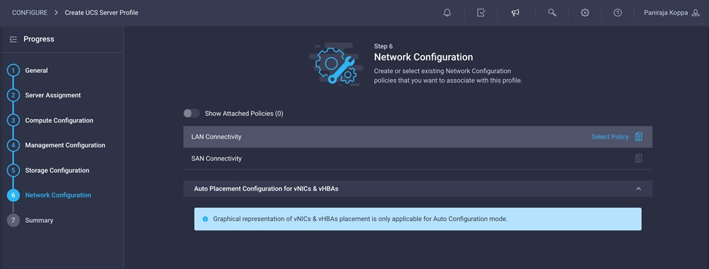
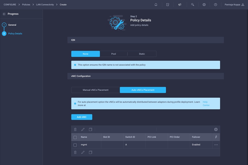
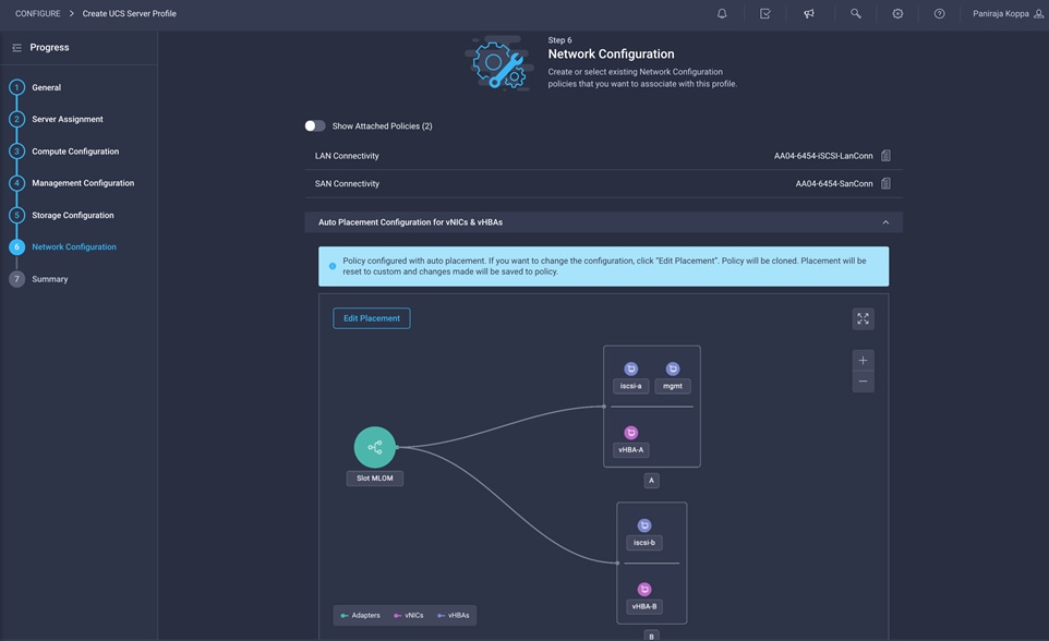
Step 6a: Network Configuration > LAN Connectivity
LAN connectivity policy defines the connections and network communication resources between the server and the LAN on the network. This policy uses pools to assign MAC addresses to servers and to identify the vNICs that the servers use to communicate with the network.
The LAN connectivity policy requires you to create Ethernet network policy, Ethernet adapter policy, and Ethernet QoS policy. When you attach a LAN connectivity policy to a server profile, the addresses of the MAC address pool, or the static MAC address, are automatically assigned.
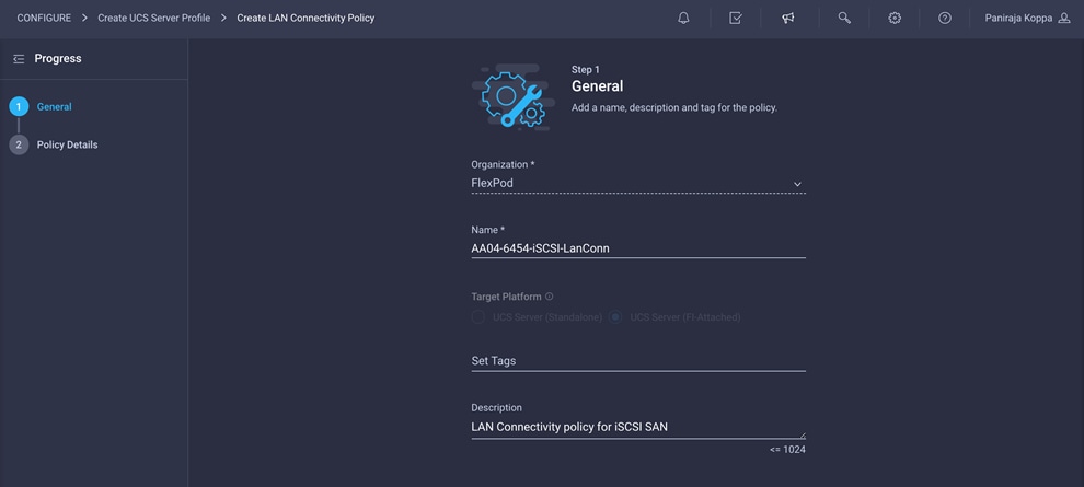
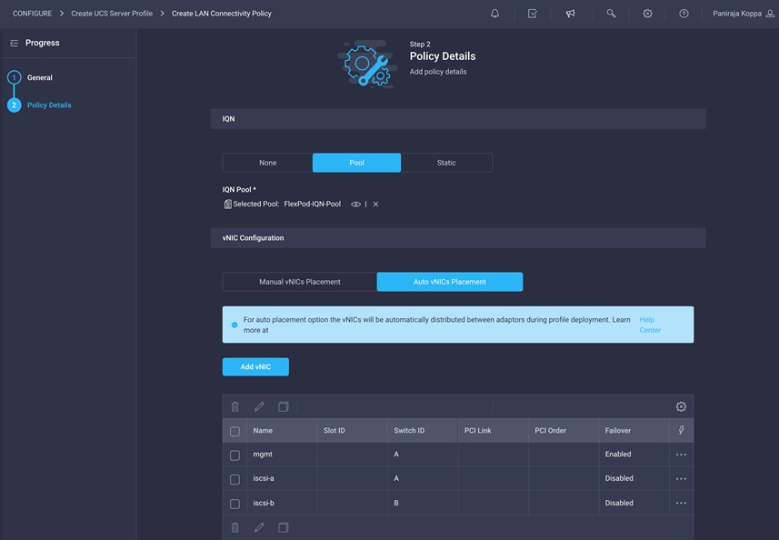
Configure LAN connectivity policy for iSCSI boot
Follow these steps to define LAN connectivity if you are using iSCSI SAN.
1. Click Select Policy next to LAN Connectivity and then, in the pane on the right, click Create New.
2. Choose the organization from the drop-down menu (for example, FlexPod) and provide a name for the policy (for example, AA04-6454-iSCSI-LanConn).
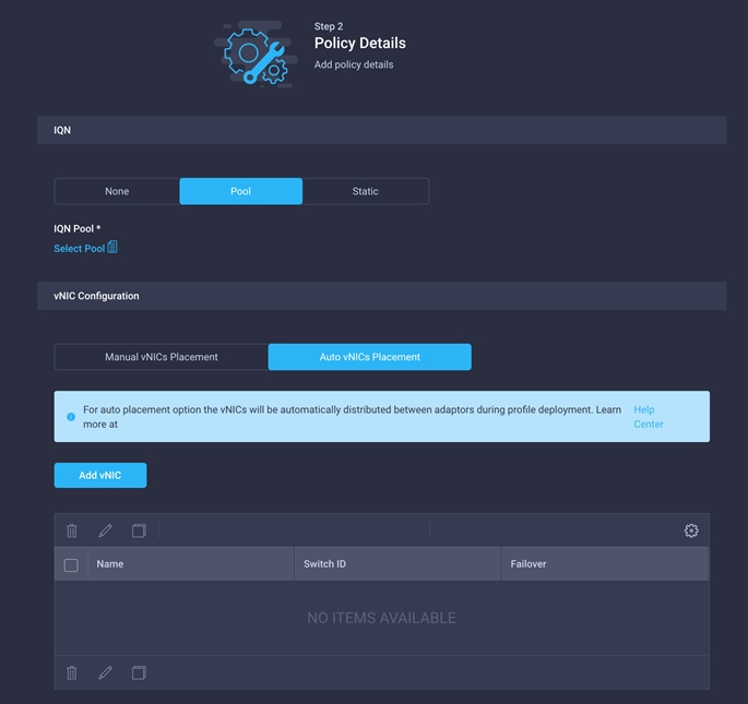
This deployment uses three vNICs, as follows:
◦ mgmt: Fabric Interconnect A vNIC for management and NFS VLANs
◦ iscsi-a: Fabric Interconnect A vNIC for iSCSI
◦ iscsi-b: Fabric Interconnect B vNIC for iSCSI
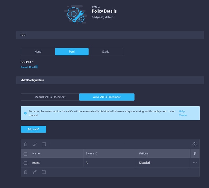
3. For the iSCSI qualified name (IQN), select Pool.
4. To keep the vNIC placement simple, select Auto vNIC Placement for vNIC configuration.
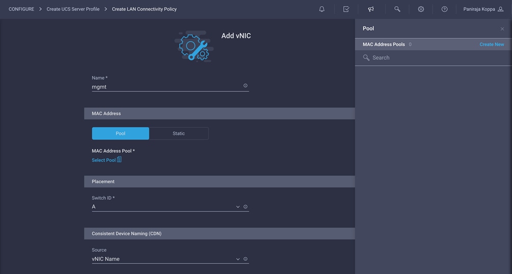
5. Click Add vNIC.
6. Provide the name of the vNIC (for example, mgmt).
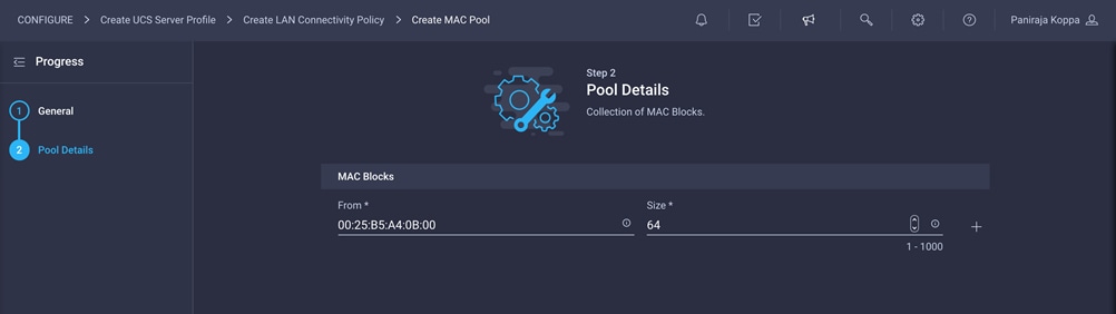
Create the MAC address pool for Fabric A
The MAC address pool has not been defined yet, so a new MAC address pool will be created now for Fabric A. This pool will be reused for all future Fabric-A vNICs.
1. Click Select Pool under MAC Address Pool and then, in the pane on the right, click Create New.
2. Choose the organization from the drop-down menu (for example, FlexPod) and provide a name for the policy (for example, MAC-Pool-A).
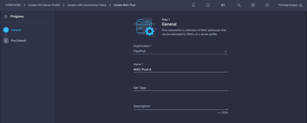
3. Click Next.
4. Provide the starting MAC address. The recommended prefix for MAC addresses is 00:25:B5:xx:xx:xx. As a best practice, in FlexPod some additional information is always coded into the MAC address pool for ease of troubleshooting. For example, in the starting address 00:25:B5:A4:0A:00, A4 is the rack ID and 0A indicates Fabric A.
5. Provide the size of the MAC address pool (for example, 64).
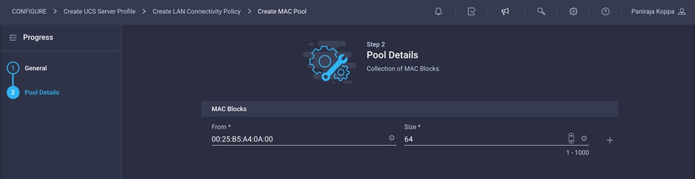
6. Click Create to finish creating the MAC address pool.
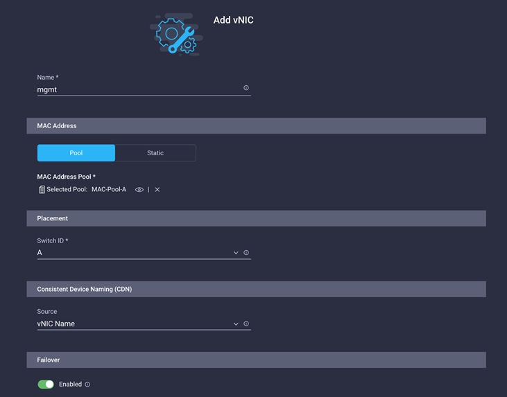
7. Back in the Add vNIC window, from the drop-down menu, choose A as the switch ID.
8. For Consistent Device Naming (CDN), from the drop-down menu, choose vNIC Name.
9. Verify that Failover is enabled.
Create Ethernet network group policy
The Ethernet policies have not been created yet, so these policies will be created now. These policies will be reused when additional vNICs are defined.
Ethernet network group policy defines the VLANs allowed for a particular vNIC. Three network group policies will be defined for this deployment:
● Management network group policy, to define the VLANs for management and NFS traffic
● iSCSI-A network group policy, to define the VLANs for iSCSI on Fabric A
● iSCSI-B network group policy, to define the VLANs for iSCSI on Fabric B
1. Click Select Policy under Ethernet Network Group Policy and then, in the pane on the right, click Create New.
2. Choose the organization from the drop-down menu (for example, FlexPod) and provide a name for the policy (for example, Mgmt-NetGrp-Pol).
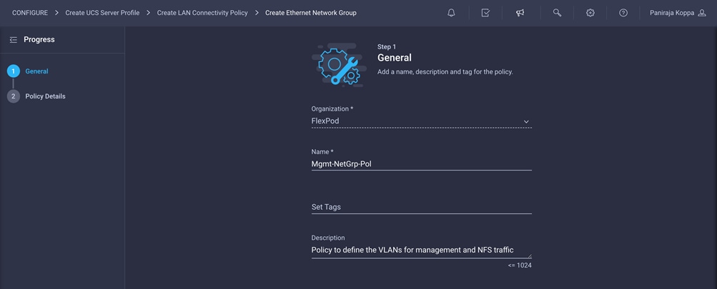
3. Click Next.
4. Enter the allowed VLANs (for example, 2,511,3050) and the native VLAN ID (for example, 2).
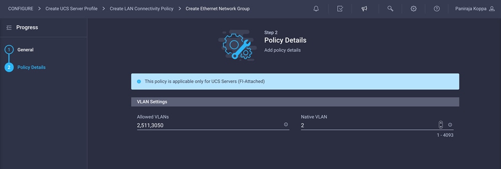
5. Click Create to finish configuring the Ethernet network group policy.
Create Ethernet network control policy
Ethernet network control policy is used to enable Cisco Discovery Protocol (CDP) and Link Layer Discovery Protocol (LLDP) for the vNICs. A single policy will be created here and reused for all the vNICs.
1. Click Select Policy under Ethernet Network Control Policy and then, in the pane on the right, click Create New.
2. Choose the organization from the drop-down menu (for example, FlexPod) and provide a name for the policy (for example, Enable-CDP-LLDP).

3. Click Next.
4. Enable Cisco Discovery Protocol and both Transmit and Receive under LLDP.
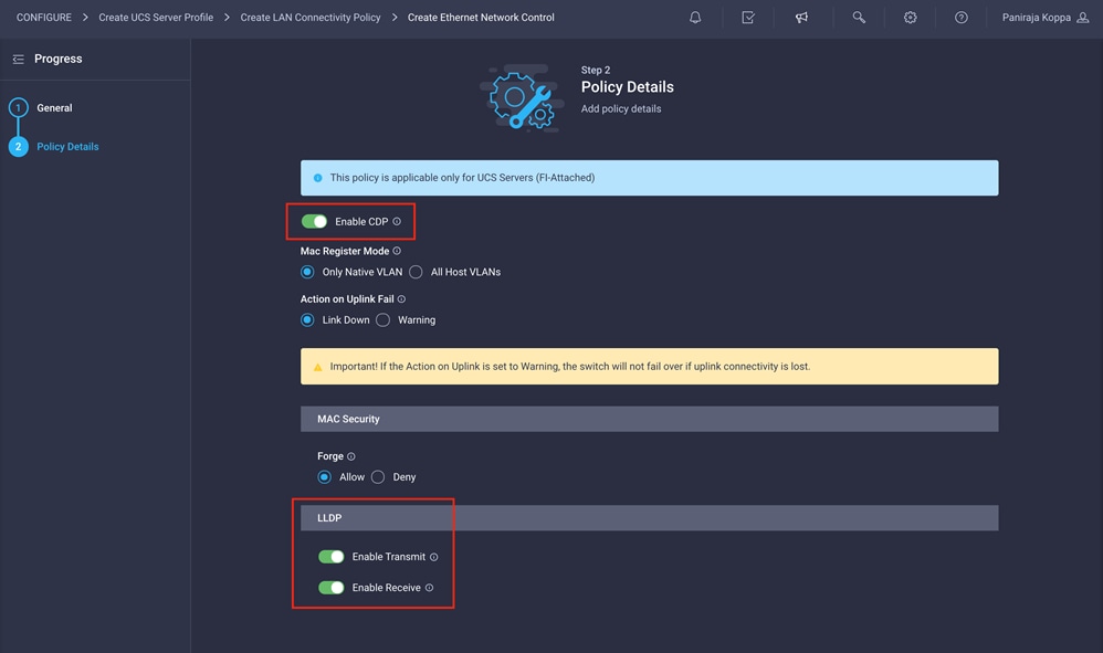
5. Click Create to finish creating Ethernet network control policy.
Create Ethernet QoS policy
Ethernet QoS policy is used to enable jumbo maximum transmission units (MTUs) for all the vNICs. A single policy will be created and reused for all the vNICs.
1. Click Select Policy under Ethernet QoS and in then, the pane on the right, click Create New.
2. Choose the organization from the drop-down menu (for example, FlexPod) and provide a name for the policy (for example, Jumbo-MTU-QoS).
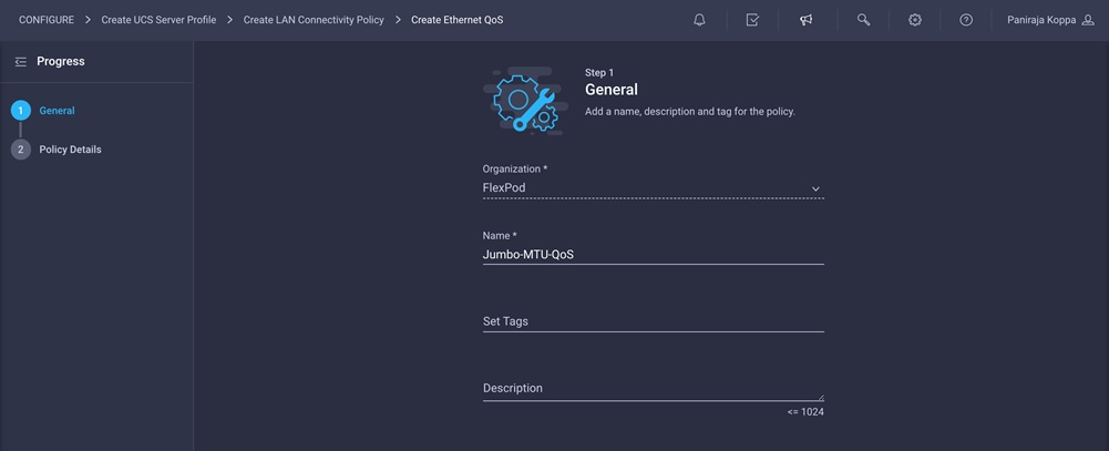
3. Click Next.
4. Change the MTU, Bytes value to 9000.
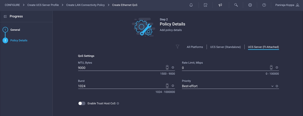
5. Click Create to finish setting up the Ethernet QoS policy.
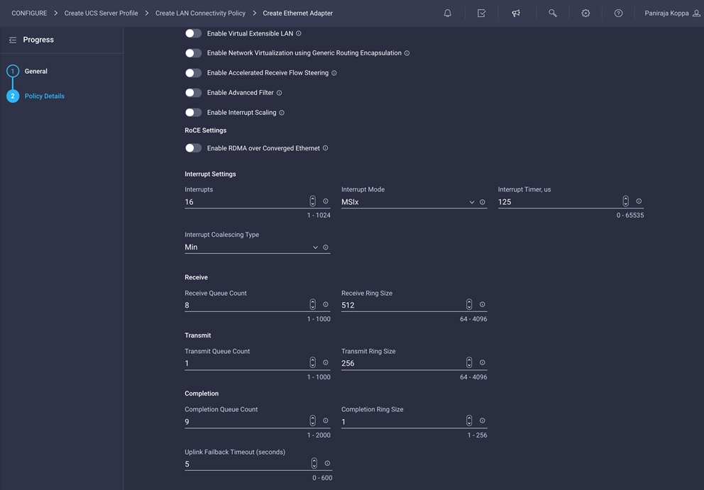
Create Ethernet adapter policy
Ethernet adapter policy is used to set the interrupts and the send and receive queues. The values are set according to the best-practices guidance for the operating system in use.
1. Click Select Policy under Ethernet Adapter and then, in the pane on the right, click Create New.
2. Choose the organization from the drop-down menu (for example, FlexPod) and provide a name for the policy (for example, RHEL-Ether-AdapterPol).
3. Click Ethernet Adapter Default Configuration and choose Linux.
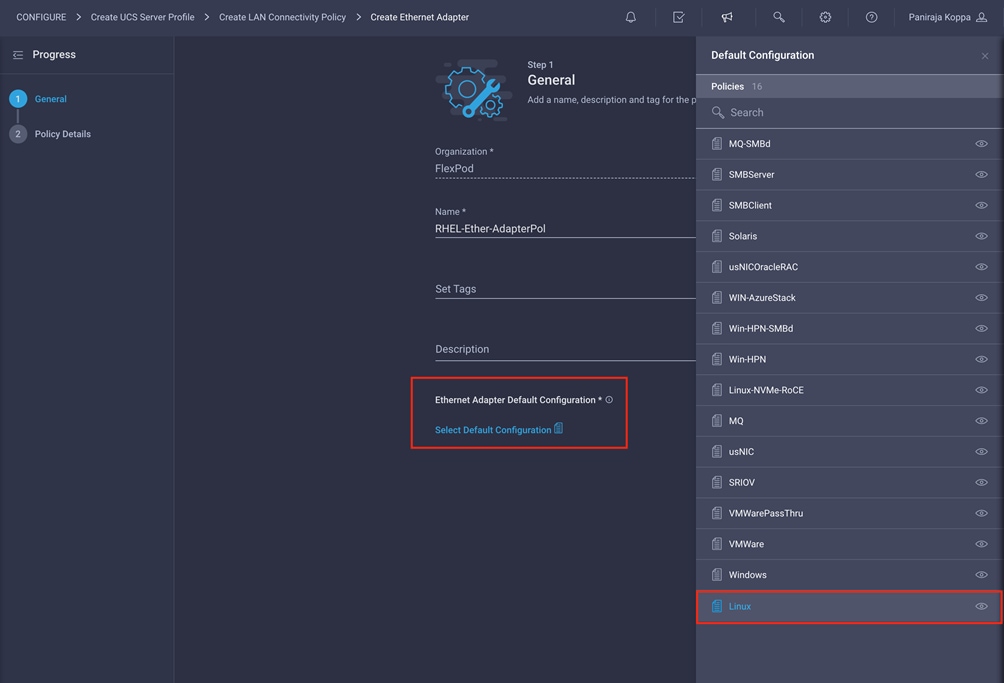
4. Change the Interrupts, Receive Queue Count, Transmit Queue Count, and Completion Queue Count values to 16, 8, 1, and 9, respectively, as shown here:
5. Verify that all the policies are assigned to vNIC mgmt.
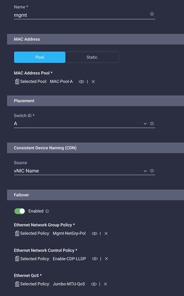
6. Click Add to add the vNIC.
Add iSCSI vNICs to LAN connectivity policy
Note: Repeat all the step under Step 6a: Network Configuration > LAN Connectivity to create additional vNICs. Most of the policies created for the mgmt vNIC will be reused for the remaining vNICs (iscsi-a and iscsi-b).
You will map iSCSI-a to Fabric Interconnect A, and you will use the MAC address pool created previously. It can also use Ethernet network control, Ethernet QoS, and Ethernet adapter policies. It uses a different network group policy. You will map iSCSI-b to Fabric Interconnect B, and you can create a MAC address pool dedicated to Fabric Interconnect B. It also needs a different network group policy. It can use existing Ethernet network control, Ethernet QoS, and Ethernet adapter policies.
The MAC pool and network group policies used for subsequent vNICS are discussed in the following steps.
1. When adding the iscsi-a vNIC, click Select Policy under Ethernet Network Group Policy and click Create New in the pane on the right. Select the organization (for example, FlexPod) and provide a name (for example, iSCSI-A-NetGrp-Pol).
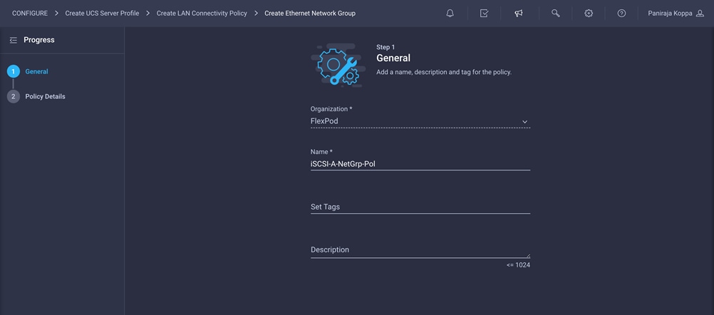
2. Enter the allowed VLANs (for example, 3010) and the native VLAN ID (for example, 3010).
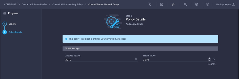
3. Click Create to finish configuring the Ethernet network group policy.
4. When adding the iscsi-b vNIC, click Select Pool under MAC Address Pool and click Create New in the pane on the right. Select the organization (for example, FlexPod) and provide a name (for example, MAC-Pool-B).
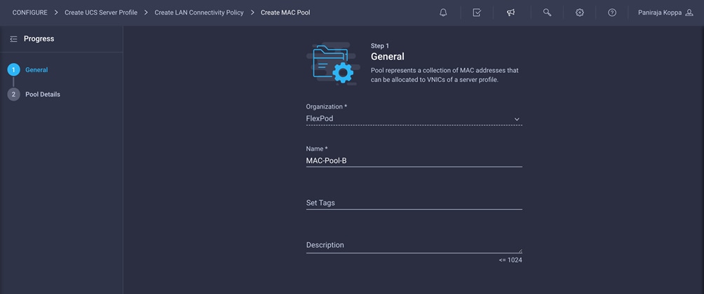
5. Note that the same prefix, 00:25:B5, is used for MAC Pool B, but 0B in the second-to-the-last octet signifies the these MAC addresses are assigned to vNICs associated with Fabric B.
6. Click Create to finish creating the MAC address pool.
7. Click Select Policy under Ethernet Network Group Policy and click Create New in the pane on the right. Select the organization (for example, FlexPod) and provide a name (for example, iSCSI-B-NetGrp-Pol).

8. Enter the allowed VLANs (for example, 3020) and the native VLAN ID (for example, 3020).
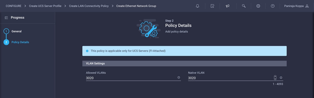
9. Click Create to finish configuring the Ethernet network group policy.
Add iSCSI boot policy to iSCSI vNICs
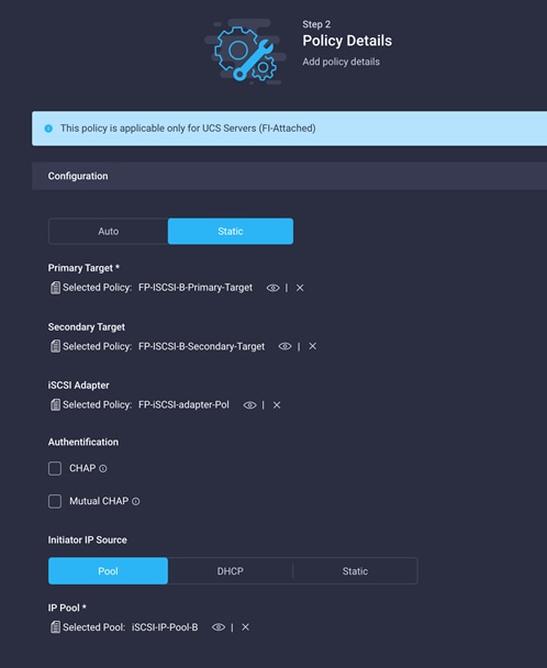
iSCSI vNICs need an attached iSCSI boot policy if you are planning to use iSCSI boot from SAN. If iSCSI boot from SAN is not required and you are planning to use iSCSI storage in the operating system, then you do not need to attach the iSCSI boot policies to iSCSI vNICs. In the validation presented here, two targets—primary and secondary—are mapped per vNIC, and hence you will have four paths to the boot LUN.
Follow the steps here to create and attach iSCSI boot policies to iSCSI vNICs.
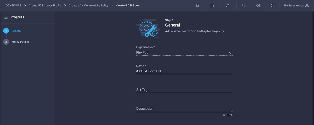
1. When adding the iscsi-a vNIC, click Select Policy under iSCSI Boot and click Create New in the pane on the right. Select the organization (for example, FlexPod) and provide a name (for example, iSCSI-A-Boot-Pol).
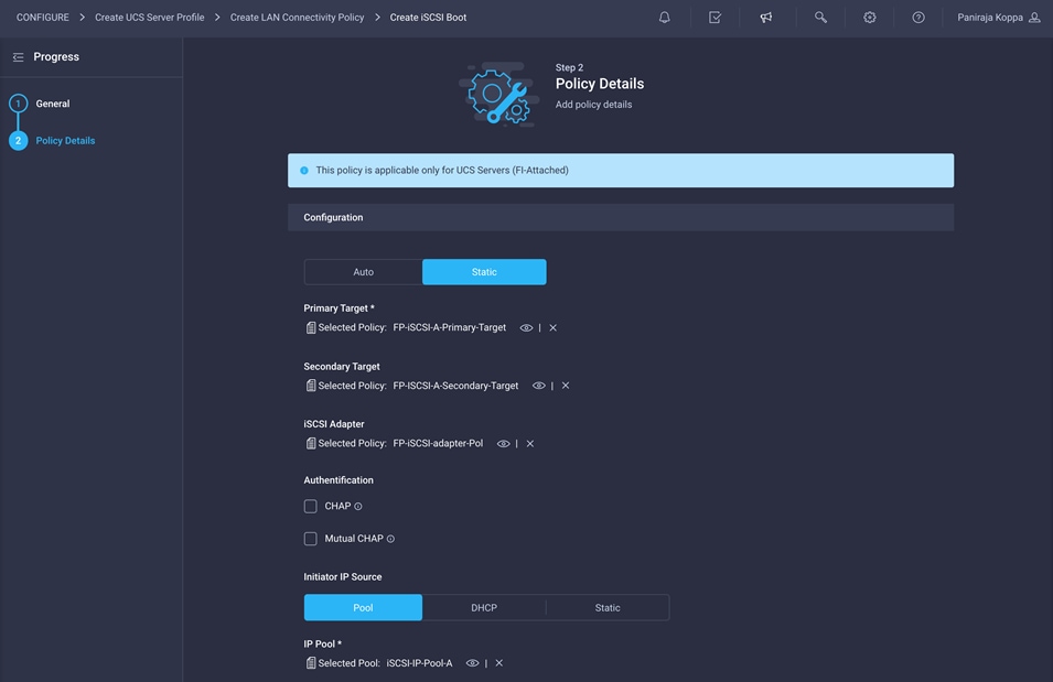
2. For Policy Details > Configuration, select Static.
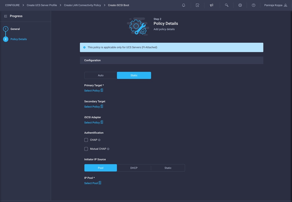
3. Click Select Policy under Primary Target and click Create New in the pane on the right. Select the organization (for example, FlexPod) and provide a name (for example, FP-iSCSI-A-Primary-Target).
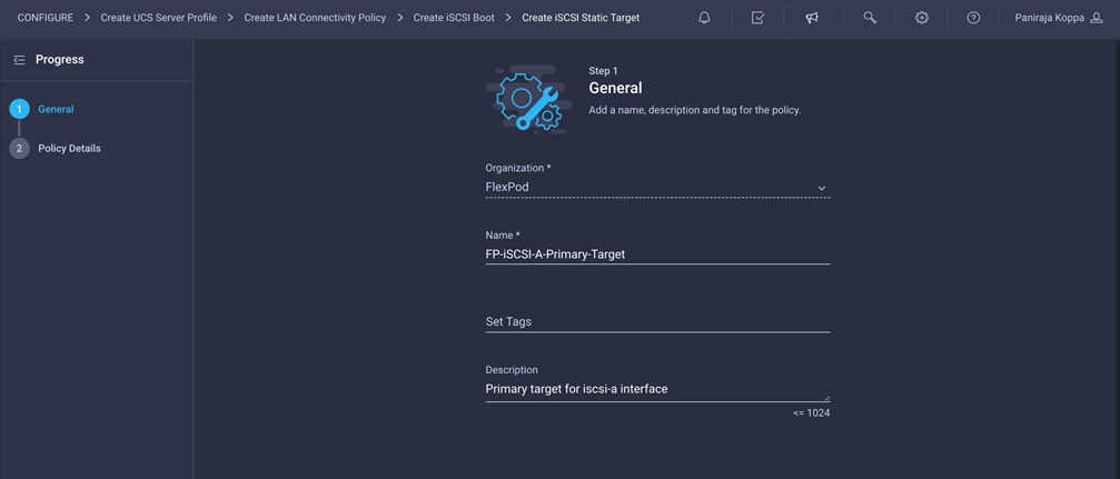
4. Enter the target configuration for the primary target.
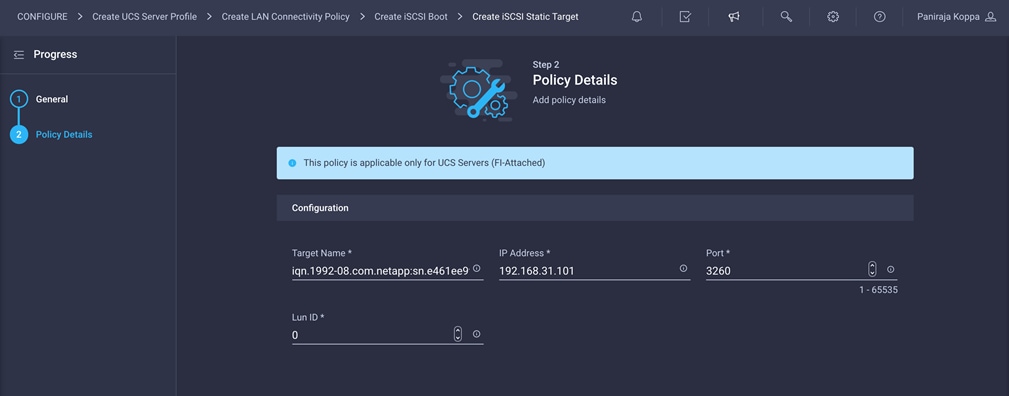
5. Click Create.
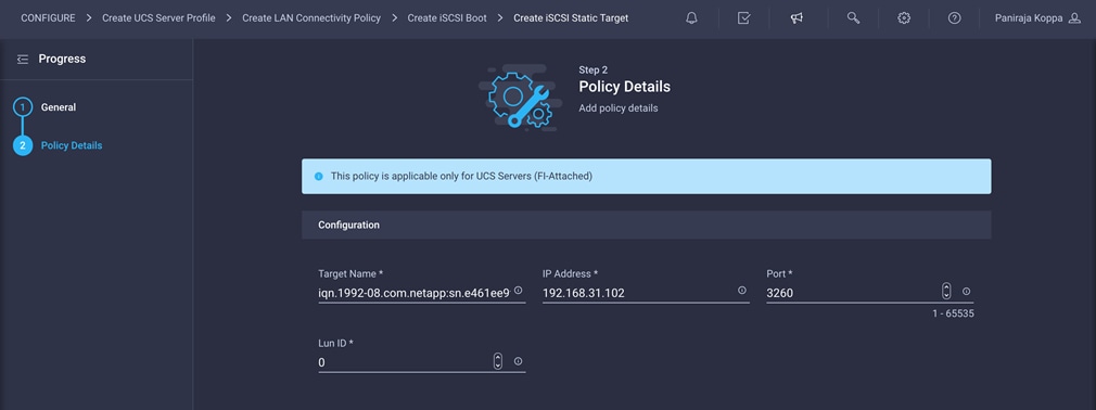
6. Repeat the steps 3, 4, and 5 for the secondary target, naming the target, for example, FP-iSCSI-A-Secondary-Target.
7. Click Select Policy under iSCSI Adapter and click Create New in the pane on the right. Select the organization (for example, FlexPod) and provide a name (for example, FP-iSCSI-adapter-Pol).
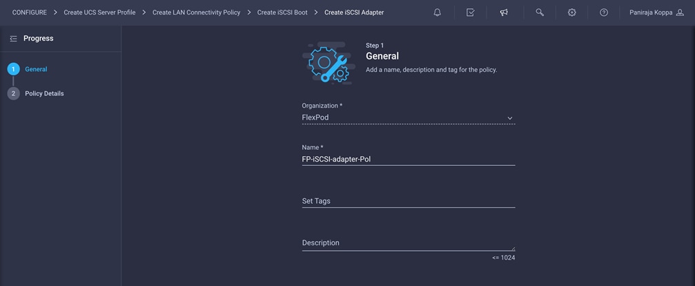
8. This document retains the default configuration. Change the configuration if required.
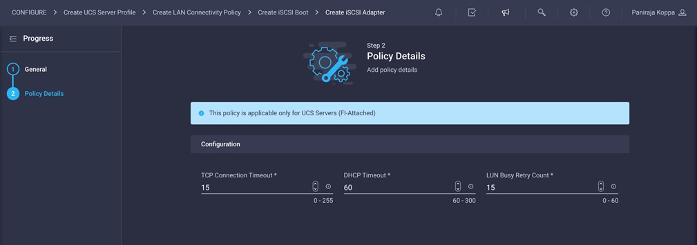
9. Click Create.
10. Configure authentication as CHAP or Mutual CHAP.
11. Make sure that Pool is selected under Initiator IP Source.
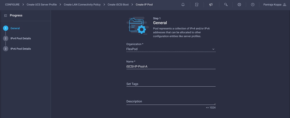
12. Click Select Pool under IP Pool and click Create New in the pane on the right. Select the organization (for example, FlexPod) and provide a name (for example, iSCSI-IP-Pool-A).
13. Select Configure IPv4 Pool and provide the information to define a pool for iSCSI IP address assignment.
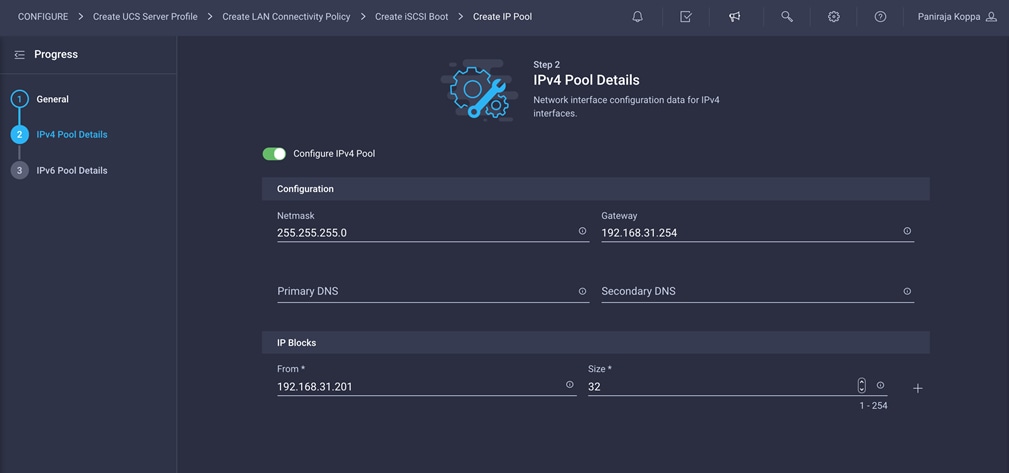
14. Click Next.
15. Deselect Configure IPv6 Pool.
16. Click Create to finish configuring the IP address pool.
17. Click Create to complete creating the iSCSI boot policy for the iscsi-a vNIC.
18. For iscsi-b, create another iSCSI boot policy (for example, iSCSI-B-Boot-Pol) with a different primary target, secondary target, and IP address pool. You can use the iSCSI adapter policy created earlier.
Add the IQN pool for LAN connectivity policy
The last step is to add an IQN pool. Note that you add an IQN pool only if you are using an iSCSI SAN. If you are using only Fibre Channel SANs, you do not need to create and map IQN policy.
Follow these steps to create and attach an IQN pool to the LAN connectivity policy.
1. Click Select Pool under IQN Pool and click Create New in the pane on the right. Select the organization (for example, FlexPod) and provide a name (for example, FlexPod-IQN-Pool).
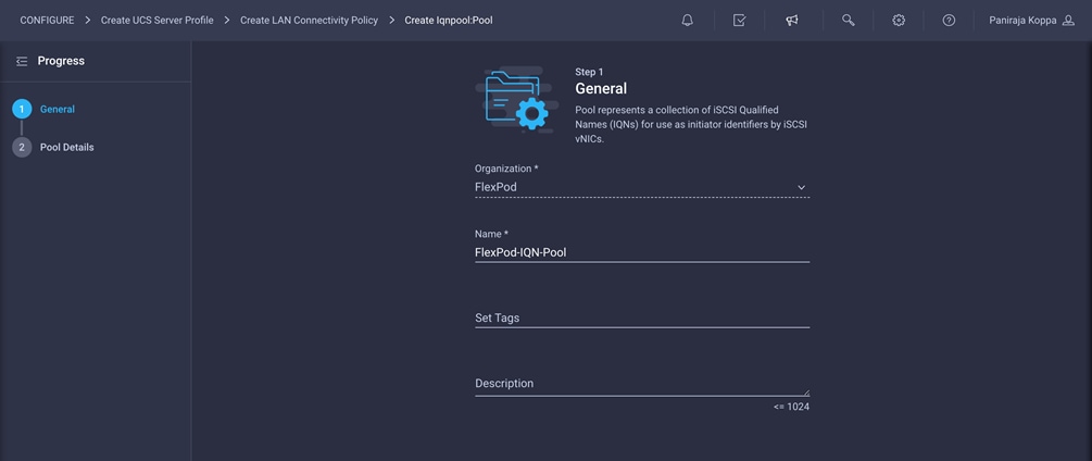
2. Provide the information to define a pool for iSCSI IP address assignment. For FlexPod, the recommended approach is to use iqn.2010-11.com.flexpod as the prefix and ucs-host as the suffix. Also, if multiple Cisco UCS domains are in use, a more specific suffix, such as AA04-6454-host, can also be used.
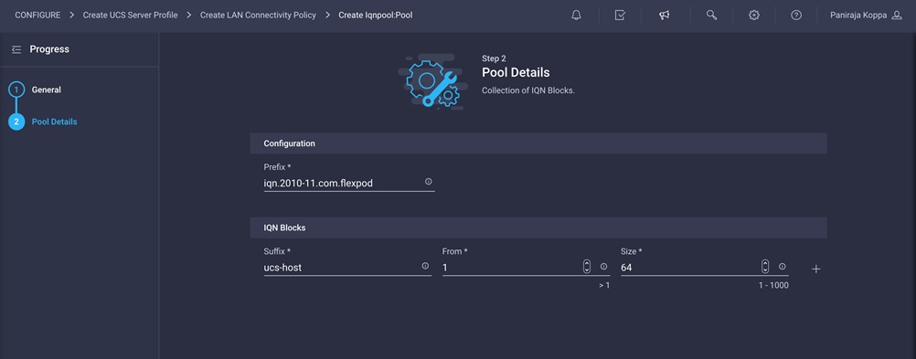
3. Click Create.
4. Verify that all the vNICs have been added successfully before moving on to create SAN connectivity policy.
Create LAN connectivity policy for Fibre Channel boot
If you are planning to deploy only Fibre Channel SANs and are not planning to use any iSCSI SAN at all, then you do not need to create iSCSI vNICs and map an IQN policy to the LAN connectivity policy. Note that the boot policies also differ for Fibre Channel and iSCSI.
Summary of LAN connectivity policies
Table 2 summarizes the LAN connectivity policy for iSCSI used in this validation.
Table 2. LAN connectivity policy for iSCSI
| Interface |
Placement |
Failover |
MAC address pool |
Network policies |
iSCSI boot policy |
IQN Pool |
| mgmt |
Fabric Interconnect A |
Enabled |
MAC-Pool-A |
Mgmt-NetGrp-Pol Enable-CDP-LLDP Jumbo-MTU-QoS RHEL-Ether-AdapterPol |
|
FlexPod-IQN-Pool |
| iscsi-a |
Fabric Interconnect A |
Disabled |
MAC-Pool-A |
iSCSI-A-NetGrp-Pol Enable-CDP-LLDP Jumbo-MTU-QoS RHEL-Ether-AdapterPol |
iSCSI-A-Boot-Pol |
|
| iscsi-b |
Fabric Interconnect B |
Disabled |
MAC-Pool-B |
iSCSI-B-NetGrp-Pol Enable-CDP-LLDP Jumbo-MTU-QoS RHEL-Ether-AdapterPol |
iSCSI-B-Boot-Pol |
Table 3 lists details of the iSCSI boot policy associated with the iSCSI interfaces used in this validation.
Table 3. iSCSI boot policy associated with iSCSI interfaces
| iSCSI boot policy |
IP address pool |
iSCSI targets |
| iSCSI-A-Boot-Pol |
iSCSI-IP-Pool-A |
FP-iSCSI-A-Primary-Target FP-iSCSI-A-Secondary-Target |
| iSCSI-B-Boot-Pol |
iSCSI-IP-Pool-B |
FP-iSCSI-B-Primary-Target FP-iSCSI-B-Secondary-Target |
Table 4 summarizes the LAN connectivity policy when only Fibre Channel is used for this validation.
Table 4. LAN connectivity policy when only Fibre Channel is used
| Interface |
Placement |
Failover |
MAC address pool |
Network policies |
| mgmt |
Fabric Interconnect A |
Enabled |
MAC-Pool-A |
Mgmt-NetGrp-Pol Enable-CDP-LLDP Jumbo-MTU-QoS RHEL-Ether-AdapterPol |
Step 6b: Network Connectivity > SAN Connectivity
A SAN connectivity policy determines the network storage resources and the connections between the server and the storage device on the network. This policy enables you to configure the vHBAs that the servers use to communicate with the SAN.
Include SAN connectivity policy only if you have Fibre Channel SAN. This policy is not required if you just have iSCSI SAN.
1. Click Select Policy next to SAN Connectivity and then, in the pane on the right, click Create New.
2. Choose the organization from the drop-down menu (for example, FlexPod) and provide a name for the policy (for example, AA04-6454-SanConn).
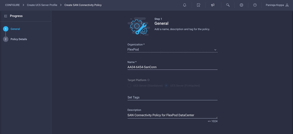
This deployment uses two vHBAs, as follows:
◦ vHBA-A: Fabric Interconnect A vHBA for SAN A
◦ vHBA-B: Fabric Interconnect B vHBA for SAN B
3. To keep the vHBA placement simple, select Auto vHBAs Placement. Make sure that Pool is selected for WWNN Address.
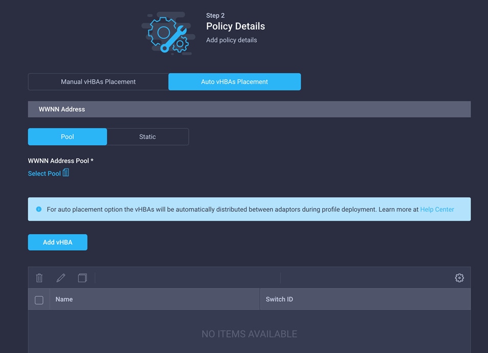
The WWNN address pools have not been defined yet, so you will now create a new WWNN address pool.
1. Click Select Pool under WWNN Address Pool and then, in the pane on the right, click Create New.
2. Choose the organization from the drop-down menu (for example, FlexPod) and provide a name for the policy (for example, WWNN-Pool).
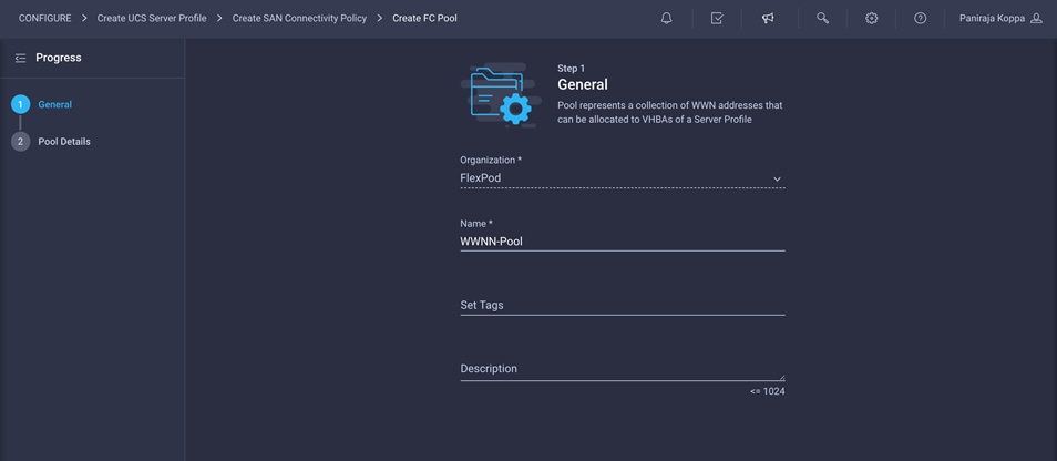
3. Click Next.
4. Provide the starting WWNN block address. The recommended prefix for WWNN addresses is 20:00:00:25:B5:xx:xx:xx. As a best practice, in FlexPod some additional information is always coded into the WWNN address pool for ease of troubleshooting. For example, in the address 20:00:00:25:B5:A4:00:00, A4 is the rack ID.
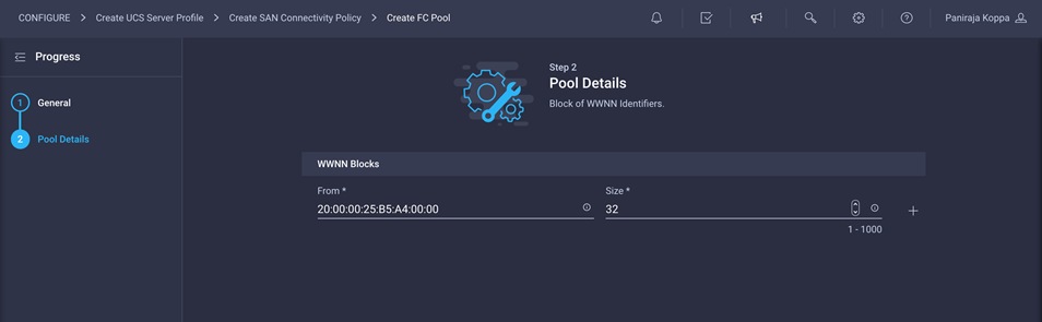
5. Click Create to finish creating the WWNN address pool.
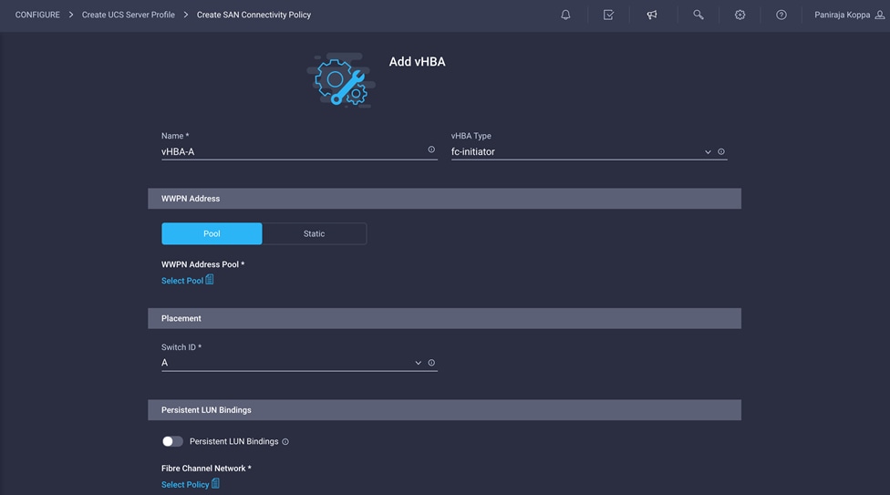
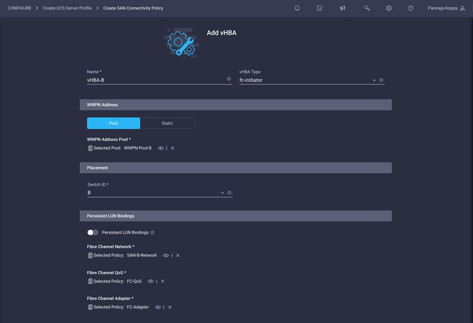
Now create a vHBA for SAN A.
1. Click Add vHBA.
2. Provide the name of the vNIC (for example, vHBA-A).
3. For vHBA Type, choose fc-initiator from the drop-down menu.
4. Choose Switch ID A from the drop-down menu.
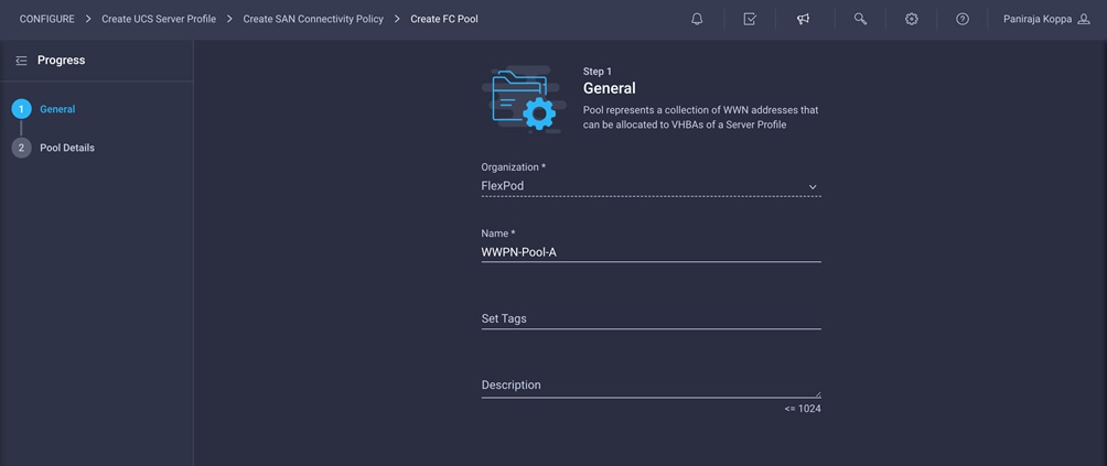
Create the WWPN pool for SAN A
The WWPN address pool has not been defined yet, so you will now create a WWPN address pool for Fabric A.
1. Click Select Pool under WWPN Address Pool and then, in the pane on the right, click Create New.
2. Choose the organization from the drop-down menu (for example, FlexPod) and provide a name for the policy (for example, WWPN-Pool-A).
3. Provide the starting WWPN block address for SAN A. The recommended prefix for WWPN addresses is 20:00:00:25:B5:xx:xx:xx. As a best practice, in FlexPod some additional information is always coded into the WWPN address pool for ease of troubleshooting. For example, in the address 20:00:00:25:B5:A4:0A:00, A4 is the rack ID and 0A signifies SAN A.
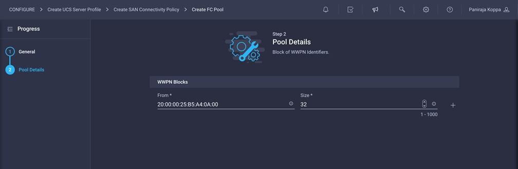
4. Provide a size of the pool.
5. Click Create.
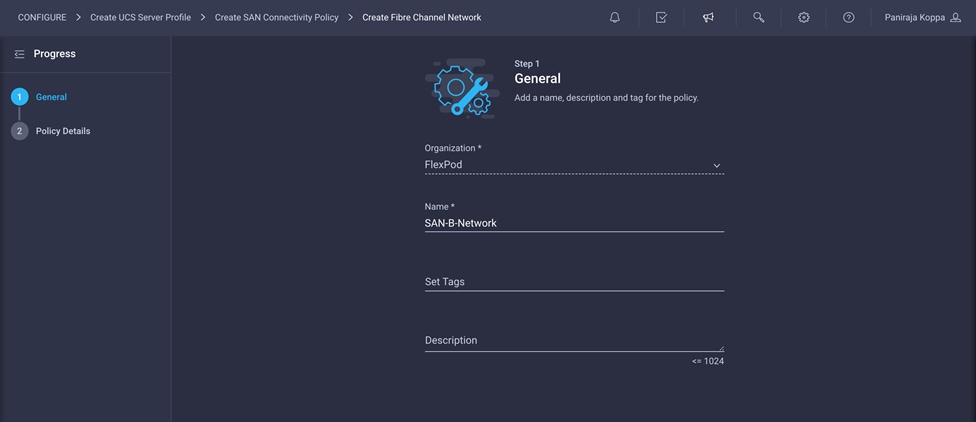
Create Fibre Channel network policy for SAN A
A Fibre Channel network policy governs the VSAN configuration for the virtual interfaces. VSAN 111 will be used for vHBA-A, and VSAN 112 will be used for vHBA-B.
1. Click Select Policy under Fibre Channel Network and then, in the pane on the right, click Create New.
2. Choose the organization from the drop-down menu (for example, FlexPod) and provide a name for the policy (for example, SAN-A-Network).
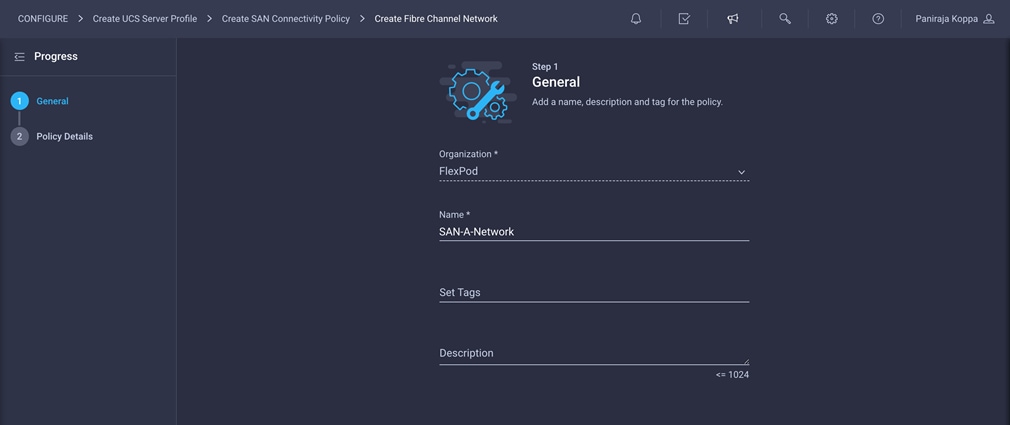
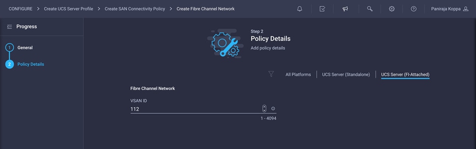
3. For the scope, select UCS Server (FI-Attached).
4. Under Default VLAN, provide the VSAN information (for example, 111).
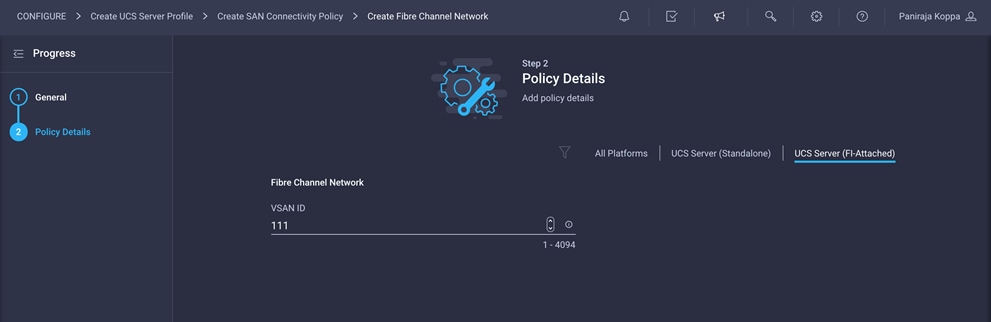
5. Click Create to finish creating the Fibre Channel network policy.
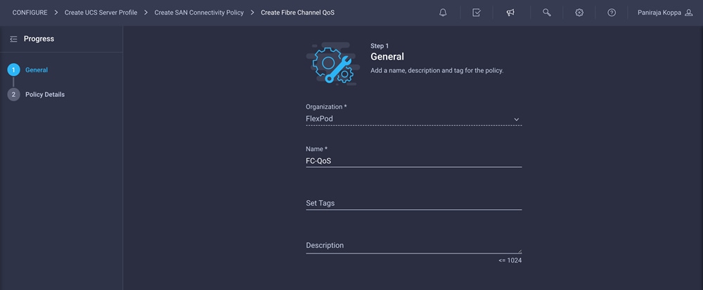
Create Fibre Channel QoS policy
The Fibre Channel QoS policy assigns a system class to the outgoing traffic for a vHBA. This system class determines the quality of service for the outgoing traffic. The Fibre Channel QoS policy used in this deployment uses default values and will be shared by both vHBA-A and vHBA-B.
1. Click Select Policy under Fibre Channel QoS and then, in the pane on the right, click Create New.
2. Choose the organization from the drop-down menu (for example, FlexPod) and provide a name for the policy (for example, FC-QoS).
3. For the scope, select UCS Server (FI-Attached).
4. Do not change the default values on the Policy Details screen.
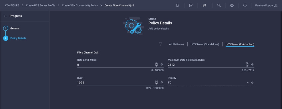
5. Click Create to finish creating the Fibre Channel QoS policy.
Create Fibre Channel adapter policy
A Fibre Channel adapter policy governs the host-side behavior of the adapter, including the way that the adapter handles traffic. This validation uses the default values for the adapter policy, and the policy will be shared by both vHBA-A and vHBA-B.
1. Click Select Policy under Fibre Channel Adapter and then, in the pane on the right, click Create New.
2. Choose the organization from the drop-down menu (for example, FlexPod) and provide a name for the policy (for example, FC-Adapter).
3. Choose Linux for the default configuration for the Fibre Channel adapter.
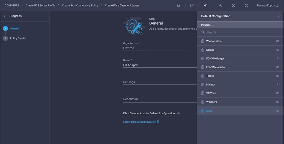
4. For the scope, select UCS Server (FI-Attached).
5. Do not change the default values on the Policy Details screen.
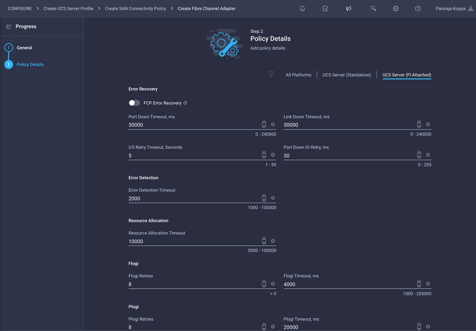
6. Click Create to finish creating the Fibre Channel adapter policy.
7. Click Add to create vHBA-A.
Repeat the preceding steps to add vHBA-B for SAN B.
1. Use switch ID B for this vHBA. The WWPN pool and Fibre Channel network policy (VSAN) for this vHBA are unique, but the Fibre Channel QoS and Fibre Channel adapter policies defined previously for vHBA-A will be reused.
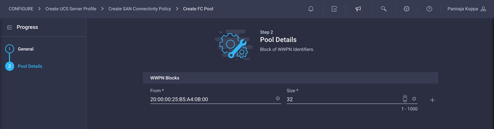
2. Note the WWPN-Pool-B information used for this validation.
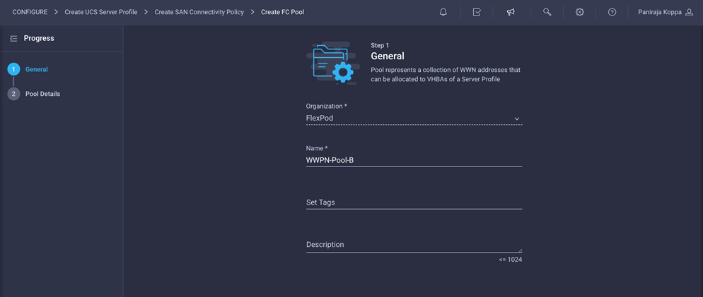
The recommended prefix for WWPN addresses is 20:00:00:25:B5:xx:xx:xx. As a best practice, in FlexPod some additional information is always coded into the WWPN address pool for ease of troubleshooting. For example, in the address 20:00:00:25:B5:A4:0B:00, A4 is the rack ID and 0B signifies SAN B.
3. Note the Fibre Channel network policy for SAN B used in this validation.
4. For the scope, select UCS Server (FI-Attached) and enter the VSAN information (for example, 112) under Default VLAN.
After all the configuration is completed, vHBA-B should look like the following screen:
SAN connectivity policy will be listed as shown on the following screen:
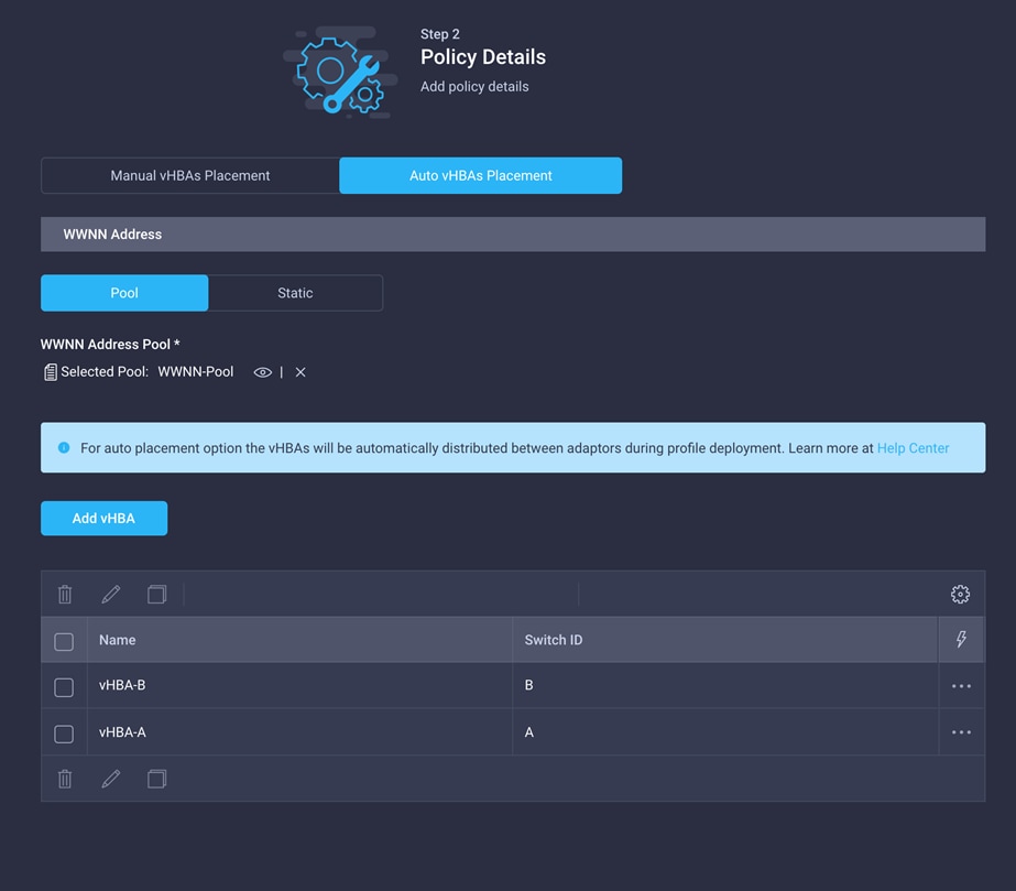
5. After adding all the vNICs and vHBAs, verify their placement by expanding the vNICs and vHBAs Placement option.
5. Click Next.
On the summary screen, verify which policies are mapped to various settings and the status of the server profile. The server profile has not been deployed yet, so the status will be Not Deployed.
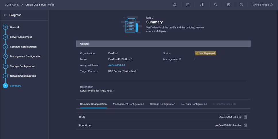
After verifying the settings on the server profile Summary screen, deploy the server profile.
Click Deploy and then Deploy again to deploy the server profile. You would see a task in progress in the top-right corner. You can click the task icon to view the details of the task in progress.
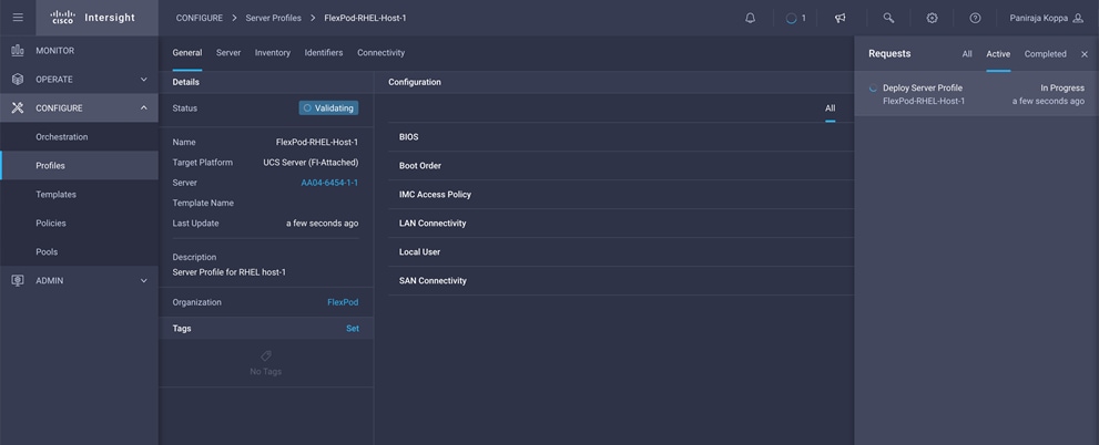
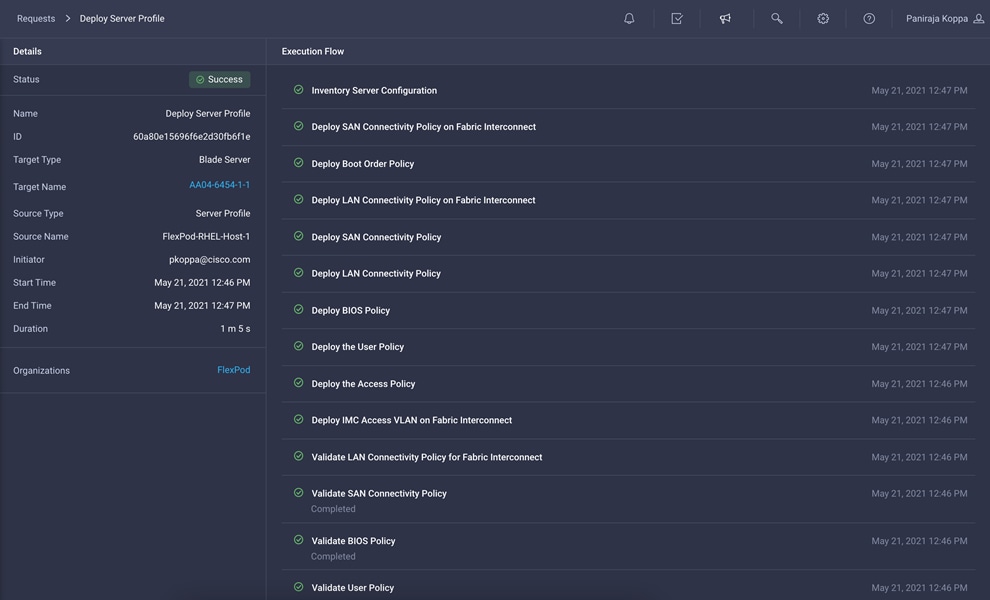
After few minutes, you should see that the server profile is deployed.
Verify LAN, SAN, and IQN addresses
After the server profile has been deployed successfully, gather the information about the MAC addresses assigned to vNICs and the WWPN addresses assigned to vHBAs by following these steps:
1. Log in to Cisco Intersight portal.
2. Go to CONFIGURE > Profiles and select the server profile you just deployed.
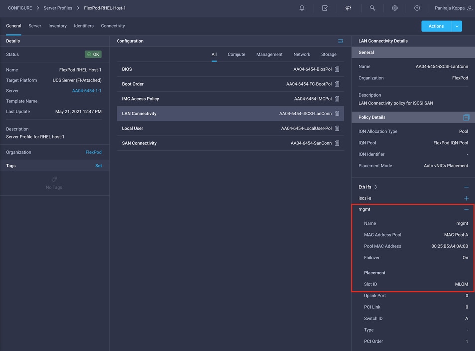
3. In the main window, click LAN Connectivity.
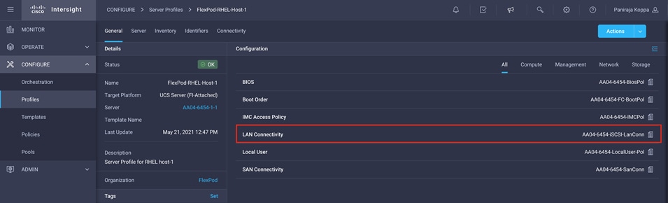
4. In the pane on the right, each NIC is listed along with the assigned MAC address. This information is useful for identifying the management vNICs for installing Red Hat Enterprise Linux on the server and setting up the initial management access.
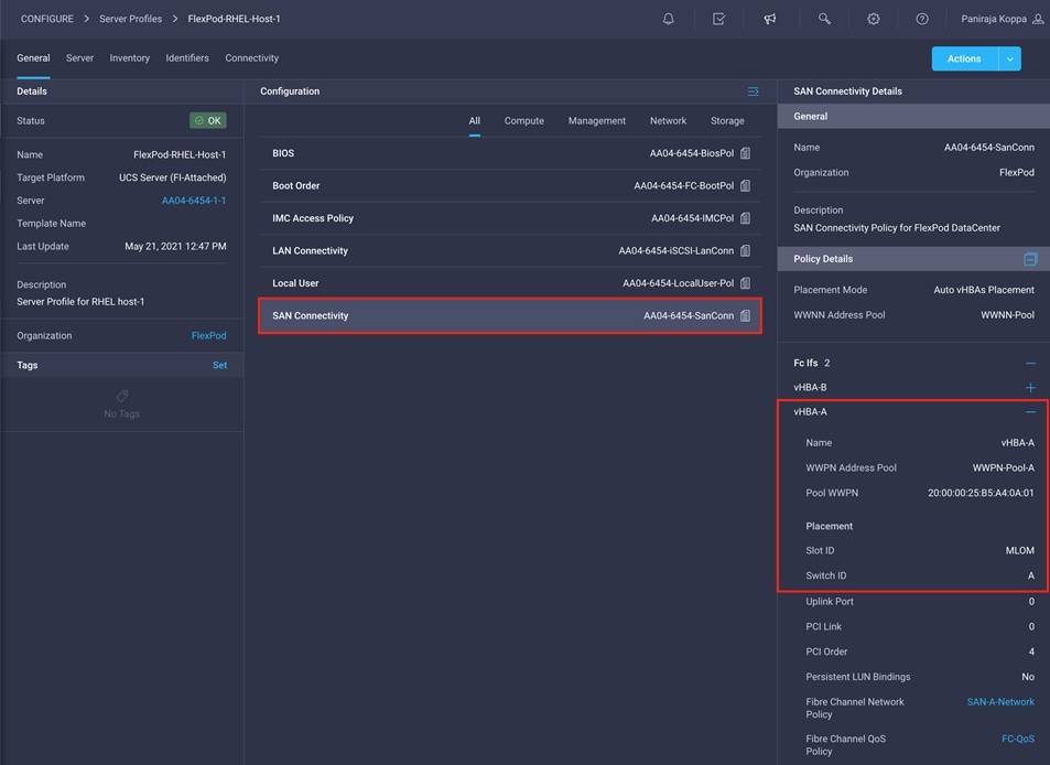
5. Click SAN Connectivity to gather the information about the WWPN address assigned to vHBA-A and vHBA-B. This information is required to set up Cisco MDS zoning and to map boot LUNs on NetApp.
6. Choose CONFIGURE > Pools and select the IQN address pool you created (for example, FlexPod-IQN-Pool).
7. Navigate to the Usage tab and note the IQN address for the server profile FlexPod-RHEL-Host-1.
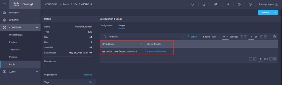
Table 5 lists the MAC and IQNaddresses for the server profile FlexPod-RHEL-Host-1 used for iSCSI SAN
Table 5. MAC and IQN addresses for the server profile for iSCSI SAN
| Interface |
MAC address |
IQN address |
| mgmt |
00:25:B5:A4:0A:0B |
|
| iscsi-a |
00:25:B5:A4:0A:0A |
iqn.2010-11.com.flexpod:ucs-host:5 |
| iscsi-b |
00:25:B5:A4:0B:04 |
Table 6 lists the MAC and WWPN addresses for the server profile used for iSCSI SAN
Table 6. MAC and WWPN addresses for the server profile for FC SAN
| Interface |
MAC address |
WWPN address |
| mgmt |
00:25:B5:A4:0A:0B |
|
| vHBA-A |
|
20:00:00:25:B5:A4:0A:01 |
| vHBA-B |
|
20:00:00:25:B5:A4:0B:01 |
Configure Cisco MDS zoning
The Cisco MDS configuration for zoning is no different than the typical Cisco MDS configuration in FlexPod. Refer to the Cisco MDS configuration for zoning in the FlexPod deployment guide: https://www.cisco.com/c/en/us/td/docs/unified_computing/ucs/UCS_CVDs/fp_dc_ontap_97_ucs_4_vmw_vs_67_U3.html#_Toc46246585.
The NetApp LUN configuration is no different than the typical NetApp storage configuration in FlexPod. Refer to the NetApp configuration for LUN creation and LUN and igroup mapping in the FlexPod deployment guide:
Create a template and deploy additional server profiles
You can create a template from a server profile that you can use to derive and deploy multiple server profiles. Any property modification made in the template synchronizes with all the derived profiles. You can deploy these modified profiles individually. This feature facilitates quick and easy configuration because multiple profiles can be created and edited simultaneously.
When a server profile deployment is complete, you can deploy additional server profiles simply by cloning an existing server profile.
To create additional server profiles by cloning, follow these steps:
1. Go to Profile and click the Options icon (…). Choose Create Template.
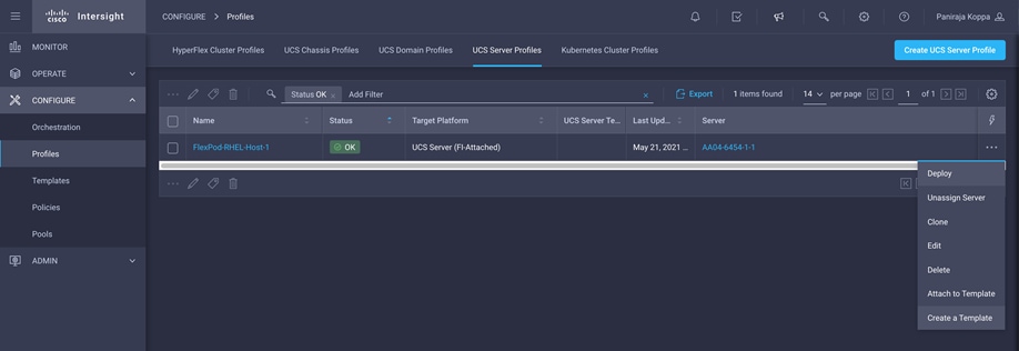
2. Provide a name for the template (for example, FlexPod-RHEL-Host-Template).
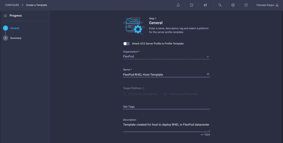
3. Click Next and click Close.
4. Navigate to CONFIGURE > Templates. Select the template you created and choose Derive.
5. Choose the server to assign and click Next.
6. Choose a name for the profile prefix (for example, FlexPod-RHEL-Host) and a start index (for example, 2).
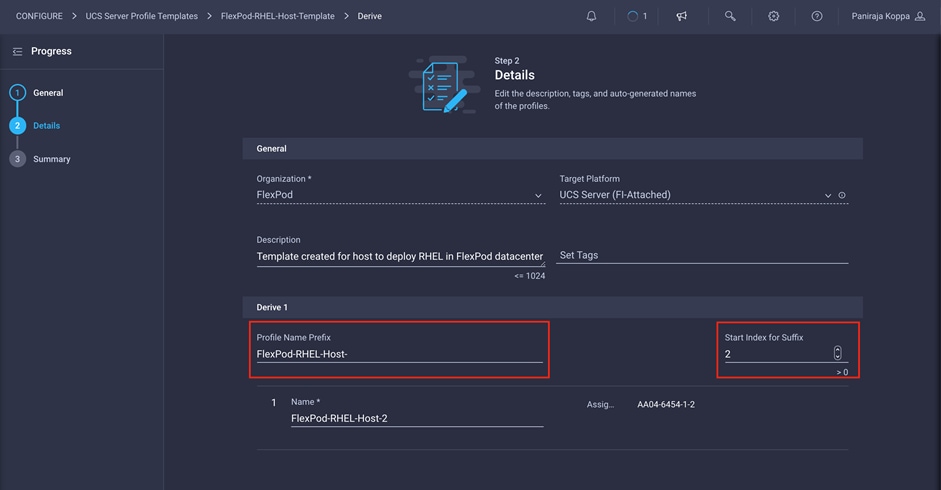
7. Click Next and click Derive.
8. Repeat steps 4 through 7 for all the servers.
Install Red Hat Enterprise Linux 8 on a server profile
After a server profile has been deployed successfully, install an operating system by following these steps:
1. Go to OPERATE > Servers and click the server. Click Actions and choose Launch vKVM.
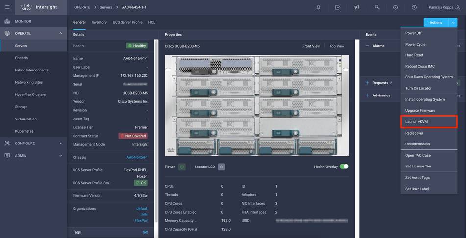
2. On the new KVM tab on the browser, click Virtual Media and choose Activate Virtual Devices.
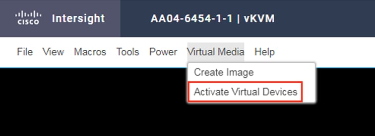
3. Click Virtual Media again and choose Map CD/DVD.
4. Browse to RHEL8 Update 3 ISO and click Map Drive.
5. In the Cisco Intersight portal, select the server and choose Power Cycle from the Actions menu.
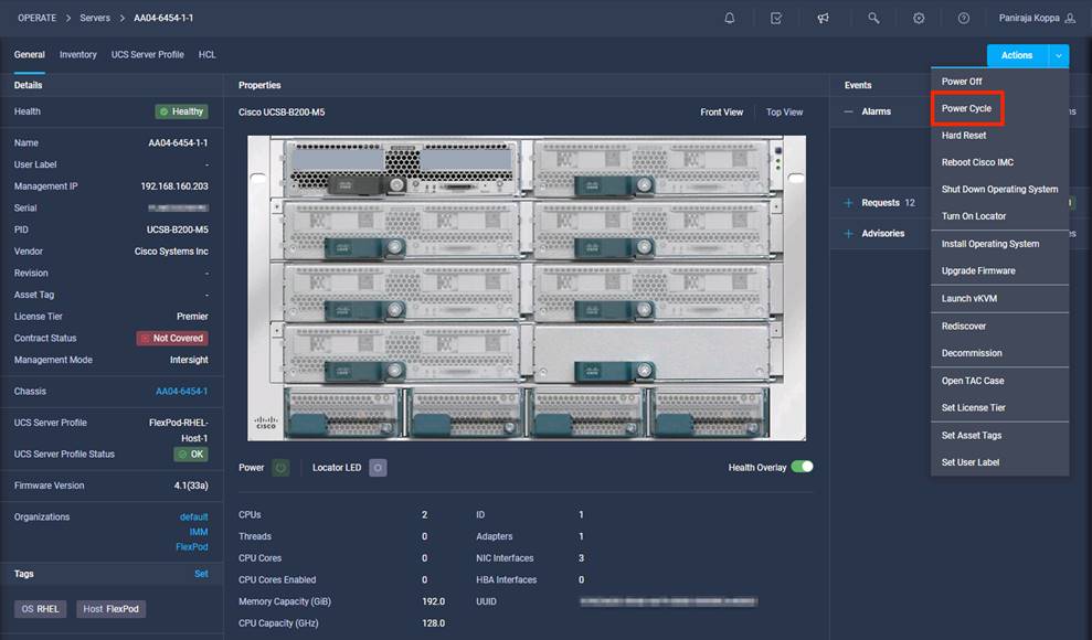
6. Select Set One Time Boot Device and choose ISO (the label previously created for the CD/DVD) from the Boot Device drop-down menu.
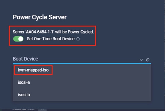
7. Click Power Cycle.
8. From the Actions tab, choose Launch vKVM. In the KVM window, you should see the server being power cycled.
If you are performing iSCSI boot, then you should see that the server has successfully discovered the boot LUN over all four paths.
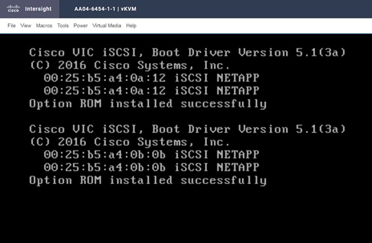
If you are performing Fibre Channel boot, then all Fibre Channel paths should be visible.
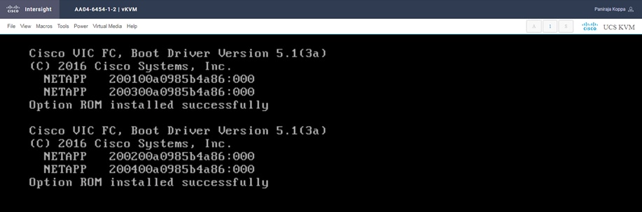
Note: This boot firmware execution screen is visible only in the Legacy BIOS mode. If you select uEFI while configuring boot-order policy, these screens will be different.
9. If you press F6 and enter boot options, you should see all the boot options (Only in Legacy BIOS mode)
For iSCSI, you should see options similar to those shown here:

For Fibre Channel boot, you should see options similar to those shown here:
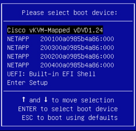
10. If you are installing RHEL 8 on a Fibre Channel boot disk, you do not need to pass any parameters to the Anaconda installer program. You can directly choose Install Red Hat Enterprise Linux 8.3 to start the installation.
If you are installing RHEL 8 on an iSCSI boot disk, then you need to append the ip=ibft parameter. To connect to an iSCSI target automatically, you must activate a network device to access the target. The recommended way to activate a network is to use the ip=ibft boot option.
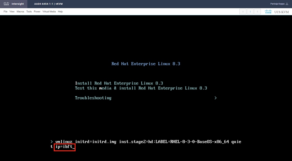
11. Continue with the OS installation wizard. When you click Installation Destination, you should see the boot LUN under Specialized and Network Disks.
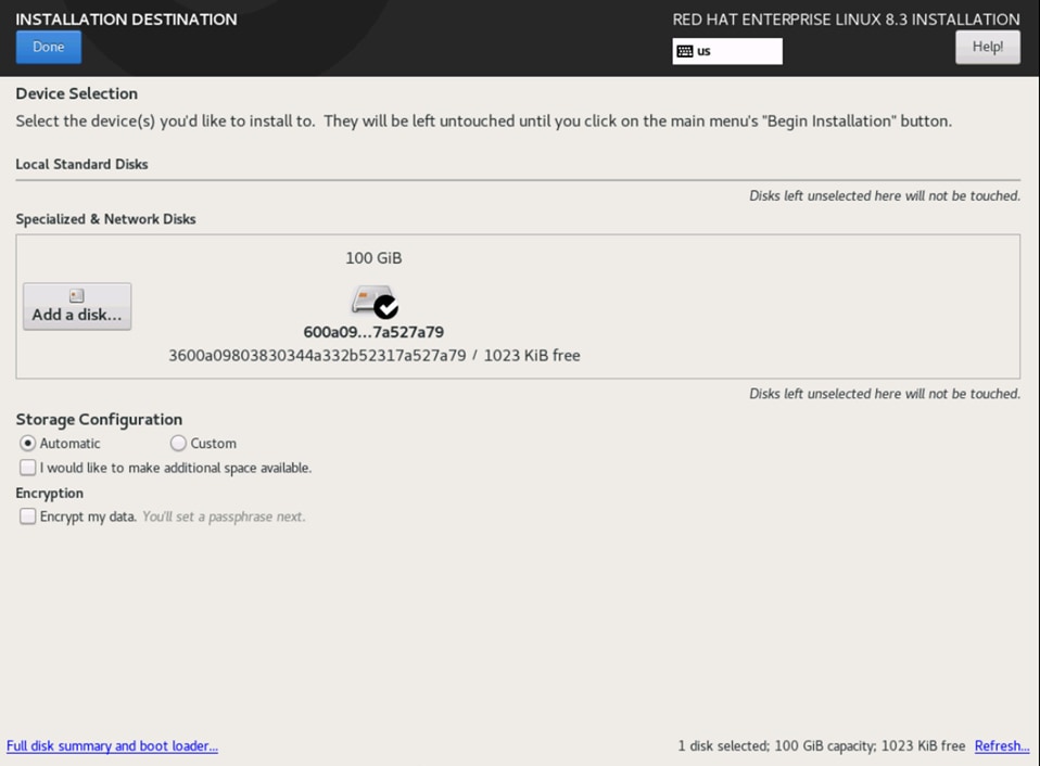
12. To confirm that the multipath driver is loaded, click “Add a disk” and select Multipath Devices. You should see four disks listed.
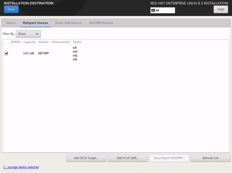
13. Complete the OS installation on the SAN LUN. For more information about the installation process, refer to the Red Hat Linux installation document available at https://access.redhat.com/documentation/en-US/Red_Hat_Enterprise_Linux/8/.
Install network and storage drivers
Make sure that the drivers are always updated and compatible as described at the Cisco UCS Hardware and Software Compatibility portal.
Here, two important drivers need to be upgraded:
● fnic: For Fibre Channel storage
● enic: For Ethernet
1. Open the terminal to see the versions of the drivers currently installed.
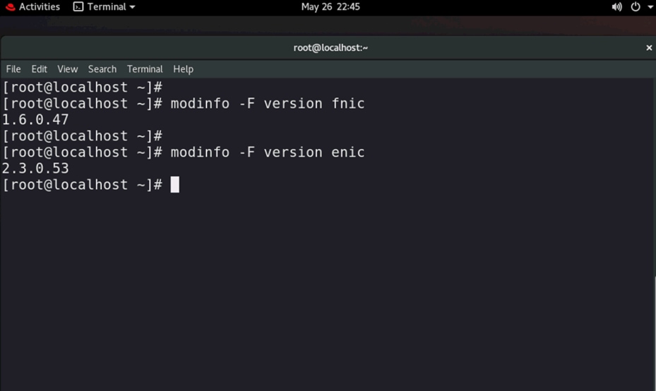
2. Go to the Cisco UCS Hardware and Software Compatibility portal at https://ucshcltool.cloudapps.cisco.com/public/. Enter the server model you are using and the operating system you want to install.
Select the firmware version and adapter model and see what the recommended driver version is.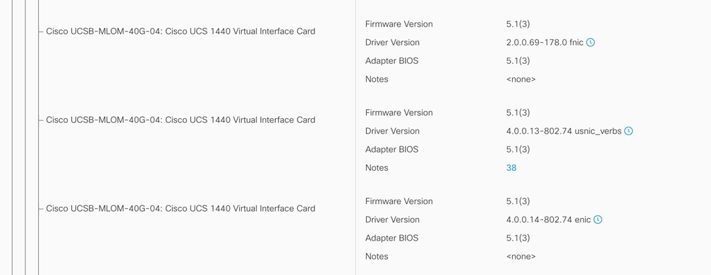
3. If your systems does not have recommended fnic version (2.0.0.69-178.0) or the recommended enic version (4.0.0.14-802.74), follow the steps below to upgrade the drivers.
4. Download the driver ISO file.
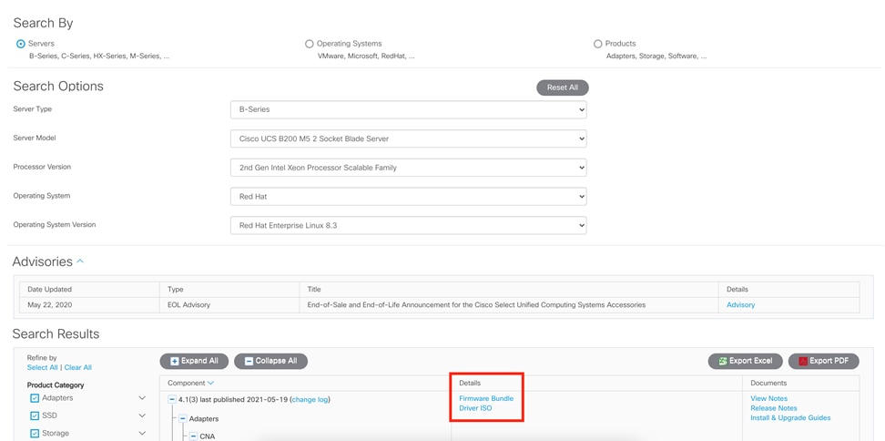
5. Mount the ISO file as a vKVM-mapped DVD. Navigate to the kernel module (KMOD) Red Hat Package Manager (RPM) location and install the driver.
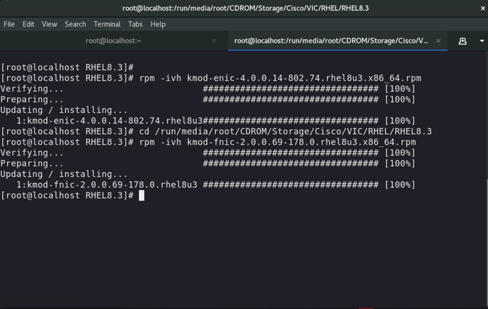
6. Verify that the fnic and enic drivers are updated to the correct versions after you have installed the KMOD RPMs.