Cisco Multi-Cloud Networking Solution With Google Cloud White Paper
Available Languages
Bias-Free Language
The documentation set for this product strives to use bias-free language. For the purposes of this documentation set, bias-free is defined as language that does not imply discrimination based on age, disability, gender, racial identity, ethnic identity, sexual orientation, socioeconomic status, and intersectionality. Exceptions may be present in the documentation due to language that is hardcoded in the user interfaces of the product software, language used based on RFP documentation, or language that is used by a referenced third-party product. Learn more about how Cisco is using Inclusive Language.
Cisco Multi-Cloud Networking Solution overview
In today’s world, enterprises are undergoing increasing pressure to innovate rapidly, to keep up with competition and to increase IT agility to meet customer demands. To achieve these goals, businesses are choosing different infrastructure environments for deploying different types of applications. Some applications may be best suited to be hosted on-premises, whereas other applications may be best suited to be hosted in a public cloud, and yet others may benefit from hybrid deployments. In fact, hybrid cloud is becoming the new normal for many businesses.
However, in a hybrid-cloud environment it is becoming more and more challenging to maintain a homogeneous enterprise operational model, comply with corporate security policies, and gain visibility across hybrid environments. The Cisco Multi-Cloud Networking solution is a comprehensive solution that provides simplified operations, consistent policy management, and visibility across multiple on-premises data centers and public clouds or hybrid-cloud environments. It allows customers running Cisco ACI in their on-premises data centers to extend their Cisco ACI policies to public clouds.
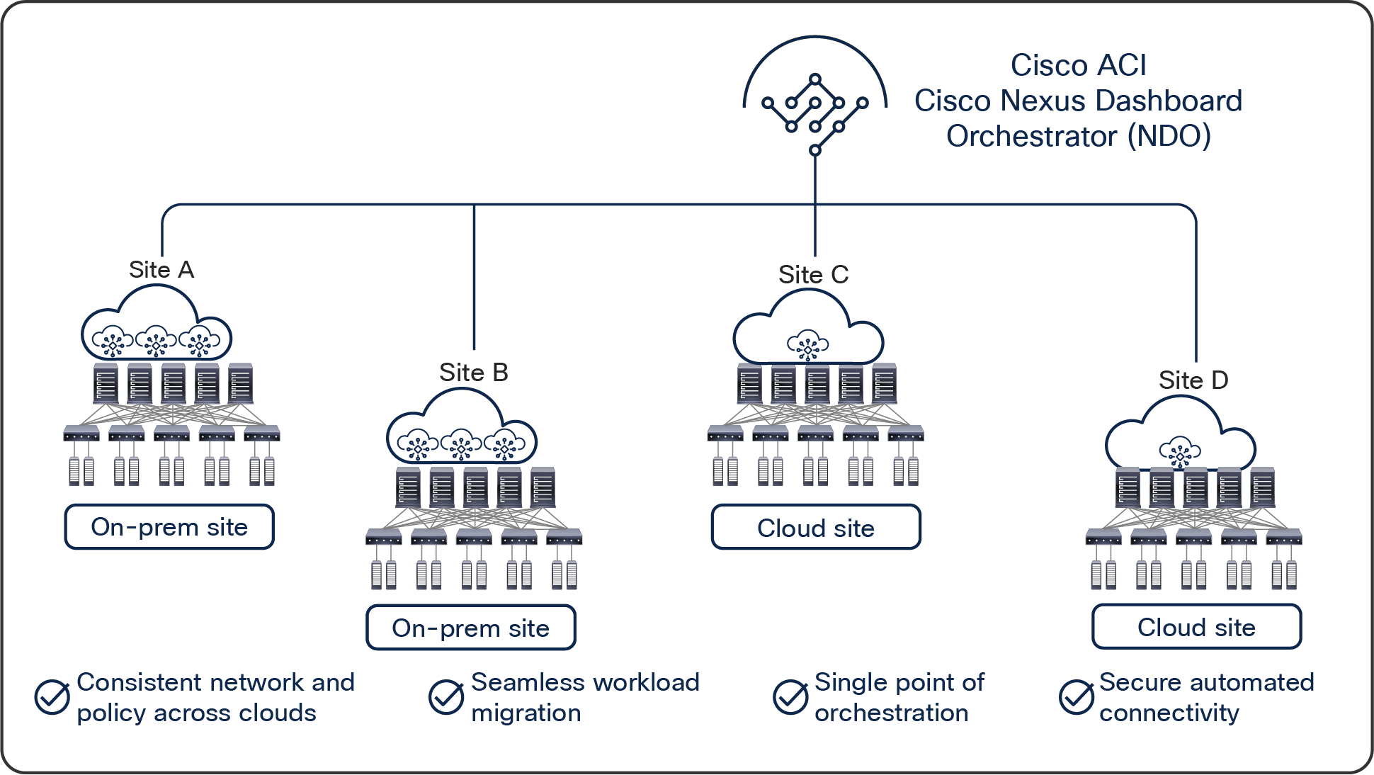
In an on-premises Cisco ACI data center, a Cisco Application Policy Infrastructure Controller (APIC) is the single point of policy configuration and management for all the Cisco ACI switches deployed in the data center. When there is a need to seamlessly interconnect multiple Cisco ACI–powered data centers and selectively extend Cisco ACI constructs and policies across sites, Cisco Nexus Dashboard Orchestrator (NDO) (formerly known as Cisco Multi-Site Orchestrator [MSO]) enters the scene. NDO is a software solution that represents a single point of policy orchestration and visibility across multiple geographically dispersed ACI sites.
With the new Cisco Multi-Cloud Networking capabilities delivered in Cisco Cloud APIC* Release 4.1 with AWS, Release 4.2 with Microsoft Azure, and Release 25.0(3) with Google Cloud Platform (GCP), NDO can manage policies across multiple on-premises Cisco ACI data centers as well as public clouds. The policies configured from NDO can be pushed to different on-premises Cisco ACI sites and cloud sites. Cisco APIC controllers running on premises receive this policy from NDO, then render and enforce it locally. When extending Cisco ACI to the public cloud, a similar model applies. But there is a twist. Public cloud vendors do not speak Cisco ACI natively. Things such as endpoint groups (EPGs) or contracts are not familiar concepts there. NDO policies therefore need to be translated into cloud-native policy constructs. For example, contracts between Cisco ACI EPGs need to be translated into firewall ingress and egress rules on GCP first, then applied to GCP virtual machines’ interfaces. This policy translation and programming of the cloud environment is performed using a new component of the Cisco Multi-Cloud Networking solution called Cisco Cloud Network Controller (formerly known as Cisco Cloud Application Policy Infrastructure Controller: Cisco Cloud APIC or Cloud APIC).
*Starting from Release 25.0(5), Cisco Cloud APIC is renamed as Cisco Cloud Network Controller. This document uses Cisco Cloud Network Controller mainly though this document still uses “Cloud APIC” in the sentences that indicate releases prior to 25.0(5).
Cisco Cloud Network Controller runs natively on supported public clouds [1]to provide automated connectivity, policy translation, and enhanced visibility of workloads in the public cloud. Cisco Cloud Network Controller translates all the policies received from NDO and programs them into cloud-native constructs such as VPCs (Virtual Private Clouds), subnets, firewall ingress and egress rules, etc.
This new solution brings a suite of capabilities to extend your on-premises data center into true hybrid-cloud architectures, helping drive policy and operational consistency regardless of where your applications reside. It provides a single point of policy orchestration across hybrid environments, operational consistency, and visibility across different types of clouds such as AWS, Microsoft Azure, and GCP.
High-level architecture of Cisco Multi-Cloud Networking solution
Figure 1 shows the overall high-level architecture of Cisco Multi-Cloud Networking solution with Cisco Nexus Dashboard Orchestrator acting as a central policy controller, managing policies across multiple on-premises Cisco ACI data centers as well as hybrid environments, with each cloud site being abstracted by its own Cisco Cloud Network Controller. The rest of this white paper discusses the architecture, benefits, use cases, and deployment of Cisco Multi-Cloud Networking solution on GCP.
Challenges in hybrid-cloud environments
As the adoption of hybrid cloud strategies grows, the industry is demanding consistent policy, security, and visibility everywhere with a simplified and consistent operating model. At the same time, the total cost of the solution must be kept under control to benefit from the hybrid-cloud advantages.
The main challenges in building and operating a hybrid-cloud environment are:
● Automating the creation of secure interconnects between on-premises and public clouds
● Dealing with the diverse and disjoint capabilities across on-premises private cloud and public cloud
● Multiple panes of glass to manage, monitor, and operate hybrid cloud instances
● Inconsistent security segmentation capabilities between on-premises and public clouds
● Facing the learning curve associated with operating public cloud environment
Cisco ACI has delivered on the software-defined networking (SDN) promise of intent-based network configuration and automation and further simplified operations by delivering control and visibility based on network policies that closely mimic your applications. The next phase of Cisco ACI must now address extending this policy-driven automation to hybrid environments. The Cisco Cloud Multi-Cloud Networking solution offers a coherent hybrid-cloud strategy delivering on the key pillars of automation, security, and simplicity.
High-level architecture of Cisco Multi-Cloud Networking solution with Google Cloud
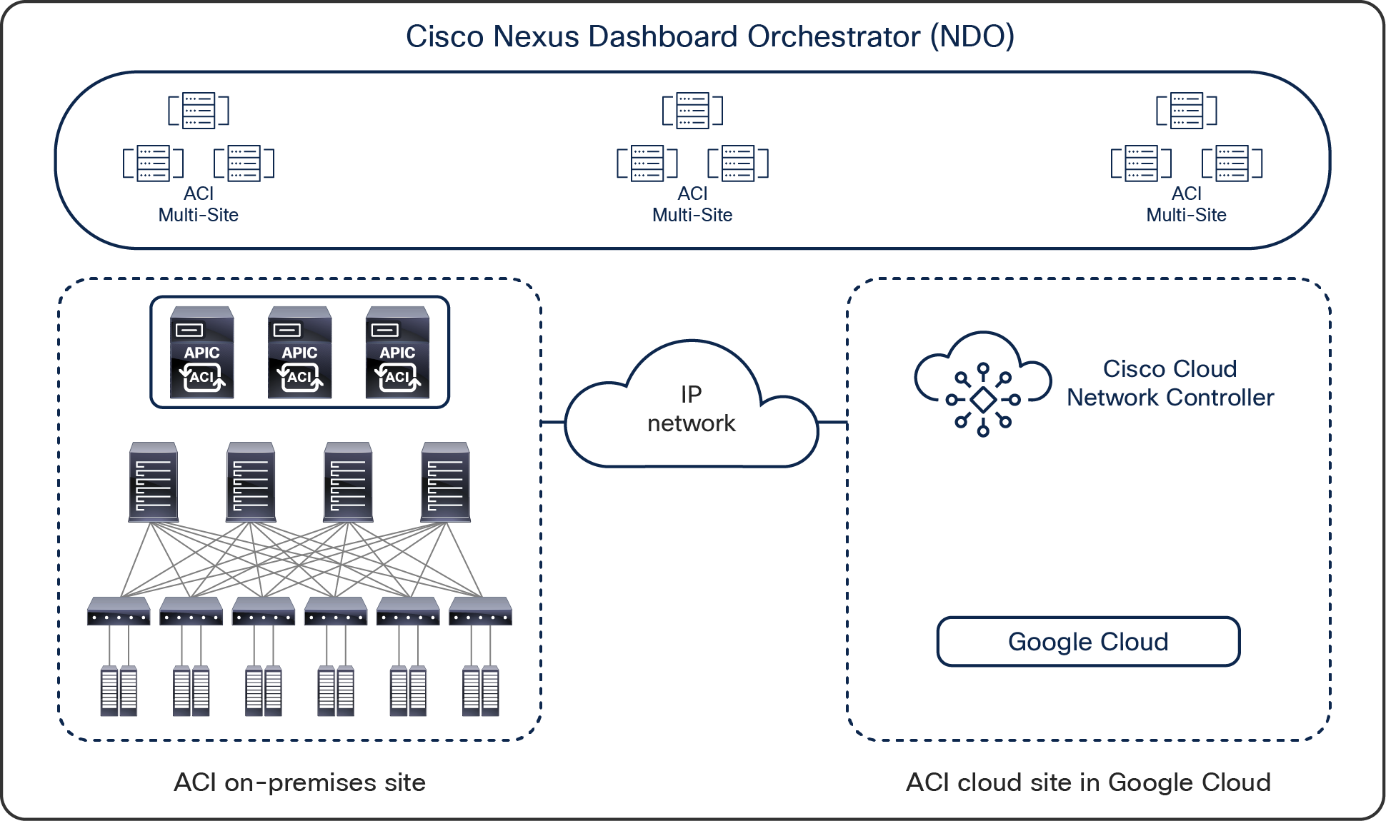
As briefly explained above and further depicted in Figure 2, an instance of NDO orchestrates multiple independent sites using a consistent policy model and provides a single pane of glass for centralized management and visibility. The sites can be on-premises Cisco ACI fabric sites with their own site-local APIC clusters, or cloud sites in GCP with Cisco Cloud Network Controller to manage the cloud site. Just as with a normal Cisco ACI Multi-Site architecture, all the sites are interconnected through a “plain” IP network. There is no need for IP multicast or Dynamic Host Configuration Protocol (DHCP) relay here. Just take care of providing IP connectivity, and NDO will be responsible for setting up the intersite overlay connectivity.
For more details on the Cisco ACI Multi-Site solution, refer to the following white paper:
Cisco Multi-Cloud Networking solution with GCP architecture
The key building blocks of the Cisco Multi-Cloud Networking solution architecture include the following:
● Cisco Nexus Dashboard Orchestrator (NDO). NDO release 4.0(1) or later is required for an ACI cloud site in GCP.
● On-premises Cisco ACI site running Cisco ACI Release 4.1 or later (ACI Release 4.2 or later is required for Azure cloud site support). The on-premises site needs to be equipped with at least one second-generation spine model (EX, FX, C, or GX) for intersite connectivity.
Note: Starting with ACI Release 4.2, an on-premises ACI site is optional in the Cisco Multi-Cloud Networking solution architecture. The architecture also supports designs that have only cloud sites.
● For the focus of this white paper, the public cloud in discussion is GCP. Cisco Cloud Network Controller Release 25.0(5) or later for GCP site is required for intersite orchestration.
● Intersite connectivity. This includes the connectivity between on-premises and cloud sites, as well as the connectivity between cloud sites.
● The network policy mapping between the Cisco ACI policy model and the corresponding cloud-native policy model. For the focus of this white paper, an GCP-native policy model is used.
Cisco Nexus Dashboard Orchestrator (NDO)
In a Cisco ACI Multi-Site architecture, the Cisco Nexus Dashboard Orchestrator (NDO) is the single pane of glass for management of all the interconnected sites. It is a centralized place to define all the inter-site policies that can then be published to the individual Cisco ACI sites where the site-local APICs render them on the physical switches that build those fabrics.
With the Cisco Multi-Cloud Networking solution, NDO’s orchestration functions expand to the cloud sites. It is responsible for site registration of both on-premises Cisco ACI data center sites and the cloud sites. It automates the creation of overlay connectivity between all the sites (on-premises and cloud). Continuing to be the central orchestrator of intersite policies, NDO now can, not only publish policies to on-premises Cisco ACI data center sites, but also push the same policies to cloud sites in GCP. It is also capable of instrumenting the policy deployment among different sites by selectively distributing the policies to only the relevant sites. For instance, NDO can deploy the web front tier of an application into the cloud site in GCP while keeping its compute and database tiers in the on-premises site. Through the NDO interface, network administrators can also regulate the communication flow between the on-premises site and GCP as required by applications.
Cisco Cloud Network Controller on GCP
Cisco Cloud Network Controller is an important new solution component introduced in the architecture of the Cisco Multi Cloud Networking solution. It plays the equivalent of APIC for a cloud site. Like APIC for on-premises Cisco ACI sites, Cloud Network Controller manages network policies for the cloud site that it is running on, by using the Cisco ACI network policy model to describe the policy intent. Cisco Cloud Network Controller is a software-only solution that is deployed using cloud-native instruments through cloud marketplaces. Network and security policies can be locally defined on the Cloud Network Controller for the cloud site, or globally defined on NDO and then distributed to Cisco Cloud Network Controller. While the on-premises APIC renders the intended policies onto the Cisco ACI switches of the site, Cloud Network Controller renders the policies onto the GCP cloud network infrastructure. It accomplishes this task by translating the Cisco ACI network policies to the GCP-native network policies and uses the GCP-native policy API to automate the provisioning of the needed GCP-native cloud resources, such as Virtual Private Clouds (VPCs), Cloud Routers, firewall rules, etc. In a nutshell, the key functionalities of Cisco Cloud Network Controller include the following:
● Provides a north-bound REST interface to configure cloud deployments
● Accepts Cisco ACI Policy Model and other cloud-specific policies directly or from NDO
● Performs endpoint discovery in the cloud site
● Performs Cisco ACI Cloud Policy translation
● Configures the Cloud Router’s control plane
● Configures the data-path between a Cisco ACI fabric and the cloud site
Cisco Cloud Network Controller is a microservices-based software deployment of the APIC. Cisco Cloud Network Controller on GCP is deployed and runs as an GCP virtual machine. Virtual machines for Cisco Cloud Network Controller are available at GCP Marketplace, and use Bring Your Own License (BYOL) model for licensing.
As Cisco APIC for an on-premises ACI fabric, Cisco Cloud Network Controller contains only policies and is not in the data forwarding path. Any downtime of Cloud Network Controller will not impact network forwarding functionality or performance in the cloud site. Upon a failure in Cloud Network Controller, it can always restore to the previous configuration. Therefore, for simplicity and cost effectiveness, Cisco Cloud Network Controller is deployed as a single GCP virtual machine.
Key benefits of using Cisco Multi-Cloud Networking solution
The Cisco Multi-Cloud Networking solution provides the following key benefits:
Automation of on-premises to cloud interconnect
Cisco Multi-Cloud Networking solution with GCP automates the configuration of end-to-end connectivity between an on-premises Cisco ACI fabric and GCP. This connectivity can take place using IPsec VPN. Cisco Cloud Network Controller deploys cloud routers (a pair of Cisco Catalyst 8000Vs, or Google Cloud Routers and Google Cloud VPN Gateway) in GCP and programs them to form an IPsec tunnel to the IPsec terminator that is installed on premises. Once the IPsec tunnel is up, NDO configures the BGP EVPN control plane as well as VXLAN tunnel between the on-premises Cisco ACI spines and the Cisco Catalyst 8000Vs deployed on GCP. This end-to-end automation makes hybrid-cloud connectivity seamless, reducing the configuration time and risk of errors and accelerating the pace of deployment and rate of change. Later in the document, more technical details are provided regarding this automated intersite connectivity.
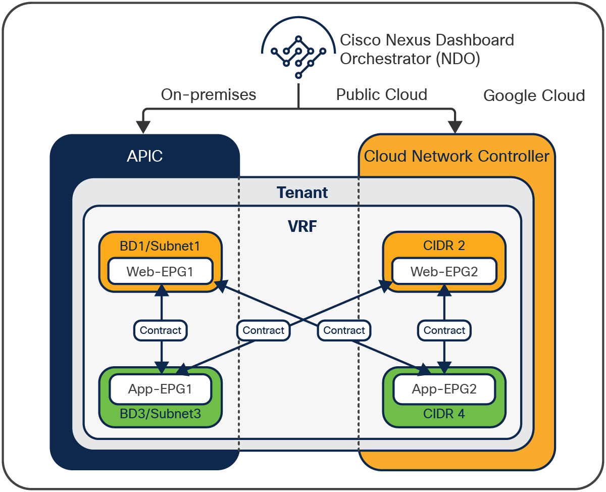
Universal policy model
The logical network constructs of the Cisco ACI network policy model consist of tenants, bridge domains (BDs), bridge-domain subnets, endpoint groups (EPGs), and contracts. GCP uses slightly different constructs: projects, Virtual Private Clouds (VPCs), subnets, and firewall ingress and egress rules.
As shown in Figure 3, Cisco ACI classifies endpoints into EPGs and uses contracts to enforce communication policies between these EPGs.
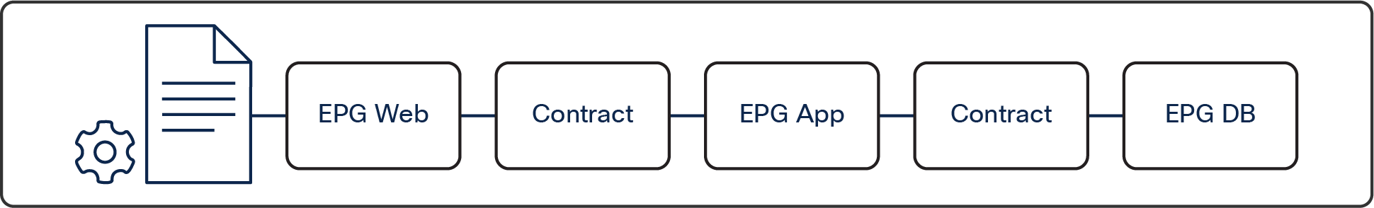
Cisco ACI EPG-based network model
GCP doesn’t have equivalent corresponding component for an EPG. GCP uses targets and filters to define firewall egress and ingress rules for security policy enforcement. Targets and filters are based on network tags, service accounts, and IP addresses. Figure 4 gives one example of GCP security enforcement using firewall rules.
For more details on firewall rules, refer to the GCP document: https://cloud.google.com/vpc/docs/firewalls
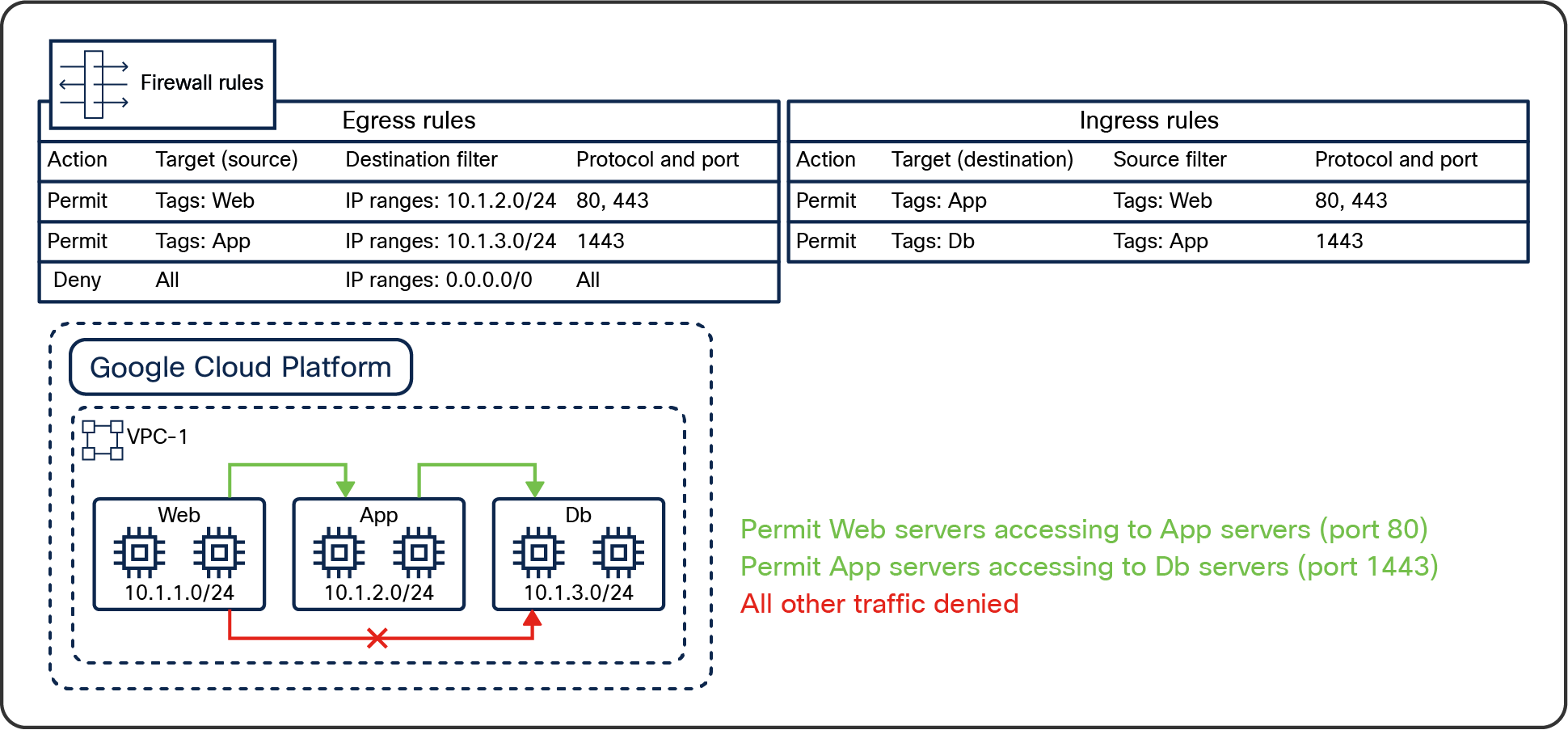
GCP firewall rules
Granular and accurate mapping between these two network policy models is crucial to ensure the correct deployment of network policies across Cisco ACI and GCP. Figures 5 and 6 show how Cisco Cloud Network Controller handles this policy mapping.
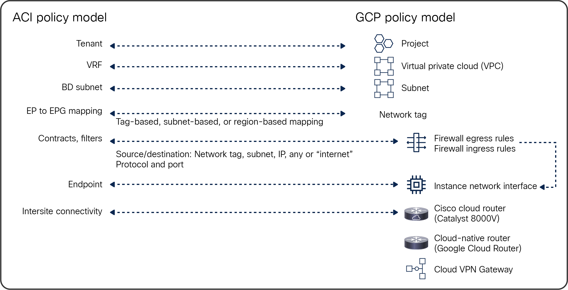
Cisco ACI Policy Model to GCP Policy Model mapping
It’s important to note that the Cisco Multi-Cloud Networking solution has two options to manage inter-VRF (inter-VPC on GCP) routing:
● The use of route-map: If a route-map is configured between VRFs, the routes are leaked to the other VRF regardless of the contract and Contract-Based Routing configuration. It is optional whether you use Cloud Network Controller to define firewall rules.
● The use of contract: If a route-map is not configured and Contract-Based Routing is enabled, a contract between EPGs in different VRFs triggers inter-VRF route leaking between the VRFs. In this case, inter-VRF routing and security policies are tightly coupled together based on contracts. You may configure a route-map in addition to a contract. In that case, the route-map drives inter-VRF route leaking (the route-map configuration wins over the contract configuration in terms of inter-VRF route leaking).
The following table summarizes the combination of the configurations.
Table 1. Combinations of the configurations
| Contract Based Routing |
Route-map |
Contract |
Inter-VRF route-leaking is driven by |
Security policy (Firewall rules) is driven by |
||
| Enabled |
Configured |
Configured |
Route-map |
Contract |
||
| Configured |
Not configured |
Route-map |
User (not contract) |
|||
| Not configured |
Configured |
Contract |
Contract |
|||
| Disabled |
Configured |
Configured |
Route-map |
Contract |
||
| Configured |
Not configured |
Route-map |
User (not contract) |
|||
| Not configured |
Configured |
N/A (It’s an invalid configuration.) |
Contract |
|||
Unified network management and operations
Cisco Nexus Dashboard Orchestrator (NDO) provides end-to-end visibility and health of all the endpoints managed by it across on-premises and public cloud environments, giving a single place to monitor the health, performance, and operational status of hybrid cloud environments. NDO being the single point of policy configuration and orchestration, this highly reduces the operational complexity of operating across hybrid environments.
Digging further: looking inside a cloud site
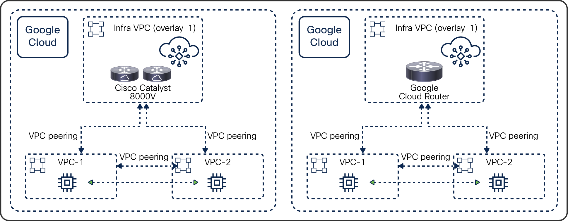
A cloud site using VPC peering
When running the Cisco Multi-Cloud Networking solution, Google Cloud VPC peerings between VPCs are deployed based on the contracts or route-maps defined on Cisco Cloud Network Controller. Figure 6 shows a logical topology using Google Cloud VPC Network Peering. It is a spoke-to-spoke topology, whereas the Cisco Multi Cloud Networking solution with AWS and Azure uses a hub-and-spoke topology.
Inside the cloud using Google Cloud VPC network peering
The infra VPC carries the logical role of the on-premises Cisco ACI infra VRF. It is where Cisco Cloud Network Controller is deployed and running. It is automatically created during the deployment of Cisco Cloud Network Controller. Cisco Cloud Network Controller then deploys cloud routers (a pair of Cisco Catalyst 8000Vs or Google Cloud Routers) in this infra VPC for providing the intersite connectivity to the on-premises Cisco ACI sites or other public-cloud sites.
A user VPC is equivalent to a tenant VRF in the Cisco ACI network policy model. Cisco Cloud Network Controller creates a user VPC when an ACI tenant VRF needs to be deployed or extended to the cloud site. Based on contracts or route-maps, Cisco Cloud Network Controller provisions VPC network peering between the VPCs to provide network connectivity within the cloud site and intersite connectivity through the infra VPC.
● Endpoint communication within the same VPC is routed locally in the VPC.
● Endpoint communication between user VPCs goes through the direct VPC peering.
● Endpoint communication between a user VPC and the on-premises site goes through the cloud routers in the infra VPC, based on the custom routes in the user VPC. The custom routes are also programmed by Cisco Cloud Network Controller.
An ACI Cloud site across multiple GCP regions
A VPC in GCP can span multiple GCP regions. Unlike AWS or Microsoft Azure, routing across regions within a VPC is automatically taken care of by GCP. Even if two endpoints are in different regions, it does not need to go through the infra VPC.
● Cross-region endpoint communication within the same VPC is routed locally in the VPC.
● Cross-region endpoint communication between user VPCs goes through the direct VPC peering.
● Endpoint communication between a user VPC and the on-premises site goes through the cloud routers in the infra VPC, based on the custom routes in the user VPC. The custom routes are also programmed by Cisco Cloud Network Controller.
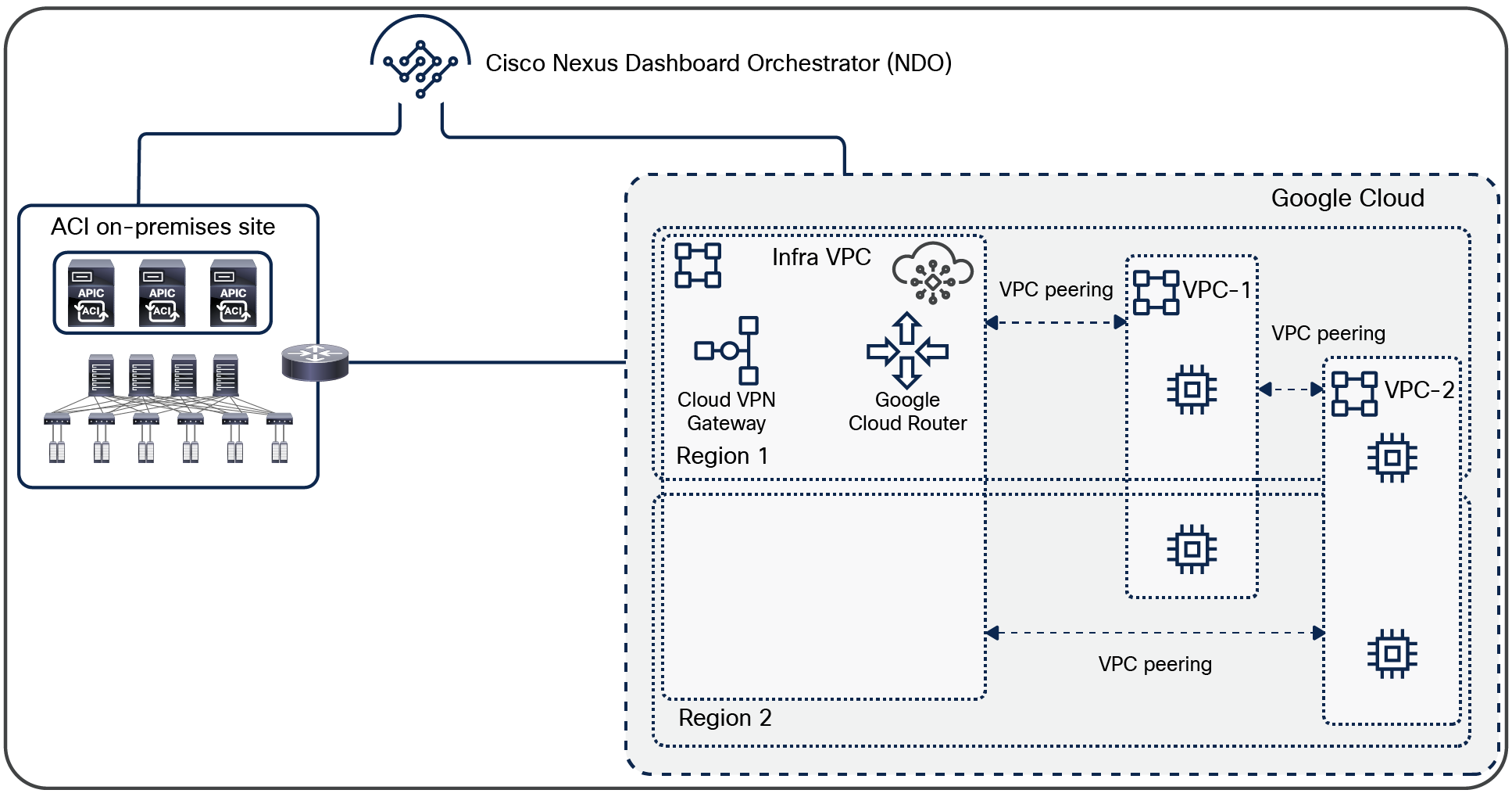
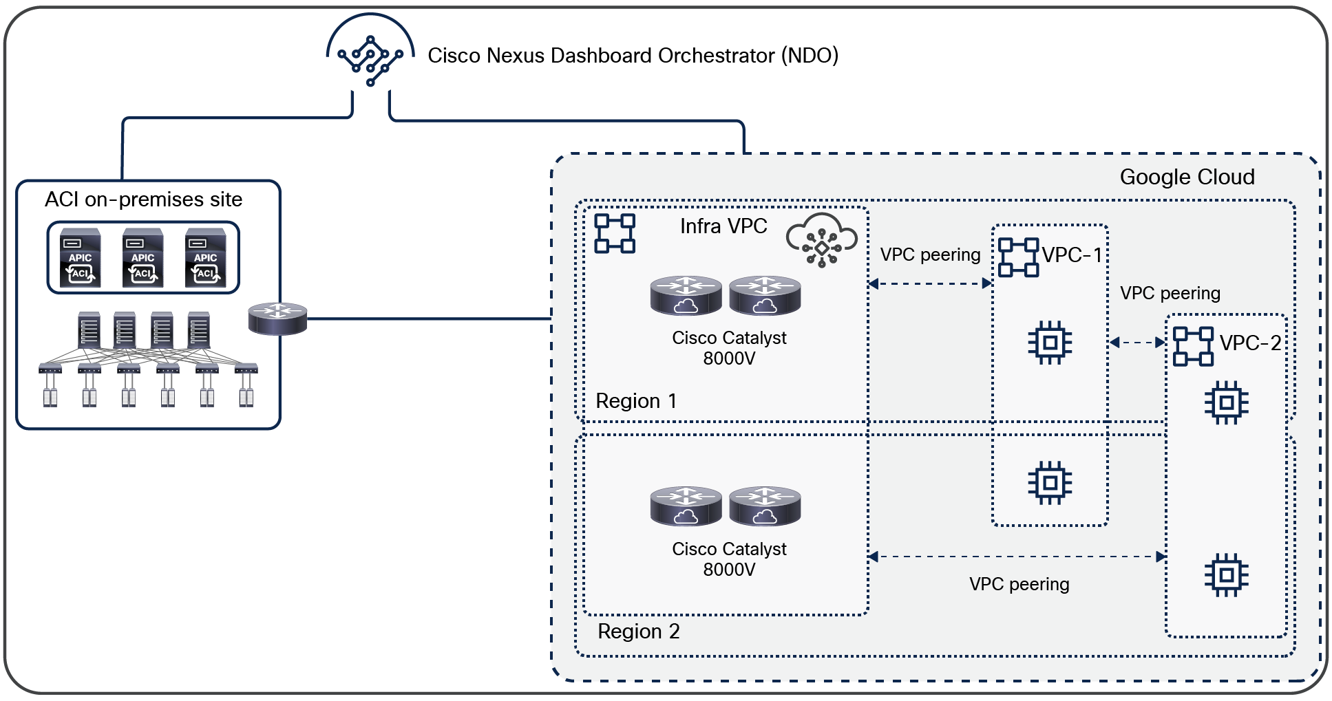
The entire cloud site is managed by the same Cisco Cloud Network Controller. One region can have both Cisco Cloud Network Controller and cloud routers (as shown in Figure 7), or cloud routers can be deployed in up to four regions for redundancy (as shown in Figure 8). Google Cloud Router and Google Cloud VPN Gateway must be in the same region and in the same VPC. In addition, Cisco Cloud Network Controller supports only one Google Cloud Router and one Google Cloud VPN Gateway per region whereas up to two Cisco Catalyst 8000Vs per region are supported.
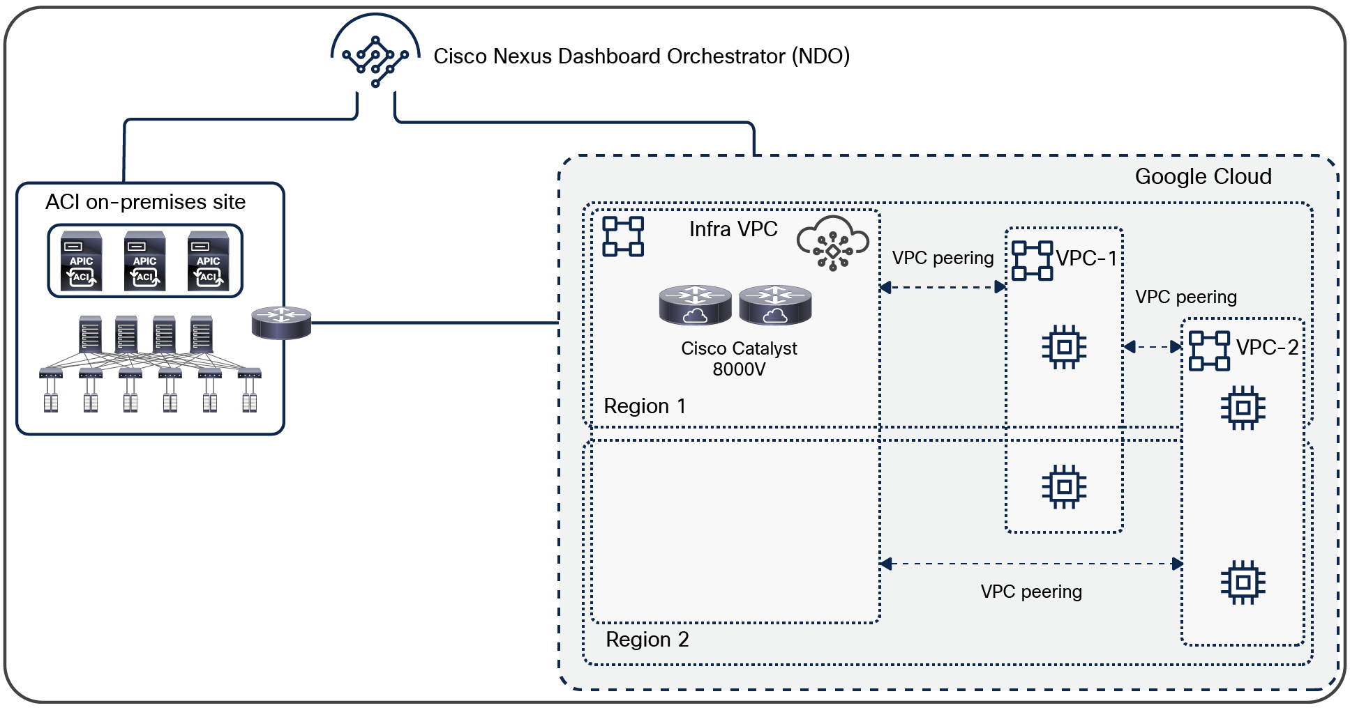
Cisco Multi-Cloud Networking solution: GCP multi-region site with cloud routers in the same region
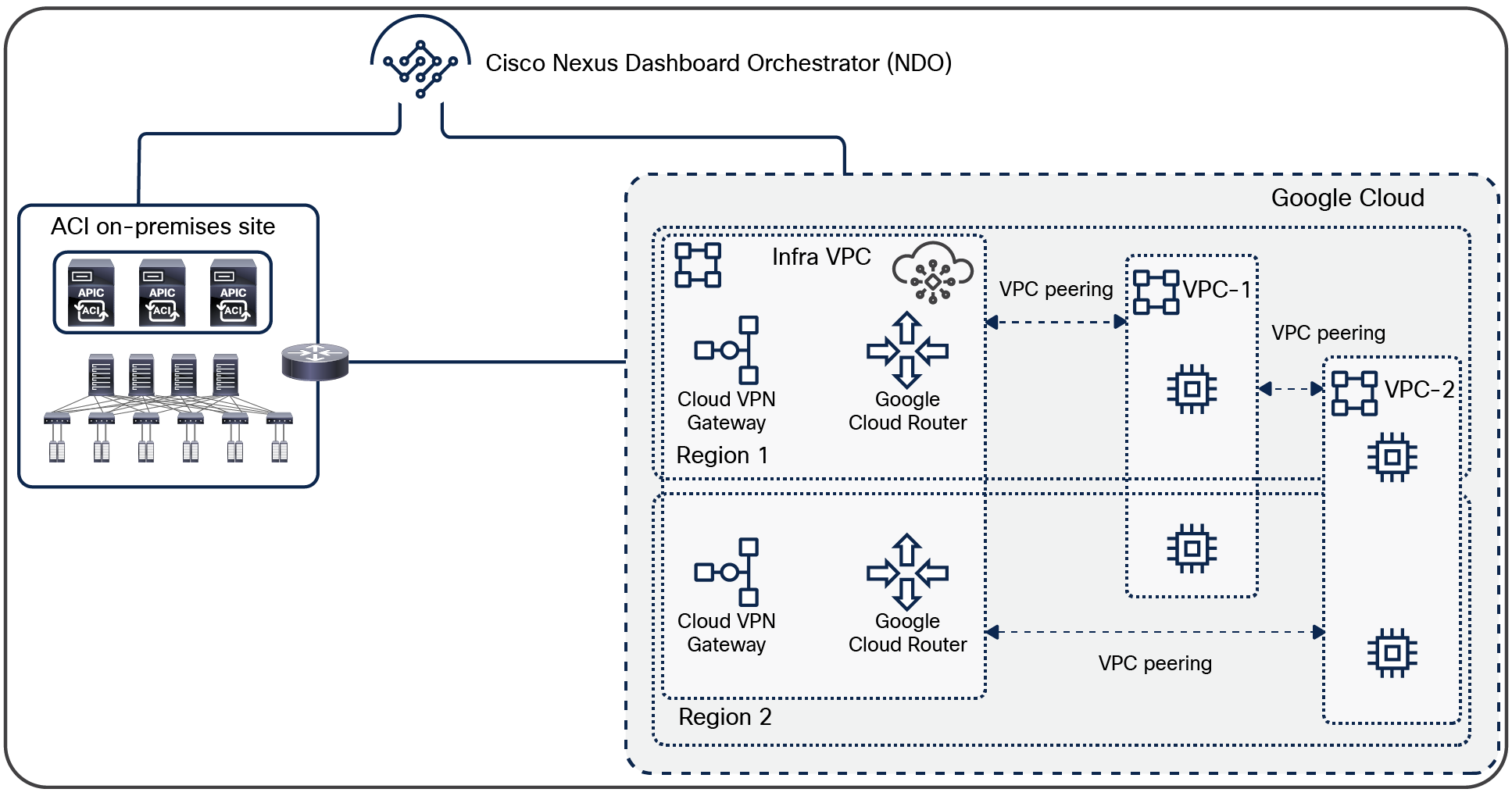
Cisco Multi-Cloud Networking solution: GCP multi-region site with cloud routers in multiple regions
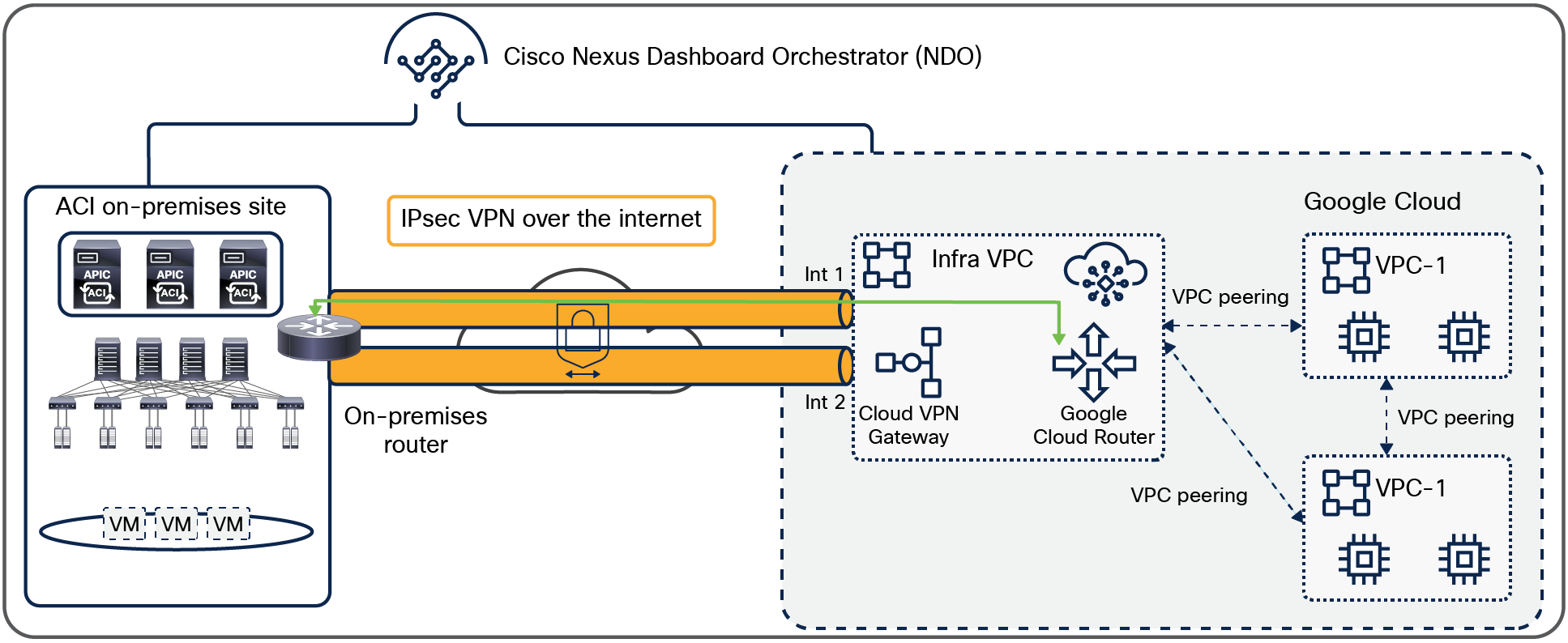
The underlay network between on-premises and cloud sites
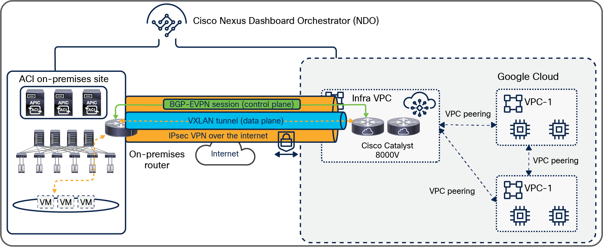
The on-premises Cisco ACI sites and the ACI cloud site in GCP are connected through an IP network that can be IPsec VPN over the internet, or through Google Cloud Interconnect [2] such as Google Cloud Dedicated Interconnect and Google Cloud Partner Interconnect. In case of IPsec VPN, the Cisco Catalyst 8000Vs or Google Cloud VPN Gateway in the Infra VPC need to be programmed to establish IPsec peering with the IPsec device located in the on-premises Cisco ACI site. NDO generates configuration templates for the IPsec device in the on-premises ACI fabric. Because the configuration templates are based on Cisco IOS XE CLI syntax, cloud administrators might need to edit it to match their router. This underlay network provides IP reachability for the overlay control plane and data plane between the two sites. This is represented in Figure 9. In the case of Google Cloud VPN Gateway, two interfaces per Cloud VPN Gateway are used for the IPsec tunnels to each on-premises router.
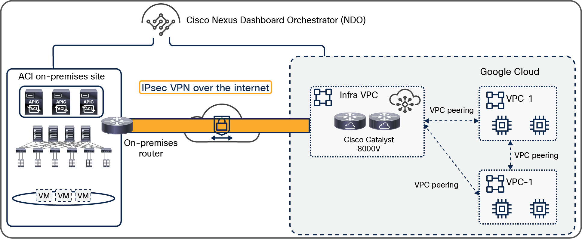
The underlay network between on-premises and cloud sites
The overlay network between on-premises and cloud sites with Cisco Catalyst 8000V
The overlay network between the on-premises and cloud sites runs BGP EVPN as its control plane and uses VXLAN encapsulation and tunneling as its data plane. The use of VXLAN is to identify the right routing domain for VRF stretch across on-premises Cisco ACI fabric and the clouds.
BGP EVPN sessions are established between the on-premises Cisco ACI spine switches and the Cisco Catalyst 8000Vs in the Infra VPC of the GCP site. Tenant host routes and prefix routes are exchanged between the two sites as BGP EVPN route type-2 (host) and type-5 (prefix). The provisioning of this overlay network connectivity is automated by NDO. Only prefix routes are exchanged by default. Host routes must be exchanged if a stretched BD exists across two or more on-premises ACI sites. This is to ensure that traffic from a cloud site goes directly to the on-premises ACI site where the destination endpoint resides; otherwise, traffic will be dropped in another on-premises ACI site that doesn’t allow transit traffic going to a different on-premises ACI site. Figure 10 zooms in on this logical/physical architecture. On-premises spines connect to an intersite network (called ISN, or IPN for an inter-pod network). That ISN layer then connects to an on-premises IPsec router that initiates IPsec tunnels to the Cisco Catalyst 8000Vs in the GCP infra VPC. MP-BGP EVPN sessions are established between the ACI spine switches and the Cisco Catalyst 8000Vs in the GCP infra VPC over the ISN network and the IPsec tunnels.
You might need to adjust the maximum transmission unit (MTU) size on ACI Control Plane MTU policy for the BGP EVPN control-plane and on your endpoints for the data plane to avoid fragmentation because of IPsec tunnels and VXLAN encapsulation overhead. Otherwise, fragmentation by devices in the network could degrade overall performance. For example, if MTU of the involved endpoints is adjusted to 1300 bytes, this would account for the additional 50 bytes from VXLAN and around 100 bytes for IPsec overhead to go over the internet where the common value of MTU is 1500 bytes. If adjusting the MTU size on your endpoints is not allowed or not preferable, you need to configure the TCP maximum segment size (MSS) adjustment on the Cisco Catalyst 8000Vs from the Cisco Cloud Network Controller.
The overlay network between on-premises and cloud sites with Cisco Catalyst 8000V
The overlay network between on-premises and cloud sites with Google Cloud Router
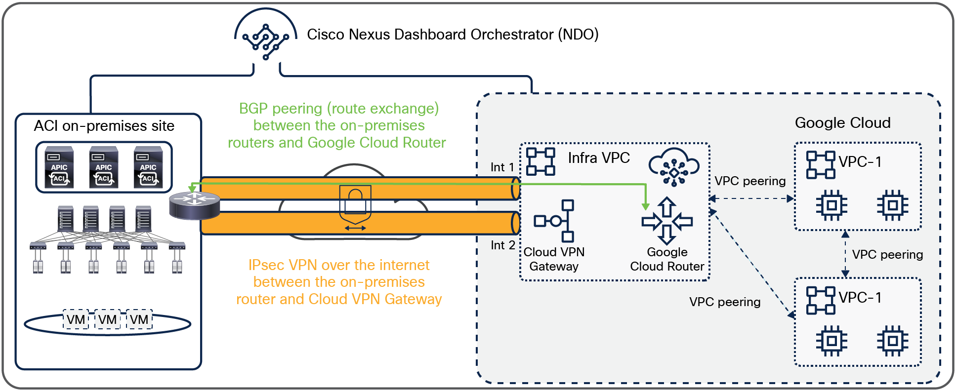
BGP neighborship is established between the routers in the on-premises site and the Google Cloud Routers in the infra VPC of the GCP site, and the routes are exchanged between them. The IP subnets are used to identify the external EPGs for the networks in the other site.
Figure 11 zooms in on this logical/physical architecture. The border leaf nodes in the on-premises ACI fabric connect to an intersite network through the on-premises router that has IPsec tunnels to the Cloud VPN gateway in the GCP infra VPC. The L3Out configuration on the border leaf nodes needs to be configured on the APIC for the on-premises ACI site, which is not configured automatically by NDO. Unlike the example with Cisco Catalyst 8000Vs above, the BGP peering and IPsec configuration on the Google Cloud Routers are NOT automated by NDO. Although NDO can manage both the on-premises ACI site and the GCP site, EPGs are not stretched across sites. Please see External site connectivity with Google Cloud Router and Cloud VPN Gateway for more details.
BGP peering between on-premises and cloud sites with Google Cloud Routers and Cloud VPN Gateway
This section explains use-case scenarios. Unless otherwise indicated, logical design examples in this section shall be examples with Cisco Catalyst 8000V, which means the overlay network between the on-premises and cloud sites runs BGP EVPN as its control plane and uses VXLAN encapsulation and tunneling as its data plane (Figure 10).
The Cisco Multi-Cloud Networking solution enables customers to achieve the following scenarios:
High availability of applications across on-premises and cloud sites
Cisco Multi-Cloud Networking solution enables customers to deploy an application in high availability by stretching it across on-premises and cloud sites. This makes it possible to have a multitier application deployed across a hybrid-cloud environment all in the same Virtual Routing and Forwarding domain (VRF). [3]
Customers having application tiers deployed on an on-premises Cisco ACI site can now add new application tiers in a cloud site interacting with the on-premises tiers using consistent policies.
Applications can fail over between the on-premises Cisco ACI site and the ACI cloud site during a disaster recovery, or the application can be deployed in an active/active mode, where both on-premises application tiers and cloud tiers are active. A Global Load Balancer can be configured to distribute traffic between the two sites.
For example, the web and application tiers of an application (two EPGs) in the same VRF running in the on-premises Cisco ACI data center. By stretching the same VRF to the cloud site, we can deploy web and application tiers in the cloud site and can be configured as an active/active between the on-premises and cloud sites. You can also deploy the on-premises web and application tiers as active, and the cloud tiers can act as standby, and can fail over to a cloud tier in case of a disaster recovery.
All of this can be achieved by using NDO as a single point of orchestration; you can configure contracts between these tiers spread across the hybrid cloud environment. Simply publishing this policy from NDO to both sites programs the end-to-end constructs required to implement the workload segmentation policy. This is shown in Figure 12.
Stretched routing domain with intersite contracts
Cloud bursting: stretch an application tier (EPG) to cloud with consistent segmentation
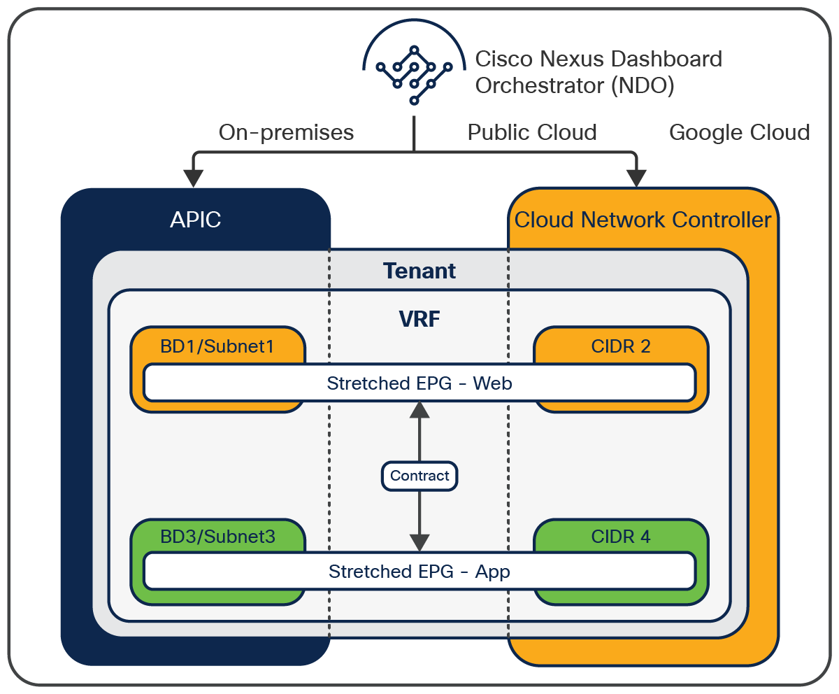
The Cisco Multi-Cloud Networking solution enables customers to stretch an application tier across the on-premises and cloud sites in GCP, which means that an ACI EPG can be stretched across the on-premises and GCP sites. This enables customers to burst a tier to GCP sites during times of peak load and access other tiers of the application on premises through secure segmentation policies. Even multiple tiers can be burst to the cloud site in GCP and still maintain the same level of policy and consistent segmentation irrespective of where the workloads are deployed.
From NDO, you can either create a new EPG that can then be stretched or import an existing EPG from the on-premises site and stretch it to GCP. This is achieved just as you would with regular Cisco ACI Multi-Site, using templates and schemas. Once that is done, configure the site-local properties that define how the EPG should classify its member endpoints.
When associating an EPG with an on-premises ACI site, you can either associate the EPG to a Virtual Machine Manager (VMM) domain, or to static ports or a VLAN/port combination to classify endpoints on premises. When the same EPG is associated with a cloud site in GCP through NDO, EPG membership classification criteria can then be based on region, tag, or IP address/subnets.
Stretching an EPG does not mean extending a broadcast domain from an on-premises site to the cloud, though; it simply means that you can create an EPG with members on premises and in the cloud, using different subnets. Once two or more endpoints are in the same EPG, communication flows freely inside that EPG.
Example: Let’s say you have an application with web and application tiers deployed in an on-premises ACI site. During a peak load time, you burst either web tier or both web and application tiers to the cloud site in GCP. You can do that seamlessly with just a couple of button clicks from NDO and stretch the tiers to GCP with the same level of security and segmentation as their on-premises workloads. Now, contracts between stretched Web EPG and on-premises EPGs or Cloud EPGs can be configured as you normally would with an on-premises ACI. Cloud-bursting doesn’t get any easier. This is shown in Figures 13.
Stretched EPGs across sites
Shared services across hybrid cloud
Shared services such as DNS, Active Directory (AD), or other authentication services deployed in a tenant in an on-premises ACI site can be securely consumed by endpoints in other tenants spread across other Cisco ACI and GCP sites. This enables services from a single on-premises provider tenant to be consumed by multiple consumer tenants spread across the on-premises ACI site and cloud sites in GCP.*
This makes it easier to deploy new applications in the cloud and consume shared services from the brownfield network on premises, without having to redeploy them for applications hosted in the cloud.
Example: Let’s say there are DNS servers deployed in Tenant-1, an on-premises ACI site. Workloads that are part of the Web-EPG deployed on the cloud site in GCP in Tenant-1 can access these DNS-shared services from the on-premises ACI site through an inter-VRF contract between the DNS-EPG and the Web-EPG. This is shown in Figure 14. Although the example uses intra-tenant shared service, inter-tenant shared service is also supported.
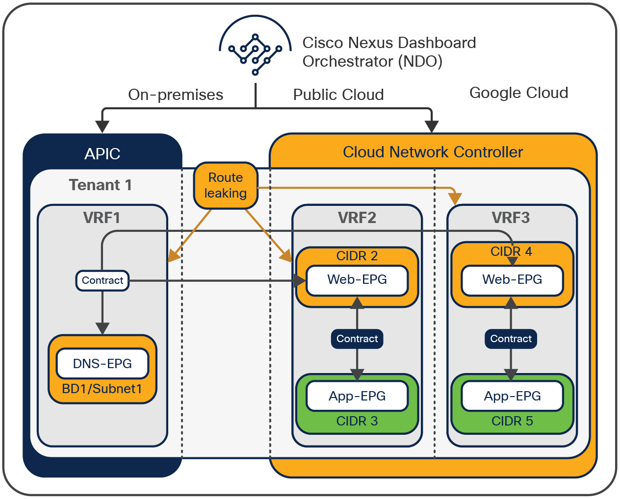
Cross-site shared services
External connectivity to the internet through the cloud or on-premises
External connectivity to the internet for workloads in GCP Cloud can be configured in two ways:
● Cloud L3Out: A cloud-local internet connection (also called L3Out in Cisco ACI terminology) can be defined for workloads deployed on GCP. It is achieved by configuring a cloud-external EPG in NDO for the cloud site in GCP. Once an EPG has a contract with the cloud-external EPG, security rules will be created as the firewall rules on GCP site through NDO, so that workloads in the EPG can reach the external network. Appropriate routes will be programmed into the VPC by GCP internally.
● On-premises L3Out: Some customer environments require all the traffic from a VPC in GCP to transit to an on-premises site and be inspected through an on-premises firewall/IDS/IPS before the traffic exits to, or enters from, the internet. This can also be achieved by defining an on-premises L3Out as the internet exit for traffic and associating the cloud endpoints to that EPG through a contract.
Customers have full control over external network connectivity options for workloads deployed in the cloud and can choose to redirect the traffic for inspection by various services deployed on premises by using Cisco ACI service graphs. All this can be done through a single policy, and end-to-end connectivity can be automated and orchestrated by Cisco Nexus Dashboard Orchestrator, greatly simplifying the operational workflows.
Example: When an administrator configures a cloud-local L3Out in the GCP environment (as shown in Figure 15), each GCP VPC will have external connectivity, and the GCP virtual machines in the VPC can directly communicate with the internet based on the policies defined.
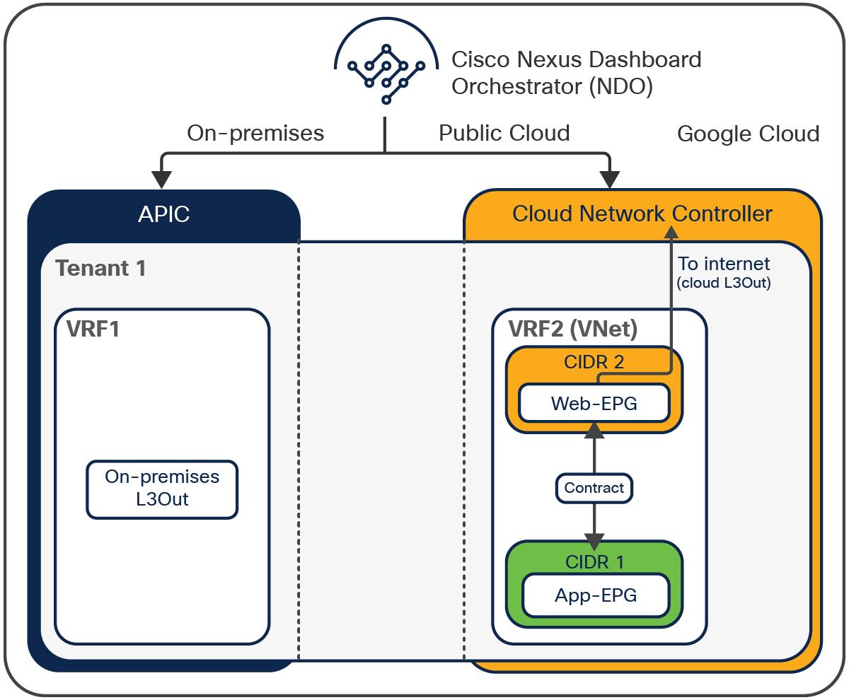
An example of cloud L3Out
If the administrator defines an on-premises Cisco ACI L3Out (as shown in Figure 16) and forces cloud instances to use that L3Out, then all traffic from GCP virtual machines reaches the cloud router through the VPN tunnels, and will be sent on premises over the VXLAN tunnel running over the IPsec tunnel. Traffic can then exit through the on-premises Cisco ACI L3Out instead of using the internet access from VPC directly.
Once traffic reaches the on-premises Cisco ACI site, the administrator may choose to subject this traffic to various inspections using the service chain options in Cisco ACI and then let the traffic exit to the Internet.
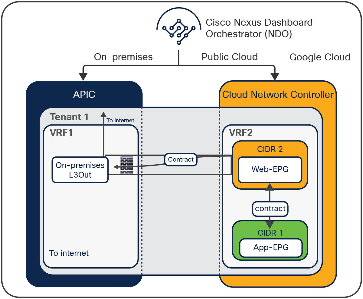
An example of on-premises L3Out for cloud endpoints
External site connectivity with Google Cloud Router and Cloud VPN Gateway
When Google Cloud Router and Cloud VPN Gateway are used to connect to another site, IP subnets are used to identify the external EPGs for the networks in the other site.
If the external site is an on-premises ACI fabric (Figure 11), NDO manages tenant configuration for both the on-premises ACI site and the cloud site, though the tenant configurations are independent. Figure 17 illustrates an example of this scenario. An external EPG is used to classify endpoints belonging to a subnet outside of the site (for example, 10.1.1.0/24 is external EPG “Onprem-App” in the cloud site to classify application endpoints that are in App-EPG1 in the on-premises ACI site). A contract between an external EPG and a site-local EPG is used to permit traffic between the external subnet and the site local EPG.
In this example, workloads that are part of the Web-EPG deployed on the cloud site can access these App services that are classified as the external EPG “Onprem-App” in the cloud site (subnet 10.1.1.0/24). Web-EPG subnet is classified as the external EPG “GCP-Web” in the on-premises ACI site (subnet 192.168.1.0/24).
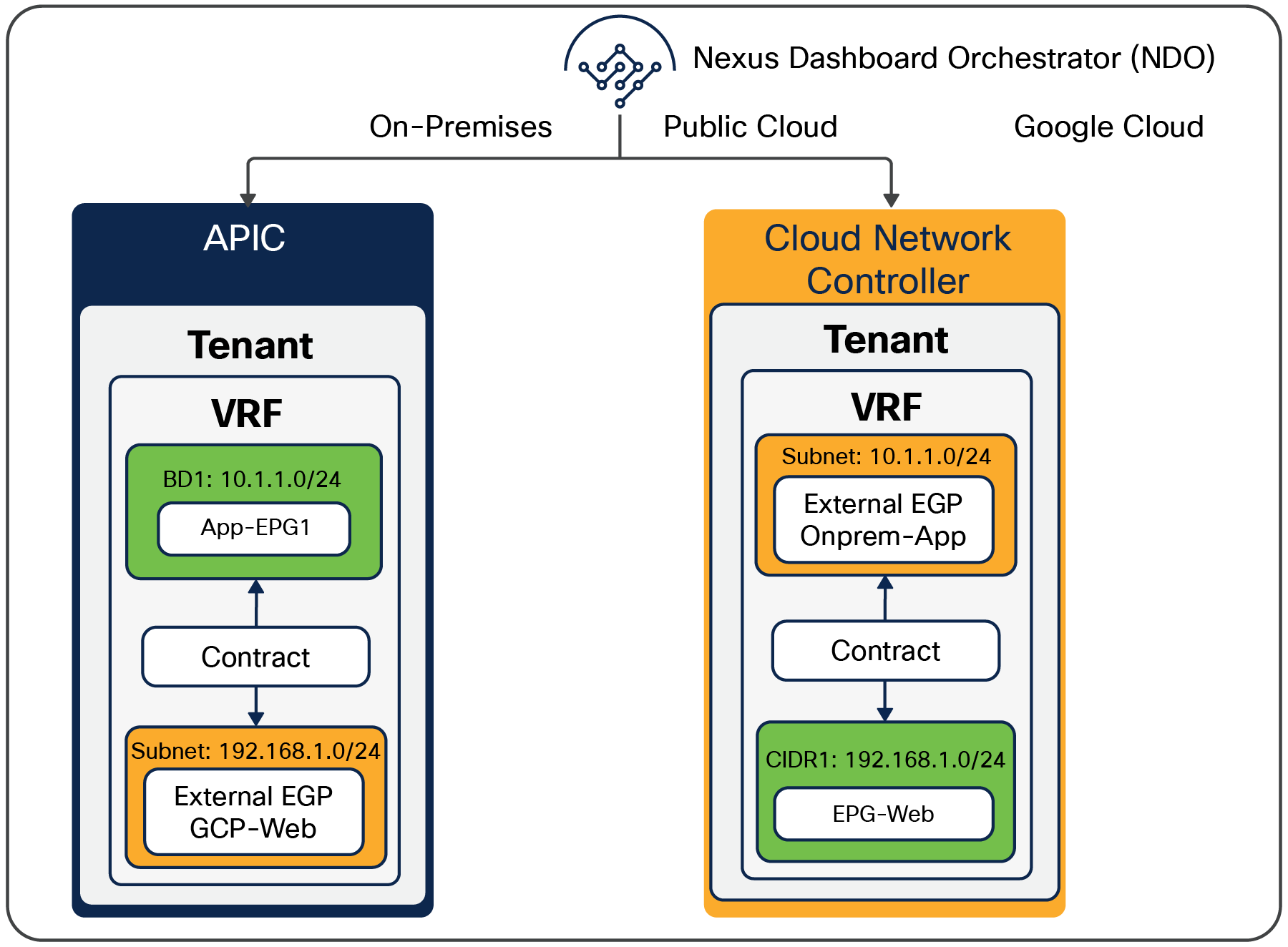
An example of an external site to cloud endpoints
Brownfield use case
The Cisco Cloud Network Controller supports the import of the existing brownfield VPCs and automates network and security policy connectivity from Cisco Cloud Network Controller-managed projects, including VPCs and firewall rules. Depending on the Access Policy configuration, what Cisco Cloud Network Controller manages in the brownfield VPC are different. Access Policy defines a privilege of Cisco Cloud Network Controller for each resource, such as tenant, VPC, and subnet.
The options for Access Policies are as follows:
● Read only: Cisco Cloud Network Controller doesn’t configure or provision anything in existing brownfield projects. The assumption is that security and routing in existing brownfield projects will still be owned by the user.
● Routing only: Cisco Cloud Network Controller controls the routing configuration in existing brownfield projects. The assumption is that security in existing brownfield projects will still be owned by the user.
● Routing and security: Cisco Cloud Network Controller controls both routing and security configurations in existing brownfield projects. As of Cisco Cloud Network Controller Release 25.1(1), this option is not available for the Cisco Multi- Cloud Networking solution with GCP.
Figures 18 to 21 illustrate an example of the brownfield import with “Routing only” Access Policy, where there is an existing brownfield VPC (brown1 VPC) that has not been managed by Cisco Cloud Network Controller yet, along with a greenfield VPC (green VPC) that is managed by Cisco Cloud Network Controller.
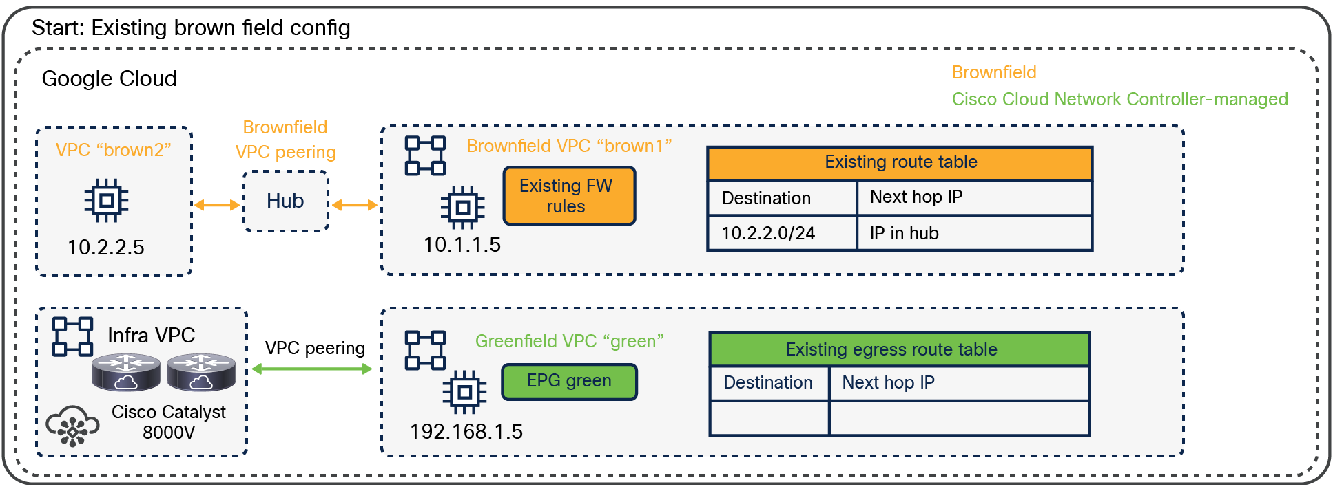
An example of a brownfield VPC: before importing a brownfield VPC
When you select a subnet from a brownfield VPC to import, if “VPC Hub Peering" option is selected, Cisco Cloud Network Controller automatically initiates a VPC-peering request between the brownfield VPC “brown1” and the infra VPC. At this moment, VMs in the brownfield VPC “brown1” should still have connectivity to the other brownfield VPC (brown2 in this example) because the next-hop IP is still the IP through the existing brownfield VPC peering.
In the case of “Read only” Access Policy, the VPC-peering configuration in the brownfield VPC is not updated by Cisco Cloud Network Controller.
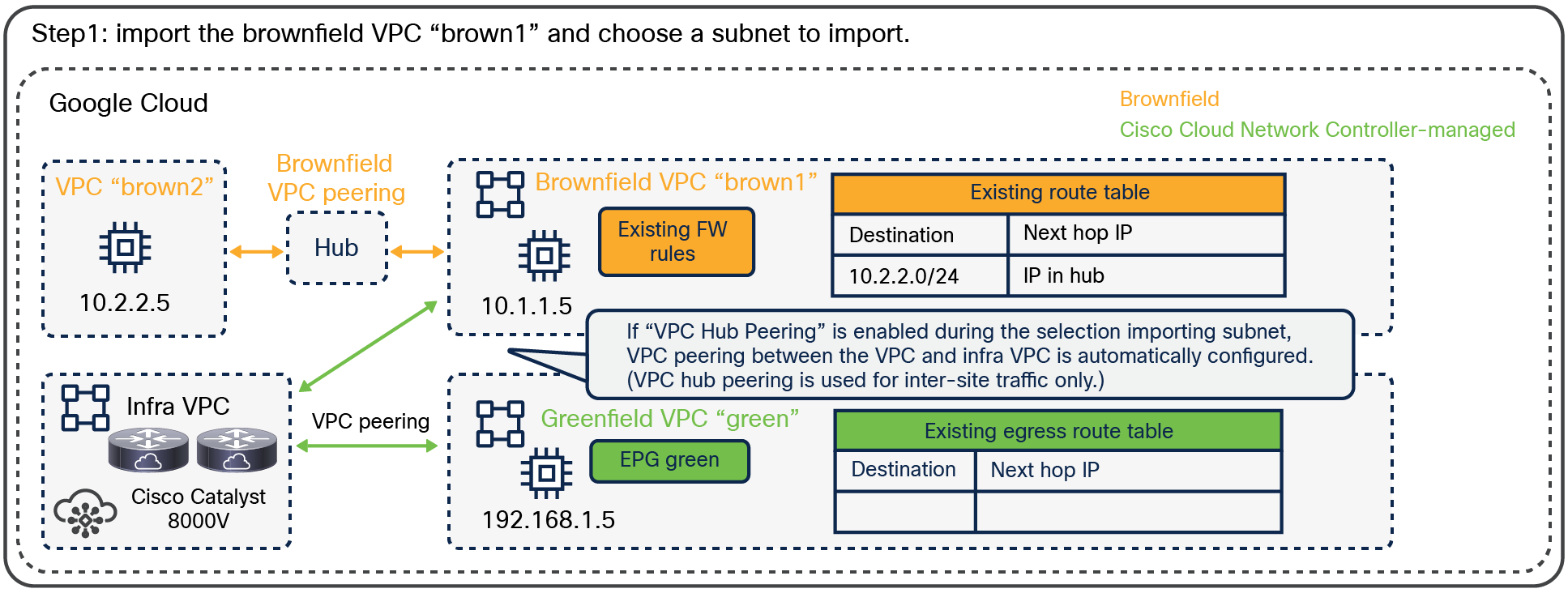
An example of a brownfield VPC: after importing a brownfield VPC
If “Contract Based Routing” is enabled, once a contract is applied between a greenfield EPG and a brownfield EPG, Cisco Cloud Network Controller automatically initiates a VPC-peering request between the brownfield VPC “brown1” and the greenfield VPC, and egress route tables on both VPCs are updated accordingly (as shown in the figure below), so that the VMs in the brownfield VPC “brown1” can reach the subnet in the greenfield VPC and also the subnet in brownfield VPC “brown2.”
In this example, because of a contract between EPG green and EPG brown1, VPC peering between brown1 VPC and green VPC is created along with the 192.168.1.0/24 route on the brown1 VPC route table and the 10.1.1.0/24 route on the green VPC.
Since the Access Policy is “Routing only,” it is the end user’s responsibility to configure or edit the firewall rule to allow proper communication between the greenfield EPG and the brownfield EPG.
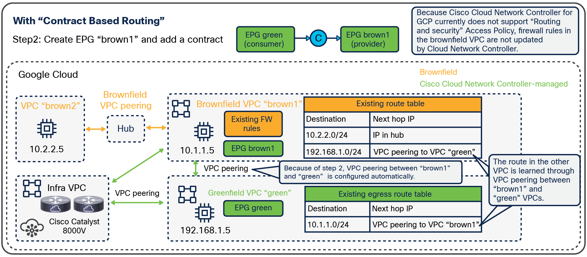
An example of a brownfield VPC: after creating a contract (Contract Based Routing is enabled)
If “Contract Based Routing” is disabled, VPC peering and route tables are not automatically configured based on a contract but based on route-leaking configuration.
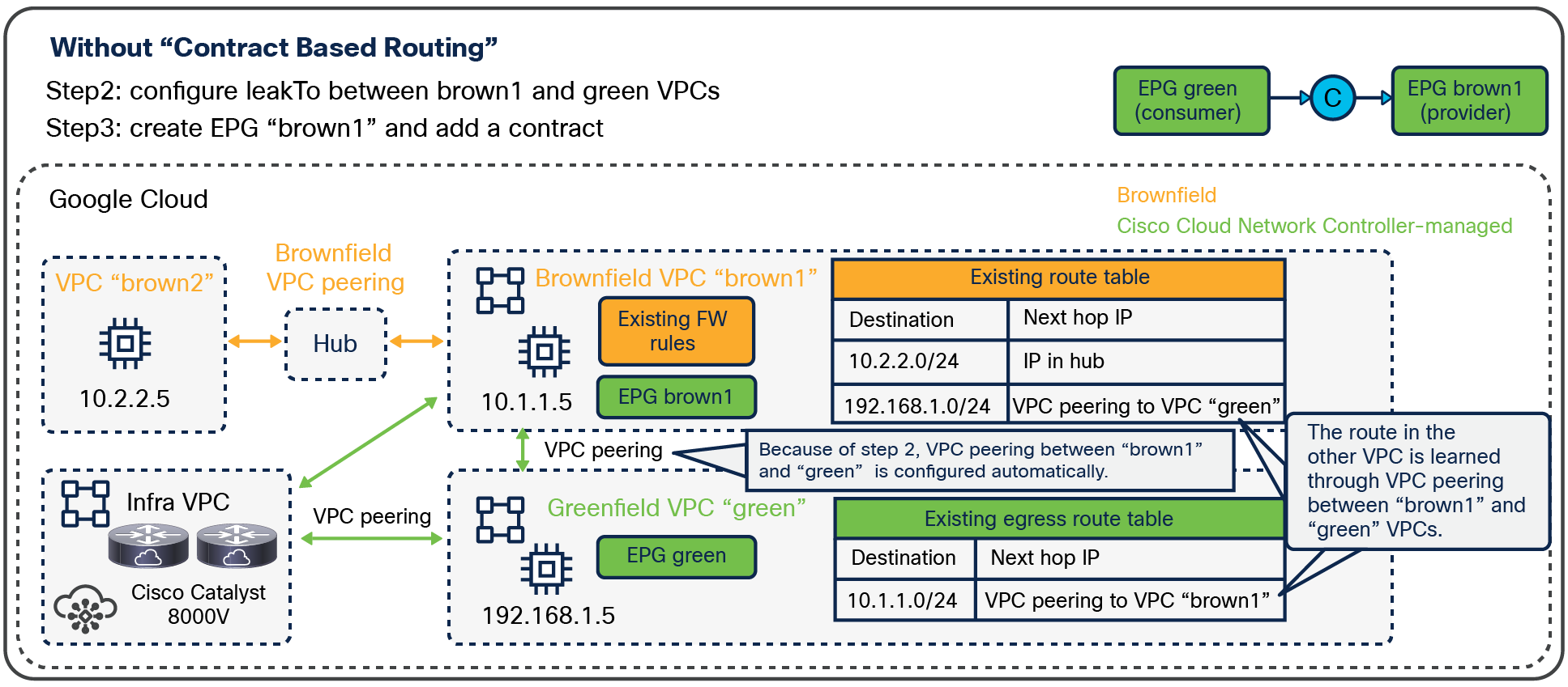
An example of a brownfield VPC: after creating a contract (Contract Based Routing is disabled)
Cloud-sites-only deployment
Cisco Multi-Cloud Networking solution supports multi-cloud deployments with cloud sites only, that is, without an on-premises ACI site. The cloud sites can be on any supported public clouds, including AWS, Microsoft Azure and GCP. Each cloud site can consist of multiple regions on the corresponding public cloud. Figure 22 shows a cloud-sites-only deployment with multiple cloud sites within GCP, each having two regions. Figure 23 shows a cloud-sites-only deployment with cloud sites on different supported public clouds.
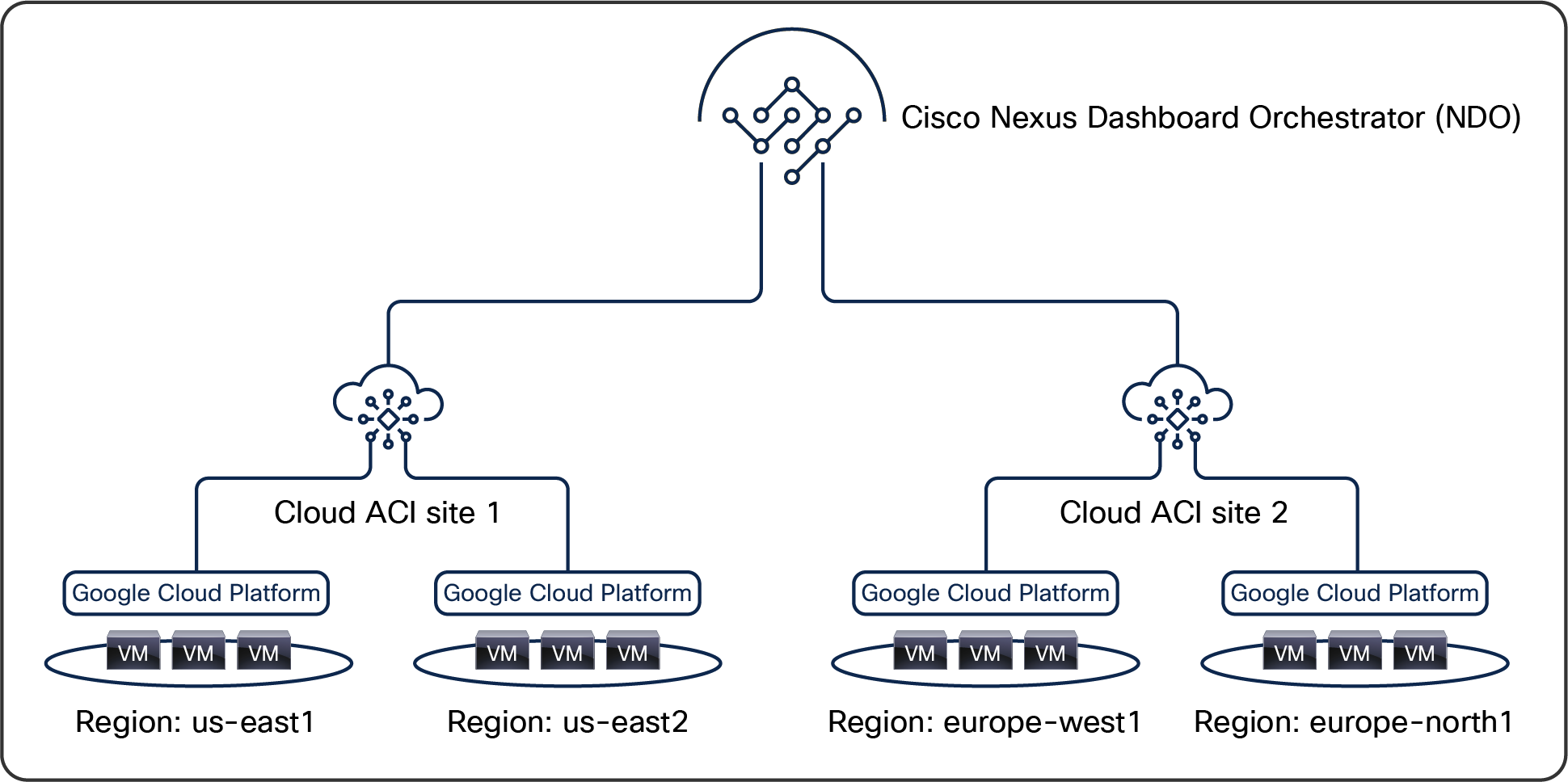
Multiple cloud sites within GCP
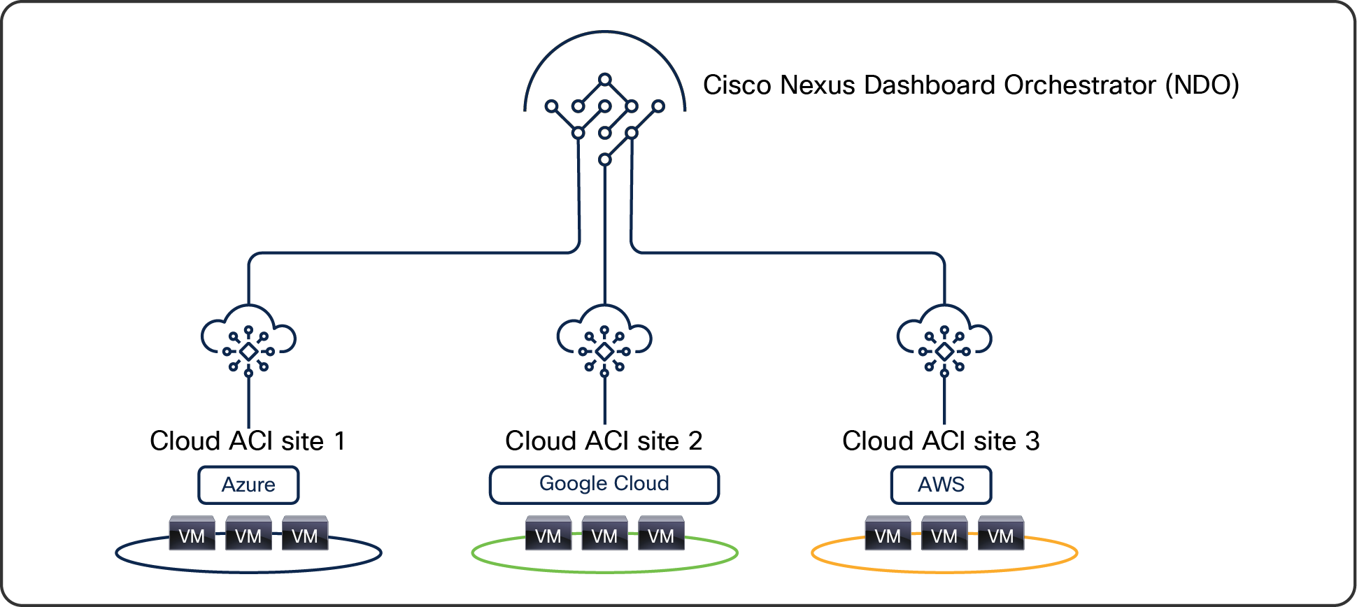
Multiple cloud sites on different public clouds
In a cloud-sites-only deployment, the network policies are still centrally defined on Cisco Nexus Dashboard Orchestrator (NDO) and distributed to the desired cloud sites. Even without an on-premises ACI site, Cisco Multi-Cloud Networking solution offers the same benefits mentioned earlier in this document. Especially for multi-cloud environments where each cloud has different cloud-native policy constructs, NDO contributes to operational simplicity by representing a single pane of glass for the provisioning of the configuration in different cloud sites. The site-local Cisco Cloud Network Controller translates the network policies to the cloud-native policy model and deploys the cloud-native network infrastructure for that site. NDO automatically programs the cloud routers such as Cisco Cloud Services Routers 1000v Series (prior to Cisco Cloud Network Controller Release 25.0(5)), Cisco Catalyst 8000V series routers, and cloud-native routers in the cloud sites to establish intersite connectivity using IPsec tunnels. It also configures BGP EVPN as the control plane between the cloud routers to exchange routes over the IPsec tunnel. VXLAN tunnels are then established between cloud routers for intersite data transfer. Unless an on-premises-specific feature is included, the use cases mentioned in the previous section are applicable to a cloud-sites-only deployment too.
Deploying Cisco Cloud Network Controller
The Cisco Cloud Network Controller network virtual appliance is available at GCP Marketplace and uses the BYOL model for licensing at the time of the writing of this white paper. Readers are encouraged to refer to the ordering guide for any other options.
The first step to deploy Cisco Multi-Cloud Networking solution is to launch Cisco Cloud Network Controller in GCP in a project for infra tenant.
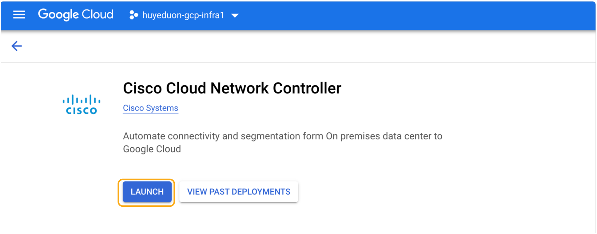
Cisco Cloud Network Controller in GCP Marketplace
Once Cisco Cloud Network Controller is deployed successfully, your Cisco Cloud Network Controller becomes accessible through its Web UI and API. As shown in Figure 25, you can find the public IP address of Cisco Cloud Network Controller. Connect to the Cisco Cloud Network Controller UI to complete the installation through the getting-started wizard.
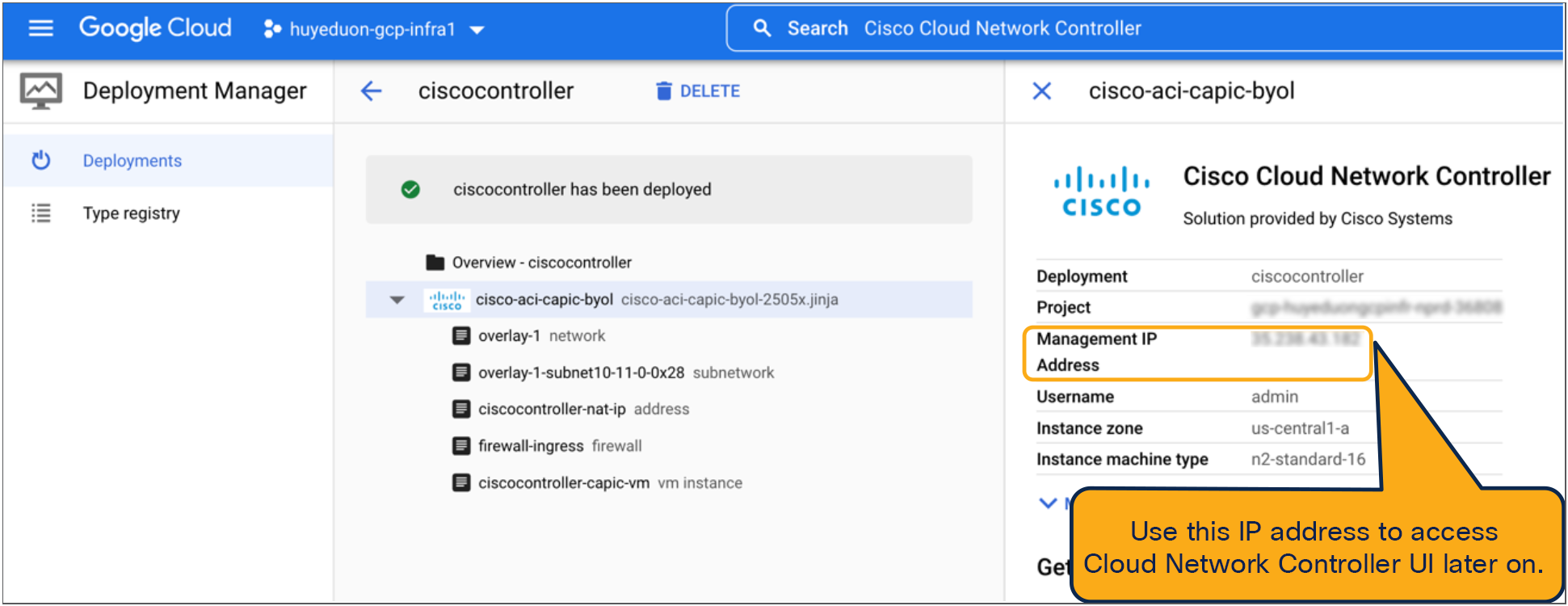
Cisco Cloud Network Controller virtual machine with public IP address
Cisco Cloud Network Controller’s First Time Setup wizard
The first time you connect to Cisco Cloud Network Controller UI, the First Time Setup wizard (shown in Figure 26) automatically kicks off. This wizard helps you configure some of the Cisco Cloud Network Controller required settings, such as DNS, the TEP pool, the regions to be managed, and IPsec connectivity options. At the end of the First Time Setup wizard, Cisco Cloud Network Controller configures the GCP infrastructure needed to become fully operational, such as the pair cloud routers. The provisioning of the GCP infrastructure is fully automated and carried out by Cisco Cloud Network Controller. After this step, you will be able to start deploying your Cisco ACI policy on GCP.
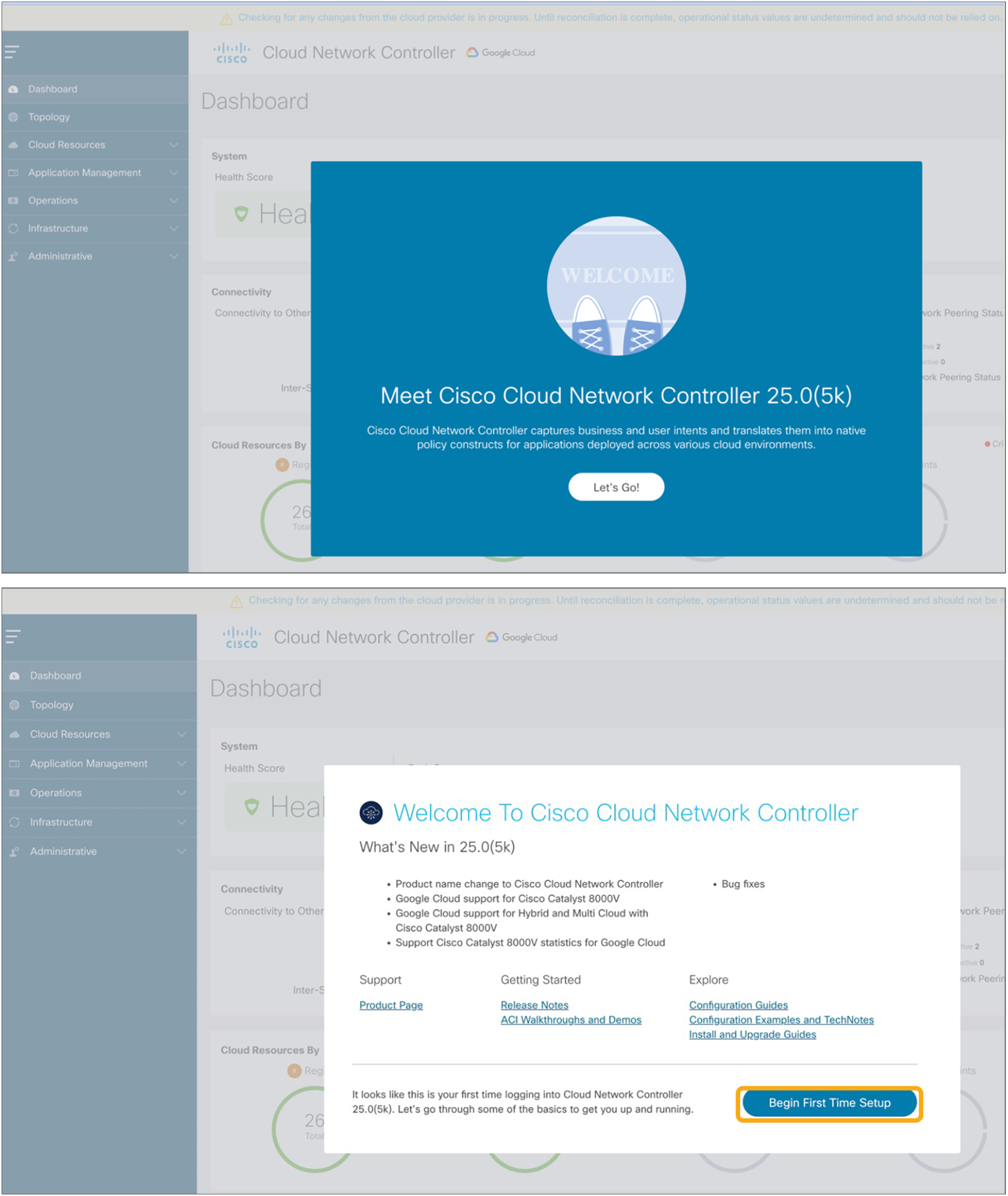
First Time Setup wizard of Cisco Cloud Network Controller
Registering a Cisco ACI cloud site in NDO
Each Cisco Cloud Network Controller represents a Cisco ACI site. To extend policy across sites, the Cisco Multi-Cloud Networking solution uses the Cisco Nexus Dashboard Orchestrator (NDO). As shown in Figure 27, when you register a Cisco Cloud Network Controller in NDO, it will appear as a new site and will allow you to deploy existing or new schemas to GCP. NDO ensures that you specify the required site-specific options, such as subnets and EPG membership classification criteria, which are different for each site.
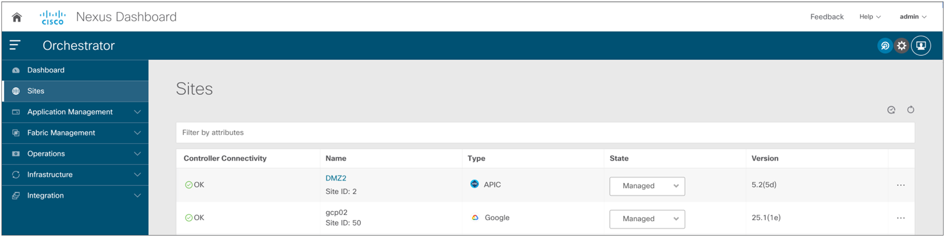
Register a Cisco ACI Cloud site in NDO
Cisco Cloud Network Controller lets you create networks on GCP using the Cisco ACI object model representation. In the backend, Cisco Cloud Network Controller translates Cisco ACI objects into GCP-native constructs. This means that the Cisco Multi-Cloud Networking solution adheres to GCP networking specifications. Because those differ slightly from what you might be used to with Cisco ACI, they are detailed below.
As shown in Figure 28, in GCP, a subnet is bound to a VPC, which itself is bound to a region. A VPC and a subnet span multiple zones in the region.
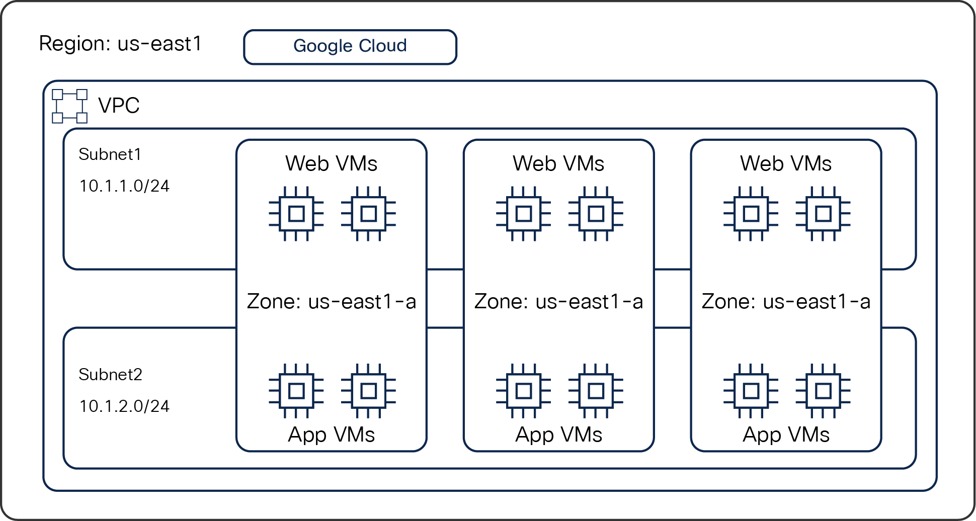
GCP-native network construct
Note: If you have existing VPCs and subnets that need to connect to VPCs and subnets created through Cisco Cloud Network Controller, please see “Importing Existing Brownfield Azure Cloud VPCs Into Cisco Cloud Network Controller”
This means that there is no concept of extending L2 from one VPC to another VPC or from the on-premises site to a VPC in GCP. To respect this design philosophy, Cisco Multi-Cloud Networking solution extends on-premises networks using L3 only.
Cisco Cloud Network Controller also provides a view of the GCP-native constructs used to represent the Cisco ACI policy. This allows network administrators to slowly familiarize themselves with GCP networking constructs. Figure 29 below demonstrates the native cloud resources view on the Cloud Network Controller UI. As an example, it displays the provisioned GCP VPCs in a cloud site.
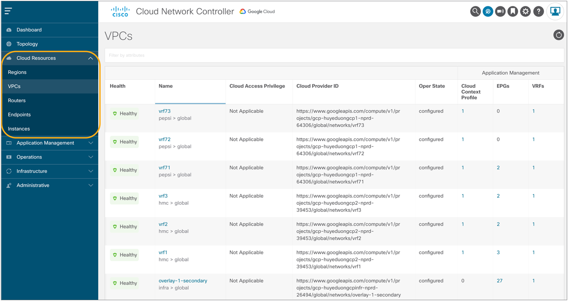
Native-cloud-resources view on the Cisco Cloud Network Controller user interface
Deploying a multi-tier application in a hybrid scenario
We use a classic three-tier application as an example in this session. The application consists of a database (DB), App, and Web tier. To deploy it across an on-premises data center and the GCP cloud using Cisco Multi-Cloud Networking solution, you will need to configure a schema on NDO that represents this policy. As shown in Figure 30, it should contain at least one VRF, one Application Profile, and EPGs as well as contracts between the tiers. For example, the DB tier can be deployed on premises and the Web tier in GCP. Or you can use any permutation of this set as you see fit, including (as explained previously) the option to stretch one or more EPGs between the on-premises data center and the cloud.
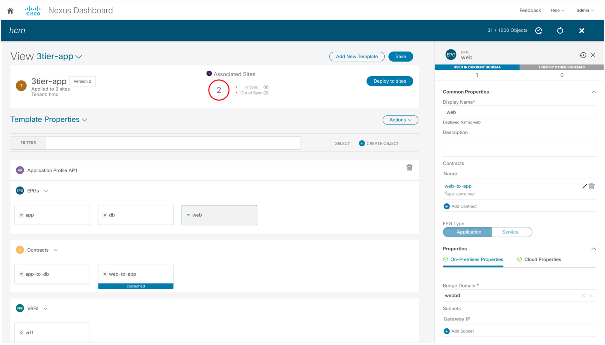
Application schema on NDO
The schema can then be associated with the on-premises site and the cloud site. Once the association is made, you then define the subnets to be used for the VRF on GCP. The Cisco Cloud Network Controller model associates BD subnets to VRF because, in GCP, VRFs are mapped to VPCs and subnets are in a VPC. Though a VPC and a subnet span multiple availability zones, there is no concept of extending L2 from the on-premises site to a VPC in GCP This means that you need to define a separate subnet for the Web EPG in each site. You will also define the membership criteria for cloud instances to join the Web EPG. As shown in Figure 31, once you are satisfied with the NDO schema and you have completed the required site-specific configuration steps, you can deploy the configuration to both Cisco ACI sites using the NDO one-click deployment button.
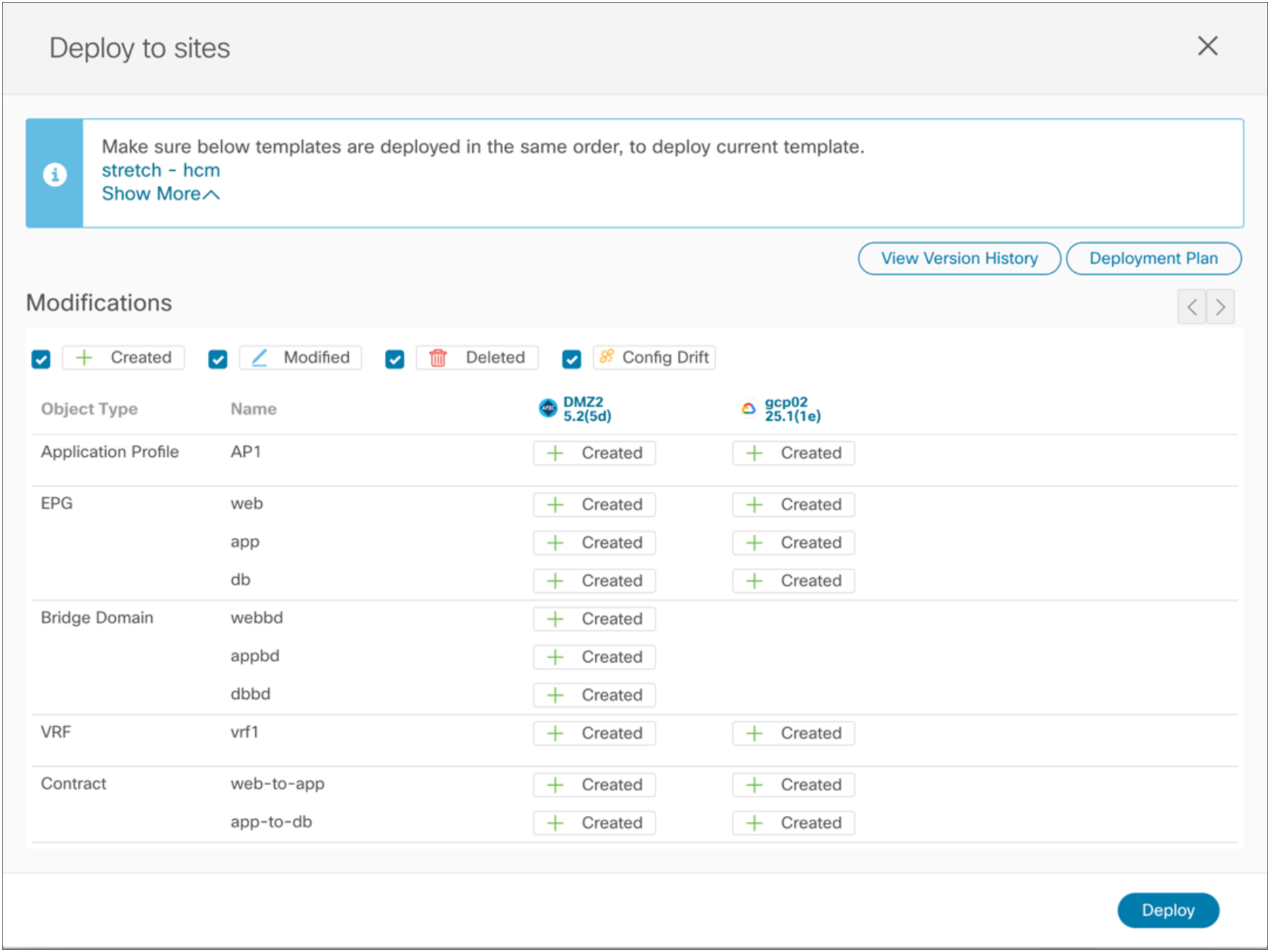
Deploy application to on-premises and cloud sites in GCP
The Cisco Multi-Cloud Networking solution ensures that the GCP cloud and on-premises ACI are configured appropriately to allow communication between the App EPG and the Web EPG residing on GCP, as shown in Figure 32.
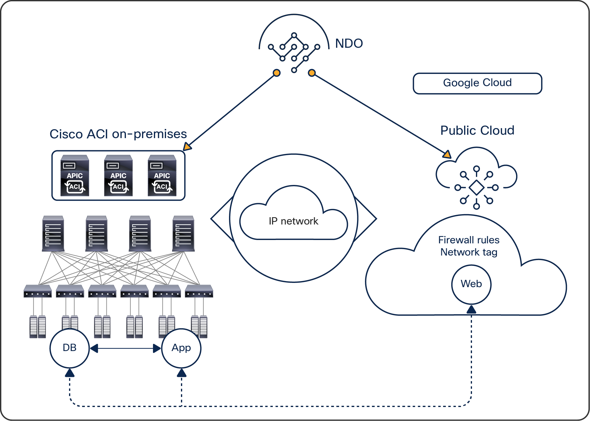
Three-tier application deployed across on-premises and cloud sites in GCP
You can now deploy new Web instances on GCP to accommodate your needs.
The new Cisco Multi-Cloud Networking solution capabilities delivered in Cisco Cloud Network Controller Release 4.1 with AWS, Release 4.2 with Microsoft Azure, and Release 25.0(3) with GCP make it easy for network administrators to quickly tailor the infrastructure to adapt to constantly evolving business requirements. The solution provides ultimate IT agility by greatly facilitating the configuration and day-2 operation of hybrid cloud environments. Cisco Multi-Cloud Networking solution lets you architect complex network topologies and security policies that encompass on-premises locations and public cloud sites. Cross-site orchestration of network connectivity and workload segmentation policies is achieved by Cisco Nexus Dashboard Orchestrator (NDO) working in tandem with Cisco Cloud Network Controller and on-premises APIC.
[1] See the data sheet and release notes for public cloud environment support information.