Application Hosting on Catalyst Access Points Deployment Guide
Available Languages
Bias-Free Language
The documentation set for this product strives to use bias-free language. For the purposes of this documentation set, bias-free is defined as language that does not imply discrimination based on age, disability, gender, racial identity, ethnic identity, sexual orientation, socioeconomic status, and intersectionality. Exceptions may be present in the documentation due to language that is hardcoded in the user interfaces of the product software, language used based on RFP documentation, or language that is used by a referenced third-party product. Learn more about how Cisco is using Inclusive Language.
Enterprise wireless networks are a rapidly growing part of today’s technology. They are becoming more mission-critical each day as new companies migrate to wireless solutions as a means to run their business. As wireless networks grow exponentially, we as a society are becoming more connected than ever before, giving us the ability to solve once seemingly complex problems with simple yet elegant solutions. However, these endless technological possibilities have also triggered a surge of both dependency and the expectation that technology must continue to better every aspect of our daily lives. The Internet of Things (IoT) has arisen, in part, as a result of these expectations, and Cisco’s state-of-the-art technology known as Application Hosting on Catalyst Access Points was created to help spearhead this movement.
Cisco’s Application Hosting on Catalyst Access Points feature provides users with the ability to load third-party containerized Cisco® IOx applications directly onto Cisco Catalyst™ access points and to leverage them as an IoT gateway. Once loaded, the third-party application gains complete access to specific access point software and hardware resources. Depending on the IOx application developed, it is able to promptly communicate with third-party software through its internal VLAN, or with hardware through its external-facing USB port. A typical business running a Cisco powered wireless infrastructure will have access points deployed throughout all employee-inhabited facilities. Giving third-party vendors the ability to create applications and leverage these access points as IoT gateways has created endless possibilities for the IoT movement.
This document covers the deployment of Application Hosting on Catalyst Access Points feature with Cisco Catalyst Center.
Disclaimer: Cisco claims customer support for any application lifecycle management issues; however, for any problems related to a Cisco partner’s IoT USB connector, application server, or IoT device, please reach out to them directly.
Supported software
Table 1. Cisco Catalyst Center and Cisco IOS® XE software compatibility matrix
| Cisco Catalyst Center software release |
Cisco IOS XE WLC software release |
| 2.1.2.x and above |
17.3.1 and above |
Supported hardware
Table 2. Supported access points
| Access point product ID |
OS type |
| C9105AXI |
AP-COS |
| C9105AXW |
AP-COS |
| C9115AX |
AP-COS |
| C9117AX |
AP-COS |
| C9120AX |
AP-COS |
| C9130AX |
AP-COS |
| C9124AX |
AP-COS |
| C9136I |
AP-COS |
| C9162I |
AP-COS |
| C9164I |
AP-COS |
| C9166I |
AP-COS |
Note: C9136I is supported starting from Cisco IOS XE Release 17.7.1.
Note: CW9164I/9166I is supported starting from Cisco IOS XE Release 17.9.1.
Note: CW9162I is supported starting from Cisco IOS XE Release 17.9.2/17.10.1.
Note: CW9166D1 is supported starting from Cisco IOS XE Release 17.12.1.
Table 3. Supported wireless LAN controllers
| Wireless LAN controller product ID |
OS type |
| C9800-CL |
Cisco IOS XE |
| C9800-L |
Cisco IOS XE |
| C9800-40 |
Cisco IOS XE |
| C9800-80 |
Cisco IOS XE |
Prerequisite: Installing the Application Hosting package from Cisco Catalyst Center
Cisco Catalyst Center provides the option to download a package called Application Hosting. You can download and install this package on top of the base Cisco Catalyst Center software.
● To install the Application Hosting package, log in to Cisco Catalyst Center and open the menu in the top left corner.
● Click System > Software Updates, then click Installed Apps on the left. Scroll down to Automation and you will find the package available for download or installation (Figure 1).
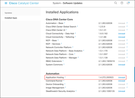
Location of the Application Hosting package
High-level deployment workflow
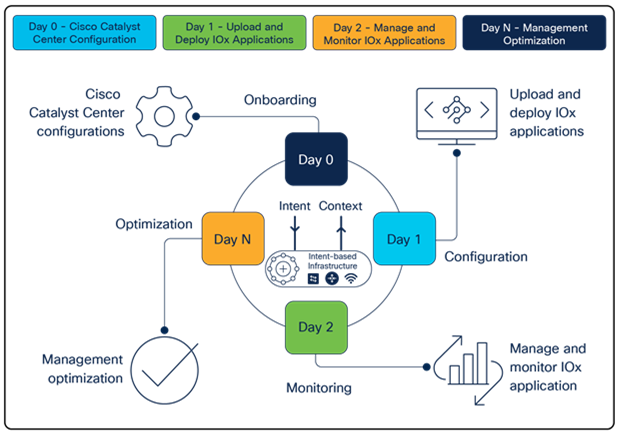
Steps for deploying Application Hosting
Day 0: Cisco Catalyst Center configurations
Note: Skip to day 1 if you have already completed day-0 Cisco Catalyst Center configuration.
● Create a network hierarchy site (area, building, floors) via the Network Hierarchy page.
● Optional: Configure the network hierarchy settings via the Network Settings page.
● Discover the wireless controller (WLC) and access points via the Discovery page.
● Assign the WLC and access points to the network hierarchy created via the Inventory page.
Day 1: Upload and deploy IOx applications
● Upload a third-party IOx application to Cisco Catalyst Center via the IoT Services page.
● Deploy the uploaded application to specific access points.
Day 2: Manage and monitor IOx applications
● Establish communication between the third-party application and its application server.
● Begin managing and monitoring the applications deployed on the access points.
Day N: Optimize management
● Validate how the deployed applications are performing in the field.
● Develop software enhancements based on analysis and upgrade your applications.
● Repeat the deployment workflow from day 1.
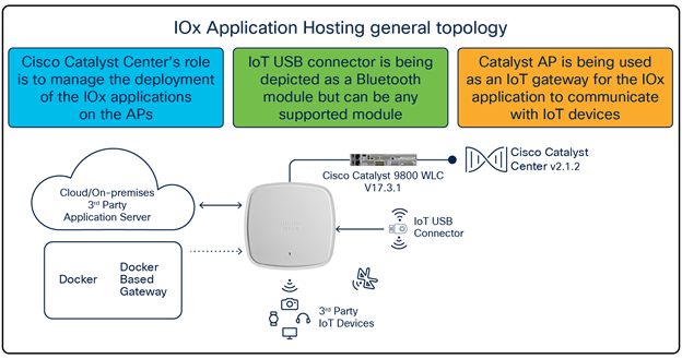
IOx Application Hosting general topology
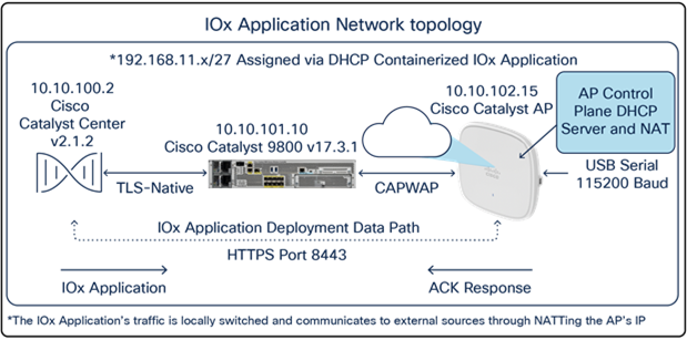
IOx Application Hosting network topology
By default, your application will receive an IP address from 192.168.11.x/27 through Dynamic Host Configuration Protocol (DHCP) and communicates externally from your access point through Network Address Translation (NAT). This means that the IOx application will by default have the same IP address as the access point from the perspective of external applications. If this is an issue, please refer to the data segmentation section below.
This section provides you with information about how the IOx application’s data is segmented when communicating externally from the access point.
With default settings, the IOx application deployed on the access point will communicate externally by using NAT to translate the AP’s management IP (Figure 5.). While this works fine, since the IOx application’s data uses the same VLAN as the access point’s traffic, there is no segmentation.
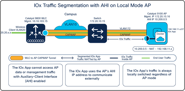
IOx traffic segmentation on a Local Mode access point
To configure proper segmentation, we can configure something known as an auxiliary-client interface (AHI) on an access point group within your WLC that’s associated with your Application Hosting access points.
Nolan_eWLC#config terminal
Nolan_eWLC(config)# <AP Join Profile Name>
Nolan_eWLC(config-ap-profile)# auxiliary-client interface vlan-id <VLAN ID>
Note: Ensure that the VLAN ID included in the command above exists within your controller.
After AHI is configured for your access point group, all access points within the access point group will now acquire an IP address from the AHI VLAN’s DHCP pool. When the IOx application needs to communicate externally, it will do so through the AHI’s IP rather than the access point's management IP. Since the IOx application and the access point's traffic now use different VLAN IDs, there is proper segmentation between the two. Observe that the same concept applies whether the access point is in Local or Cisco FlexConnect® mode and a Cisco fabric deployment. (see Figure 6 and Figure 7.)
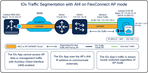
IOx traffic segmentation with an auxiliary-client interface configured on a FlexConnect Mode access point
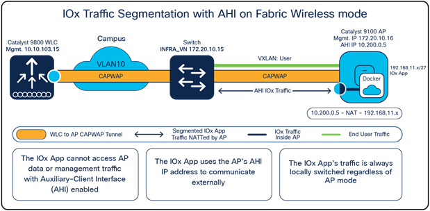
IOx traffic segmentation with an auxiliary-client interface configured in Fabric Wireless Mode
Day 0: Set up the Cisco Catalyst Center configuration
This section provides step-by-step instructions for the day-0 configuration necessary to begin using Application Hosting on Catalyst Access Points.
Note: Skip to the day-1 section if you have already completed day-0 Cisco Catalyst Center configuration.
Part 1: Day-0 configuration – Building a site hierarchy
Description: Cisco Catalyst Center’s Design page provides a robust design application that allow customers of every size and scale to easily define their physical sites and common resources.
Section goals: Create and configure network hierarchy sites and settings to define shared services, device credentials, and Simple Network Management Protocol (SNMP) community strings.
Step 1: Navigate to the Network Hierarchy page
● Option 1: Log in to Cisco Catalyst Center. Scroll down to the Network Configuration section and choose Design (Figure 8).
● Option 2: Click on the menu in the top left corner of the screen. Click Design and then Network Hierarchy (Figure 9).

Location of the Design page on Cisco Catalyst Center’s homepage
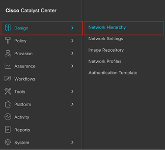
Location of Network Hierarchy from the menu
Step 2: Create sites, building, and floors
To allow Cisco Catalyst Center to group devices based on location, begin by laying out a hierarchy of areas, building, and floors as required to accurately represent the location of your network. A site hierarchy lets you enable unique network settings and IP spaces for different groups of devices.
● Option 1: To create a site, click the Add Site button (Figure 10). A menu will open up providing an option to create a child area, building, or floor within a desired site.
● Option 2: To create a site, click the gear icon (Figure 11) next to the site under which you would like to create a child site.
● When creating a floor, click Upload file to upload a floor of a building (Figure 12).
● Floor plans must be in the DXF, DWG, JPG, GIF, or PNG format.
The behavior of Cisco Catalyst Center is to inherit settings from the global level into subsequent levels in the hierarchy. This enables consistency across large domains while providing administrators the flexibility to adapt and change an individual building or floor.
Notes:
● You can create areas and buildings only within the Global site or other areas, and can create floors only within buildings.
● When creating a building within a design hierarchy, it is critical that you use a real physical street address for your sites. Cisco Catalyst Center uses the street address to select the country codes for the wireless implementation.
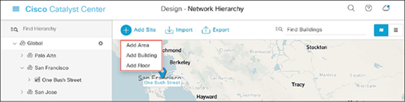
Clicking Add Site within the Design – Network Hierarchy page
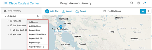
Clicking the gear icon next to an area within the Design – Network Hierarchy page
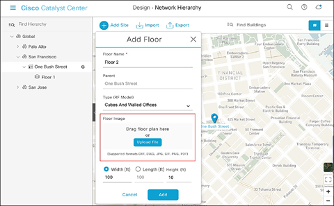
Location of the Upload file button to upload a floor plan during floor creation
Step 3: Navigate to the Network Settings page
Cisco Catalyst Center lets you save common resources and settings with the Network Settings application. Information pertaining to the enterprise can be stored and reused across the network.
● To navigate to the Network Settings page, open the menu in the top left corner of the screen. Click Design and then Network Settings (Figure 13).
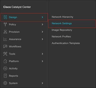
Location of Network Settings from the menu
Step 4: Configure network settings and device credentials
This is where you configure all device-related network settings. By default, Cisco Catalyst Center’s IP address is pre-populated in the Syslog Server and SNMP Server fields. This will enable syslog and Simple Network Management Protocol (SNMP) traps to be sent to Cisco Catalyst Center from network devices when a WLC is added to Cisco Catalyst Center.
● Click the Device Credentials sub-tab to view the existing device Command-Line Interface (CLI) credentials and SNMP community strings (Figure 14).
● Click the Add button to create new credential entries using the CLI Credentials form (Figure 15). Cisco Catalyst Center uses these credentials to discover the network devices.
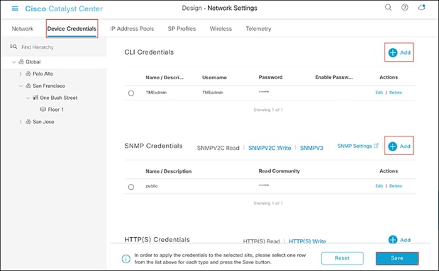
Adding device credentials to the network settings
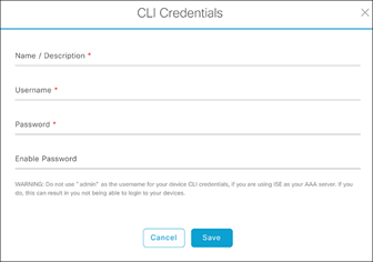
CLI Credentials form
Part 2: Day-0 configuration – Discovery and inventory
Description: Cisco Catalyst Center’s Discovery application allows a network administrator to add their network device to the platform.
Section goals: Discover the WLC and access points and assign them to the site created in the previous section.
Step 1: Navigate to the Discovery application
● Option 1: From the homepage, scroll down to the bottom and click Discovery and then Add Discovery (Figures 16 and 17).
● Option 2: Click on the menu in the top left corner of the screen. Click Tools and then Discovery (Figure 18).
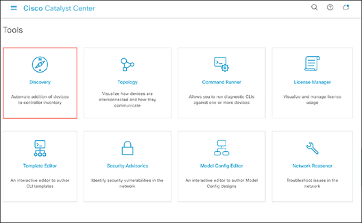
Location of Discovery button on the Cisco Catalyst Center homepage
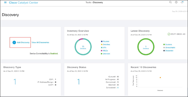
Location of the Add Discovery button on the Tools – Discovery page
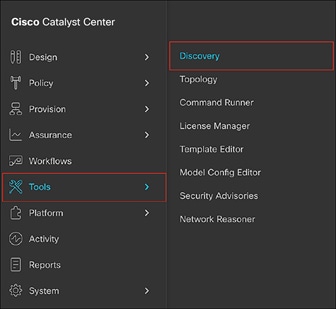
Location of Discovery within the menu
Step 2: Discover controllers and access points and add them to Cisco Catalyst Center
To discover a WLC and add it to Cisco Catalyst Center, follow the steps below (Figure 19):
● Enter a Discovery name (any unique name for the purpose of classification on the Discovery page).
● Enter either a single IP address or a range of IP addresses via one of the protocols (Cisco Discovery Protocol, range, or Link Layer Discovery Protocol [LLDP]).
● Warning: The WLC and access points must be on a routable network to Cisco Catalyst Center for Application Hosting on Catalyst Access Points to work. NAT networks are NOT supported, and neither are fabric networks.
● Enter the SSH username and password and SNMP read and write credentials (by clicking Add Credentials).
● If you’re discovering a Cisco IOS XE controller, enter the NETCONF port as 830 and run the following commands on the controller CLI:
◦ aaa new-model
◦ aaa authentication login default local
◦ aaa authorization exec default local
● When the details are filled in, click the Discover button.
Notes:
● When you discover a WLC, all of its joined access points will also be discovered and added to Cisco Catalyst Center’s inventory.
● All the CLI credentials defined in the Design section are displayed here on the Discovery page.
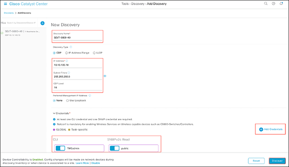
Discovery page with credentials filled in and ready for discovery
● After the discovery process completes, ensure that the status of ICMP (Internet Control Message Protocol), SNMP, and CLI is green for every device that has been discovered (Figure 20).
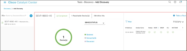
Successful discovery of a WLC as shown on the Discovery page
Step 3: Navigate to and manage inventory
After the discovery process is complete, navigate to the Inventory application, where your discovered devices will be listed.
● Open up the menu and click Provision and then Inventory (Figure 21).
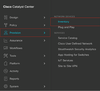
Location of Inventory within the menu
● Click Unassigned Devices on the left and ensure that all devices are Reachable and that their Manageability state is Managed (Figure 22).
● It is critical for all devices to be in the Managed state for Application Hosting functionality to work. If any are not, check the reachability of the devices.
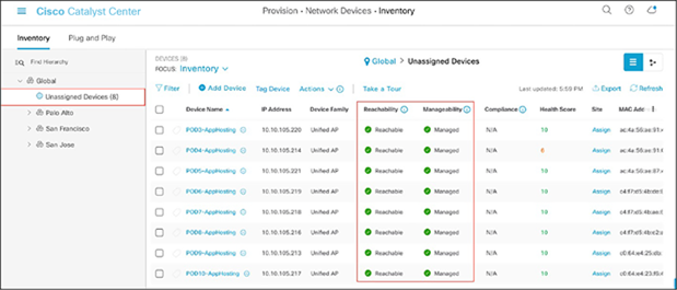
Reachability and Manageability status of discovered devices
● Optional: If you would like to manually add a controller to the inventory, click the Add Device button and provide the same information as was given in the Discovery application (Figure 23).
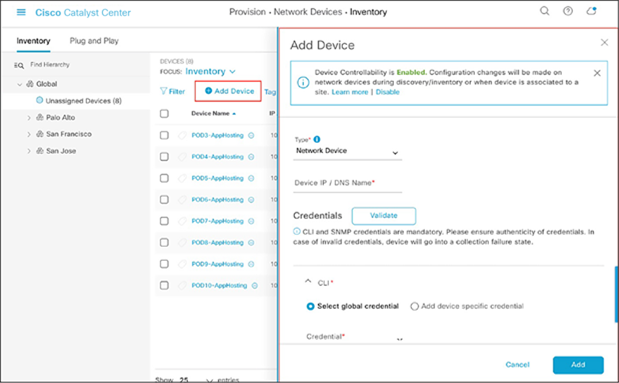
Add Device form
Step 4: Assign discovered devices to the site hierarchy
After discovery and site assignment, Cisco Catalyst Center will have automatically pushed/enabled the following configuration to the WLC and access points. This configuration is required for Application Hosting on Catalyst Access Points to work.
● Pushed a Cisco Catalyst Center certificate
● Configured Cisco Catalyst Center as an SNMP trap receiver
● Configured Cisco Catalyst Center as a syslog server
● Click the check box next to a device that you would like to assign to a site.
● Hover your cursor over Actions and then Provision, then click Assign Device to Site (Figure 24).
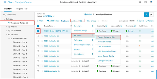
Assigning a WLC to a site on the Inventory page
● Click Choose a Site (Figure 25).
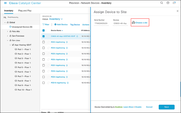
Assign Device to Site menu
● Click on the site to which you would like to assign the WLC and then click Save (Figure 26).
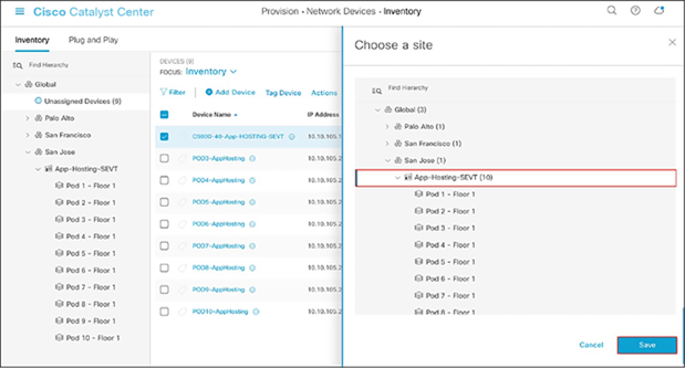
Choosing a site
● Click Next and then Assign.
● Repeat the same steps for your access points.
Step 5: Place your access points onto the floor map
The purpose of placing your access points onto your floor map is to provide you with a heat map visualization of the RF environment surrounding your access points.
Note: This step is not required for Application Hosting on Catalyst Access Points but is recommended to complete your day-0 configuration.
● Navigate to the Network Hierarchy page by opening the menu in the top left corner of the screen. Click Design and then Network Hierarchy (Figure 27).
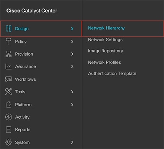
Location of Network Hierarchy in the menu
● Expand Global > [the building you created], then click on the floor you’ve assigned access points to.
● Observe the blue flag on the right, which indicates the number of access points that are ready to be placed onto the map (Figure 28).
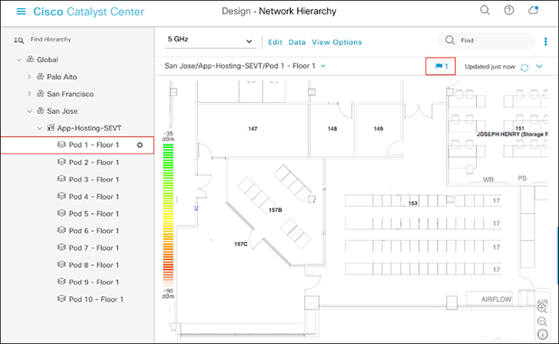
Network Hierarchy page, with an access point ready to be positioned
● Click Edit and then Position to place access points onto the map (Figure 29).
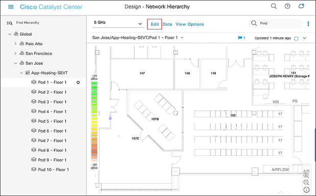
Network Hierarchy page – Floor elements menu
● After placing the access points on the floor map, click Save to commit the change (Figure 30).
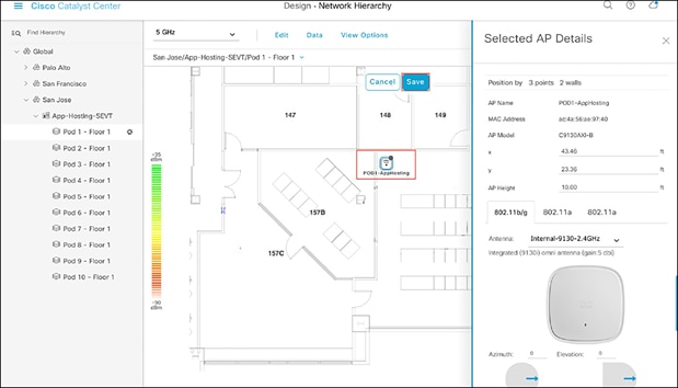
Network Hierarchy page, with access points placed on the floor map
● At this point, a color-coded heat map should show up on the floor map, depicting the access points’ surrounding RF environment (Figure 31).
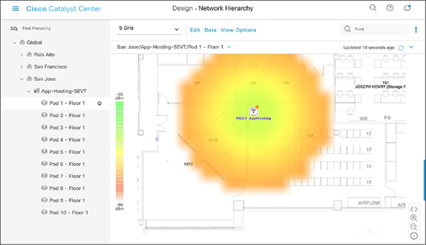
Network Hierarchy page, with heat map displayed after access points are positioned
Day 1: Upload and deploy an IOx application
This section provides step-by-step instructions for uploading an IOx application to Cisco Catalyst Center and then deploying it to the desired access points.
Part 1: Day-1 configuration – Uploading an IOx application
Description: Cisco Catalyst Center’s IoT Services page provides an intuitive way to upload and manage third-party applications that you would like to deploy on your access points.
Section goals: Upload an IOx application into Cisco Catalyst Center’s repository so it can be ready for deployment to the desired network hierarchy location or access point.
Step 1: Navigate to the IoT Services page
● Open the menu and click Provision and then IoT Services to enter the App Hosting page (Figure 32).
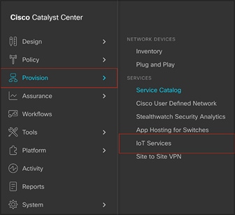
Location of IoT Services within the menu
Step 2: Upload the IOx application to Cisco Catalyst Center
● Click New Application on the right side of the screen (Figure 33).
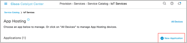
Location of the New Application button on the App Hosting page
● Click the Type drop-down menu and select an application type (Figure 34).
● Option 1: Docker
◦ Choose this option if the application you are uploading is a Docker app saved as a .tar file using the Docker Save command.
● Option 2: Cisco Package
◦ Choose this option if the application you are uploading has been packaged using the Cisco app-packaging toolchain.
● For more information regarding the package types above, visit the following link: https://developer.cisco.com/docs/iox/
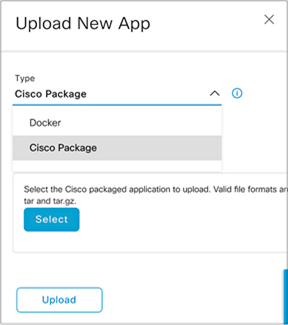
Choosing an application type
● Click the Category drop-down menu and select an application category (Figure 35).
● The categories are Monitoring, Security, IoT, and Others.
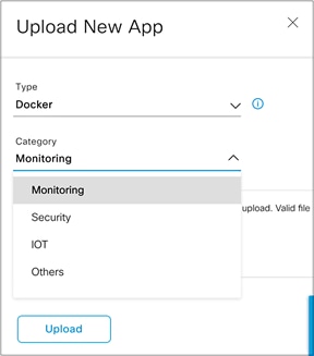
Choosing an application category
● Click the Select button and select a file to upload, then click Upload to upload the file (Figure 36).
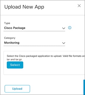
Location of the Select and Upload buttons
● Ensure that the application you’ve uploaded now appears within the App Hosting page (Figure 37).
● IOx applications can be discovered and downloaded via the following link: https://developer.cisco.com/ecosystem/spp/
◦ Optional: If you would like to manage the application, click on it to enter the application’s management page.
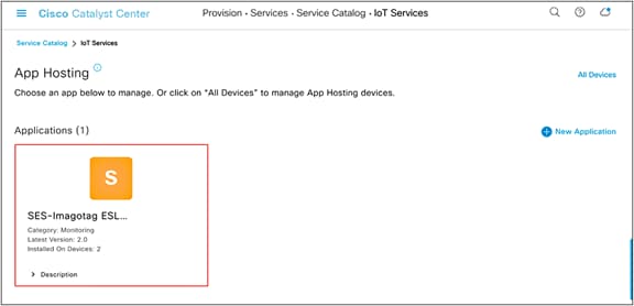
Location of an application after being uploaded
● (a) To upload a new version of this application, click the Update Application button. (b) To delete the application, click the Delete Application button. (c) To edit the application’s description, click the Edit button (Figure 38).
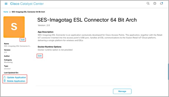
Application management page
Part 2: Day-1 configuration – Deploying an IOx application
Description: Cisco Catalyst Center’s Enable IoT Services workflow allows you to easily deploy your application to either a location or a specific access point.
Section goals: Deploy an IOx application to all devices within a network hierarchy site created earlier.
Step 1: Navigate to the Enable IoT Services workflow
● Open the menu, then click Workflows (Figure 39).
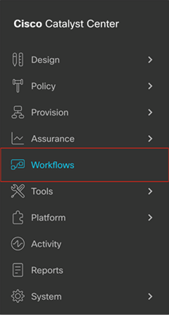
Location of Workflows on the menu.
● Scroll down and click on the grid labeled Enable IoT Services to begin the deployment workflow (Figure 40). Click the Let’s Do It button in the modal box that appears (Figure 41).
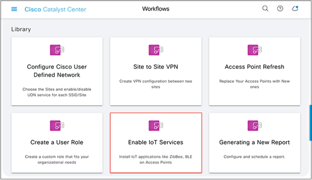
Location of the Enable IoT Services option
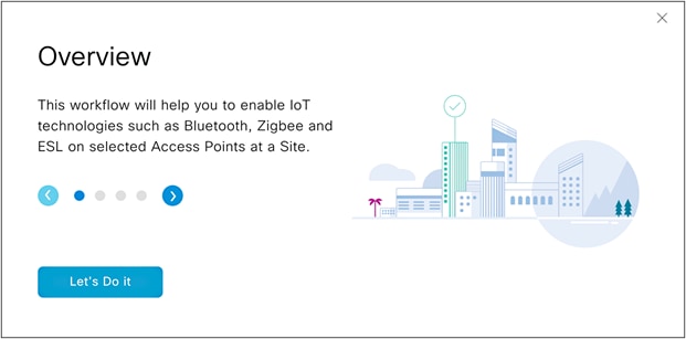
Modal box for the Enable IoT Services option
Step 2: Deploy the application to access points on a floor
● Select a floor within the network hierarchy where you’d like to deploy the application, then click Next (Figure 42).
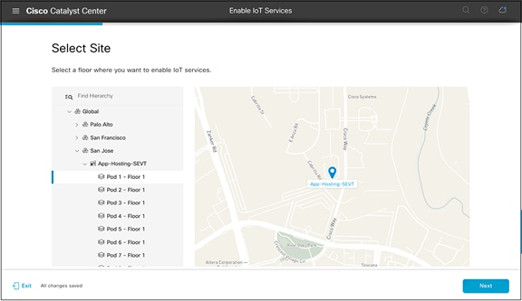
Selecting a floor
● Select the image that you would like to deploy to devices on that floor, then click Next (Figure 43).
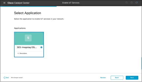
Selecting an application to deploy
● Select one or more access points on this floor that you would like to deploy the image to, then click Next.
● By default, the page will show an access point list view (Figure 44); however, this can be toggled by clicking on the map icon to show a network hierarchy floor view (Figure 45).
● Note: Make sure the Readiness column indicates Ready for the access points you select.
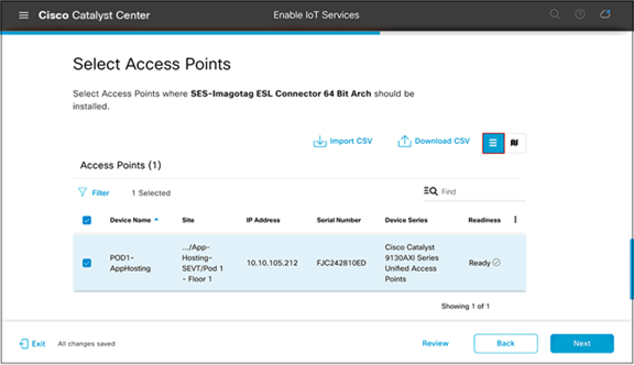
Selecting access points from the list
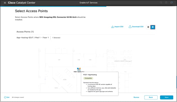
Selecting access points from the map
● On the Application Configuration page, input configurations for the IOx application specified by the IoT app vendor. These configurations will be implemented when the application is deployed to the AP (Figure 46).
● Example: The configuration can be used to point the IOx application to a specific application server.
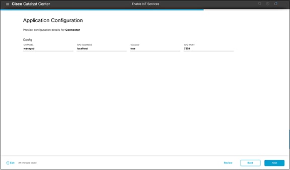
Adding configurations to your IOx application
● On the Summary page, check that the application is being deployed to the intended site and access points, then click Next (Figure 47).
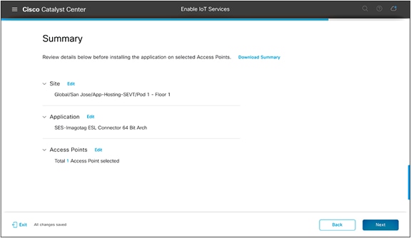
Summary page
● Note the task name for reference, then click Provision (Figure 48).
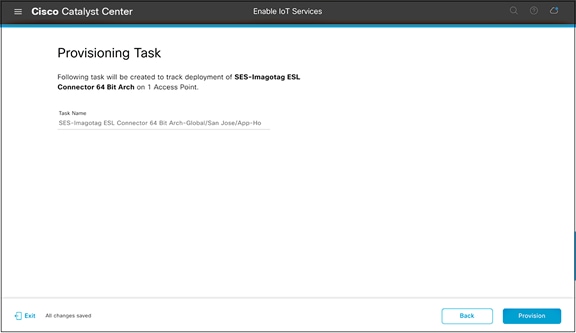
Generated provisioning task name
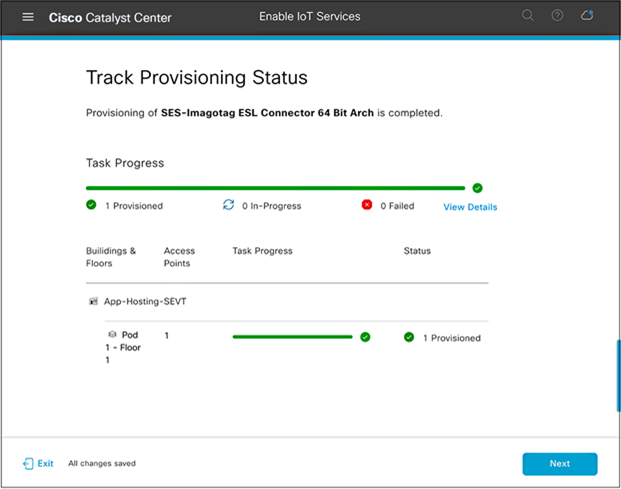
● The application deployment process will begin (Figure 49).
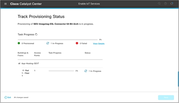
Track Provisioning Status page
● If all steps were followed, you will see a Provisioned message (Figure 50).
Warning: If you attempt to deploy an application with a dependency on a USB attachment and the attachment is not detected, you will see a Failed message.
● After verifying the provisioning status of your application deployment, click Next.
Success case when deploying an application to an access point
● Click the Manage IoT Application button to continue to the application’s management page (Figure 51).
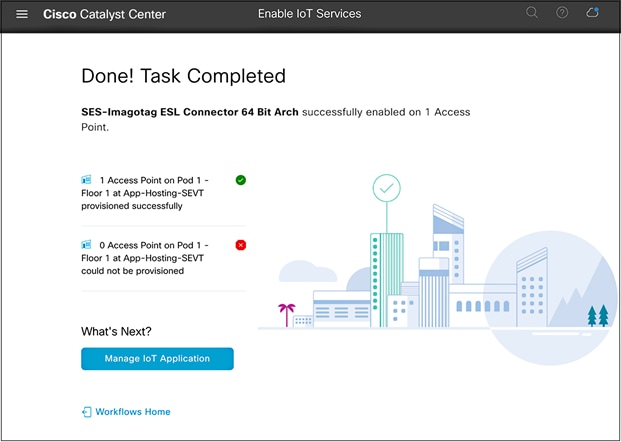
Enable IoT Services workflow summary page
● On this application management page, you’re able to manage the status of the applications deployed on your access points (Figure 52).
● Note: If the App Status shows as RUNNING, the IOx application has been deployed to the access point successfully.
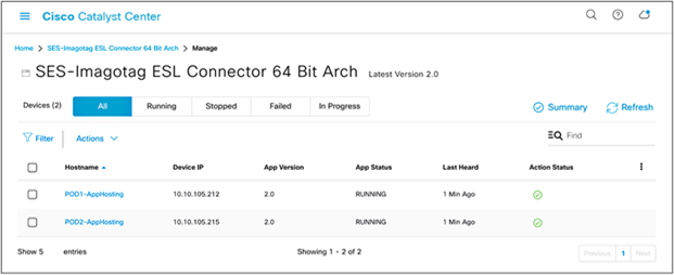
Application management page
● To manage the application deployed to the access points, click the Actions drop-down menu (Figure 53).
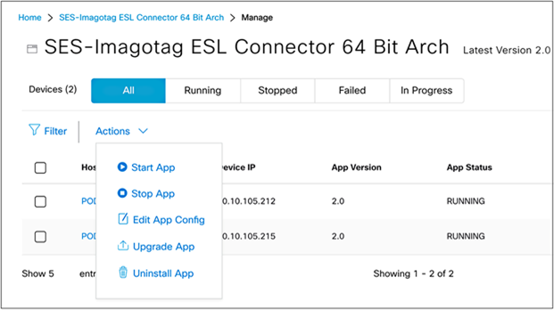
Actions drop-down menu within the application management page
Notes:
● Start App: If you stopped your application via the Stop App button, you can start it again via this button.
● Stop App: You can stop the loaded application from running. (Stopping an application does not delete or uninstall it.)
● Edit App Config: Allows you to change the configurations you’ve initially deployed the application with.
● Upgrade App: If you’ve uploaded a new version of your application in the application’s management page (Figure 39), you can click the Upgrade App button to upgrade the version running on the access points to the new version.
● Uninstall App: Choose this option to remove the application from your access points entirely.
Day 2: Monitor the IOx application (example)
At this point, your application should be successfully loaded onto your desired access points and ready for communication with your third-party management and monitoring system. This next part of the process varies from application to application, as it’s completely dependent on the design created by the third-party application developers for managing and monitoring their loaded application.
Disclaimer: The SES-imagotag ESL application discussed in this section should be used purely as a reference. If you are deploying an actual SES-imagotag ESL solution, please contact SES-imagotag for their vendor-specific deployment guide. (https://www.ses-imagotag.com/en/contact/ )
Day-2 configuration – Establishing communication between the IOx application and the management server
Description: This section provides an example of how a specific application called SES-imagotag ESL communicates with its third-party management and monitoring system.
Section goals: Understand how the SES-imagotag ESL application (one of our many supported applications) begins communicating with its third-party monitoring and management system.
Prerequisite: Understanding the SES-imagotag ESL solution and third-party management system.
Background
The SES-imagotag ESL application uses the USB port on an access point to communicate with electronic shelf labels (ESLs) through a USB BLE dongle. ESLs are used in retail stores, where they’re deployed in place of regular price tags.
The advantage of ESLs is that item prices can be updated remotely and users can easily locate any item through a mobile application. These features are accomplished by allowing the ESLs deployed throughout the store to communicate with the various SES-imagotag ESL applications loaded onto Cisco access points, which are also deployed throughout the store through a USB Bluetooth dongle. All of the deployed SES-imagotag ESL applications are managed by a central ESL management system (VUSION Cloud), allowing for an organized, end-to-end solution.
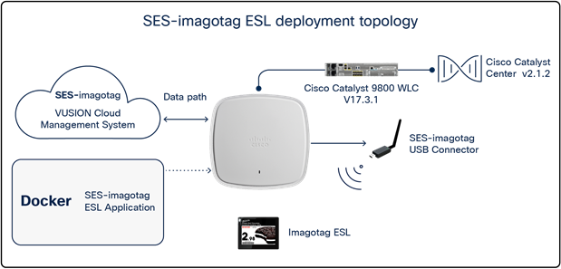
SES-imagotag ESL solution topology
Prerequisite steps:
1. Ensure that the network topology is the same as depicted in Figure 55.
2. When deploying the SES-imagotag ESL application to the access point, ensure that the following configurations have been set:
◦ APC_ADDRESS=<VUSION Cloud URL specified by SES-imagotag>
◦ APC_PORT=7354
◦ CHANNEL=<channel # you would like your SES-imagotag USB connector to broadcast>
◦ VCLOUD=false
Step 1: Add your SES-imagotag USB dongle into VUSION Cloud:
● Log in to VUSION Cloud.
● Navigate to Infrastructure, click Add, then input the Transmitter ID, which is the AP ID printed directly on the SES-imagotag USB dongle, then click Save.
a Note: If your app was deployed to the access point with the proper configurations, it should show that it is connected.
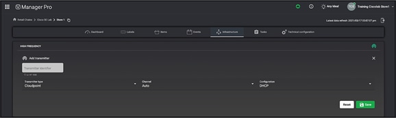
Adding the SES-imagotag USB dongle’s ID into VUSION Cloud
Step 2: Add an ESL into VUSION Cloud
● Navigate to Labels, click the up arrow on the right, and enter the label ID, which can be found directly on the ESL, then click Save.
Step 3: Associate an item to the ESL
Items are essentially the picture plus the price of the items you’re planning to advertise on the ESL screens. This step assumes that the items have already been imported into VUSION Cloud.
● Navigate to Items and copy the item code for one of the items you’d like to display on the ESL you’ve added to VUSION cloud in the previous step.
● Navigate to Labels, click the ESL you’ve added, click Matchings, add the item code into the Item code input field, then click Synchronize. After some time, VUSION Cloud will show that the ESL is successfully connected and synchronized.
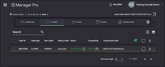
SES-imagotag ESL synchronized properly with the assigned item
Step 4: Verify on the physical ESL
● The ESL you’ve added should now also show the item you associated with it in the previous step.

Physical SES-imagotag ESL
Cisco’s Application Hosting on Catalyst Access Points provides endless possibilities to developers working in the field of IoT. This section offers some ideas of use cases as inspiration.
Use case 1: Healthcare
Background: A pandemic hit the world in 2020, caused by a virus identified as COVID-19. Due to its contagious nature, the virus has caused devastating effects throughout the globe.
Pain points: Infected individuals must be quarantined immediately to prevent further spread of the virus. The contagiousness of this virus has caused immense impacts on both patients’ well-being and medical facilities’ ability to manage operations.
How Application Hosting can address the pain points: With Application Hosting on Catalyst Access Points, you can create applications that respond to external stimuli such as voice control devices (i.e., Google Home, Amazon Echo). Your IOx application can use these received external parameters to trigger actions such as calling for a nurse, changing the temperature, adjusting the bed, etc. Such technology increases the convenience of bedridden patients and helps medical facility staff maintain maximum social distancing during COVID-19.
The figures below illustrate these examples.
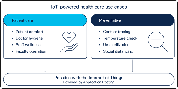
Application Hosting healthcare use cases
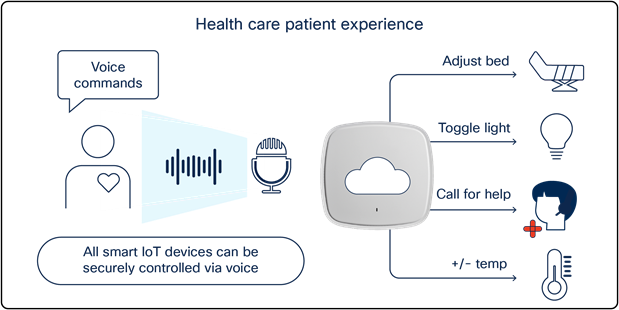
Using Application Hosting on Catalyst Access Points in a patient room
Use case 2: Building management system
Background: A sizable multiregional enterprise is looking for smarter ways to manage facilities spread through multiple countries.
Pain points: Managing these facilities and ensuring 24/7 security can be a difficult task. Often a large team of facilities managers must be onsite to ensure the safety and security of employees. Such a manual process increases personnel costs for the company and leaves security vulnerable to potential human error.
How Application Hosting can address the pain points: With Application Hosting on Catalyst Access Points, you can create applications that directly communicate with smart building management devices throughout all facilities in multiple regions at once. You can have all devices report information back to a central management server, creating a convenient command center for facilities management.
The figures below illustrate these examples.
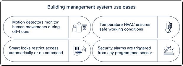
Building management system sample use cases
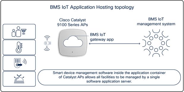
Smart devices communicating to a building management system through Catalyst access points
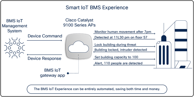
Leveraging Application Hosting to monitor multiple buildings
Use case 3: Retail stores
Background: The CEO of a large retail chain that directly competes with other e-commerce platforms such as Amazon is seeking ways to reduce overhead.
Pain points: It is difficult for in-store retailers to compete with the flexible management of an e-commerce platform. Tasks such as changing the prices of items, helping customers locate items in-store, and even showing the availability of specific items all require significantly higher overhead in a physical store than online.
How Application Hosting can address the pain points: With Application Hosting, you can create applications that directly communicate with ESLs. ESLs are used in place of standard price tags and enable in-store retailers to update item prices remotely from a computer, and to discover the availability and physical location of any item in the store through a web or mobile application.
The figures below illustrate these use cases.
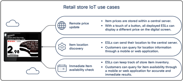
Retail store IoT use cases
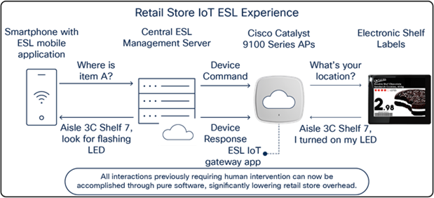
Retail store IoT ESL experience
Access point commands
● View the status of the application loaded onto the access point.
Nolan_AP#show iox applications
Total Number of Apps : 1
--------------------------
App Name : communication_daemon
App Ip : 192.168.11.2
App State : RUNNING
App Token : 0f690ed5-c341-4342-b5f3-7ab39ade8ea1
App Protocol : usb
App Grpc Connection : Down
Rx Pkts From App : 0
Tx Pkts To App : 0
Tx Pkts To Wlc : 0
Tx Data Pkts To DNASpaces : 0
Tx Cfg Resp To DNASpaces : 0
Rx KeepAlive from App : 0
Dropped Pkts : 0
App keepAlive Received On : NA
● View access point information as well as the information of any device connected via USB.
Nolan_AP#show inventory
NAME: C9130AX, DESCR: Cisco Catalyst 9130AX Series Access Point
PID: C9130AXI-B , VID: V01, SN: FJC240511KH
Entity Name : USB Module
Detected : Yes
Status : Enabled
Product ID : ea60
Vendor ID : 10c4
Manufacturer : Silicon Labs
Description : CP2102N USB to UART Bridge Controller
Serial Number : 0cd351d9f35
Max Power : 100 mA
● Verify the IOx status on the access point
Nolan_AP#show iox status
IOx Status : Enabled
CAF Status : Up
CAF Token : 9e054a32-d1ff-464e-aadd-6c5934959310
CAF Port : 8443
Cisco IOS XE WLC commands
● View the status of the USB modules connected to all joined access points.
Nolan_eWLC#show ap module summary
Output of show ap module summary:
AP Name External Module External Module PID External Module Description
-----------------------------------------------------------------------------------------------
Nolan_AP1 Enable 10c4/ea60/100 CP2102N USB to UART Bridge C
Nolan_AP2 Enable 10c4/ea60/100 CP2102N USB to UART Bridge C
● View the USB module state of each joined access point, along with other information.
● Note: Below is only a snippet of the show command output.
Nolan_eWLC #show ap config general
USB Module Type : USB Module
USB Module State : Enabled
USB Operational State : Enabled
USB Override : Disabled
● View the Application Hosting status of each joined access point.
Nolan_eWLC#show ap apphost summary
AP Name AP Mac Apphost Status CAF Port Apphost HW capable
--------------------------------------------------------------------------------------------------
SS-2027 00ee.ab18.b620 Up 8443 Yes
Axel-2036 04eb.409f.a000 Up 8443 Yes
● Configure an auxiliary-client interface (AHI) for IOx app traffic segmentation,
● Note: Ensure that this VLAN exists within your Catalyst 9800 controller.
Nolan_eWLC#config terminal
Nolan_eWLC(config)# <AP Join Profile Name>
Nolan_eWLC(config-ap-profile)# auxiliary-client interface vlan-id <VLAN ID>
● Segmentation of traffic:
When a deployed application needs to communicate to sources external to the access point's network, it can do so using a VLAN different from the access point’s management VLAN. This is accomplished with a configurable featured called the auxiliary-client interface and is enabled through WLC CLI commands.
● AP Resource allocation:
Within the access point, there are resources (CPU, memory, storage) dedicated to Application Hosting. The Application Hosting application usages will never conflict with the access point's client-serving resources and vice versa.
● Data encryption:
Cisco provides the platform infrastructure to host the IoT application; therefore, any data encryption and security on those lines between the application and the IoT devices and between the application and the application server is taken care of by each partner's specific solution.
Table 4. Application Hosting Platform Resource Specifications
| Access point |
CPU architecture |
CPU allocated (MFLOPS) |
Max memory allocated (RAM) |
Application type |
Maximum number of apps |
Maximum cores for IOx app |
Maximum storage |
USB support for IOx |
|
| C9105AXI |
ARM 32-bit |
1200 |
100 MB |
Docker |
2 |
2 |
~10 MB |
No |
|
| C9105AXW |
ARM 32-bit |
1200 |
100 MB |
Docker |
2 |
2 |
~10 MB |
Yes |
|
| C9115AX |
ARM 64-bit |
4800 |
100 MB |
Docker |
2 |
2 |
~10 MB |
Yes |
|
| C9117AX |
ARM 64-bit |
4800 |
100 MB |
Docker |
2 |
2 |
~10 MB |
Yes |
|
| C9120AX |
ARM 64-bit |
4800 |
100 MB |
Docker |
2 |
2 |
~10 MB |
Yes |
|
| C9130AX |
ARM 64-bit |
4800 |
100 MB |
Docker |
2 |
2 |
~10 MB |
Yes |
|
| C9124AX |
ARM 64-bit |
4800 |
100 MB |
Docker |
2 |
2 |
~10 MB |
No |
|
| C9136I |
ARM 64-bit |
4800 |
100 MB |
Docker |
2 |
2 |
~10 MB |
Yes |
|
| CW9162I |
ARM 64-bit |
4800 |
100 MB |
Docker |
2 |
2 |
~10 MB |
Yes |
|
| CW9164I |
ARM 64-bit |
4800 |
100 MB |
Docker |
2 |
2 |
~10 MB |
Yes |
|
| CW9166I |
ARM 64-bit |
4800 |
100 MB |
Docker |
2 |
2 |
~10 MB |
Yes |
|
| CW9166D1 |
ARM 64-bit |
4800 |
100 MB |
Docker |
2 |
2 |
~10 MB |
Yes |
|
Table 5. Application Hosting Platform PoE Capabilities
| Access point |
PoE type |
USB status and power output |
| C9105AXI |
None, no USB port |
No USB port |
| C9105AXW |
802.3at |
Y (4.5W) |
| C9115AXI/E |
802.3at |
Y (3.75W) |
| C9117AXI |
802.3bt |
Y (4.5W) |
| C9120AXI/E |
802.3at |
Y (4.5W) |
| C9130AXI/E |
802.3bt |
Y (4.5W) |
| C9124AXI/D |
None, no USB port |
No USB port |
| C9136I |
802.3bt |
Y (9W) |
| CW9162I |
802.3at |
Y (4.5W) |
| CW9164I |
802.3bt |
Y (4.5W) |
| CW9166I |
802.3bt |
Y (4.5W) |
| CW9166D1 |
802.3bt |
Y (4.5W) |
All Cisco Catalyst Center guides
● Install and upgrade guides:
Frequently asked questions
● https://developer.cisco.com/docs/app-hosting-ap/#!faqs
IOx application guides
● Application Hosting on Catalyst 9100 Access Points:
https://developer.cisco.com/app-hosting-ap/
● Application Hosting on Cisco Catalyst Access Points:
https://developer.cisco.com/docs/app-hosting-ap/
● What Is IOx?
https://developer.cisco.com/docs/iox/#!introduction-to-iox/what-is-iox
● What Is ioxclient?
https://developer.cisco.com/docs/iox/#!what-is-ioxclient
● Tutorial: Build Sample Docker Type IOx App Using Docker Toolchain:
Application Hosting video guides
● The Internet of Things – Application Hosting Overview and Use Cases
◦ https://www.youtube.com/watch?v=ZDRkKOTLat8&ab_channel=CiscoWLAN
● The Internet of Things – Application Hosting Deployment and Technical Deep Dive
◦ https://www.youtube.com/watch?v=0u3FGlRrdhU&ab_channel=CiscoWLAN