Migrating from Cisco Catalyst 6500/6800 to 9600 Series Switches
Available Languages
Bias-Free Language
The documentation set for this product strives to use bias-free language. For the purposes of this documentation set, bias-free is defined as language that does not imply discrimination based on age, disability, gender, racial identity, ethnic identity, sexual orientation, socioeconomic status, and intersectionality. Exceptions may be present in the documentation due to language that is hardcoded in the user interfaces of the product software, language used based on RFP documentation, or language that is used by a referenced third-party product. Learn more about how Cisco is using Inclusive Language.
The new Cisco® Catalyst® 9000 switching platform is the next generation in the legendary Cisco Catalyst switching family. It is designed for the new era of networking, with ASIC and software innovations to deliver an intent-based network. Within the Cisco Catalyst 9000 switching family, the Cisco Catalyst 9600 Series Switches are Cisco’s leading modular enterprise switching core and distribution platform, built for intent-based architecture, security, Internet of Things (IoT), and cloud.
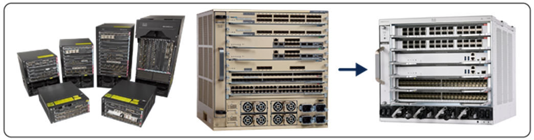
This document is intended to help network planners and engineers who are familiar with the Cisco Catalyst 6500 and 6800 Series to deploy Cisco Catalyst 9600 Series Switches in the enterprise networking environment (Figure 1).
The Cisco Catalyst 9600 Series Switches are Cisco’s leading modular core/distribution enterprise switching platform, built for security, IoT, and cloud. These switches form the foundational building block for Software-Defined Access (SD-Access), Cisco’s leading intent-based architecture. The platform provides unparalleled investment protection with a chassis architecture that is capable of supporting up to 25.6 Tbps of system bandwidth. The 9600 Series expands the end-to-end Cisco Catalyst 9000 family, further aligning our comprehensive solution with our customer carrying business and network strategies. When you need the most secure, most resilient, and most intelligent network, you need Cisco Catalyst 9600 Series Switches, the industry’s first purpose-built modular-configuration 1G, 2.5G, 5G, 10G, 25G, 40G,50G,100G and 400G line of switches for enterprise-class core and distribution layers.
The Cisco Catalyst 9600 Series offers an industry-leading supervisor engine built for secure networks, IoT applications, next-generation mobility, and cloud adoption. Supervisor Engine 1 (C9600-SUP-1) is built with the Cisco Unified Access® Data Plane 3.0 (UADP 3.0) Application-Specific Integrated Circuit (ASIC), and Supervisor Engine 2 (C9600X-SUP-2) is built with the Cisco Silicon One Q200 ASIC. Both Supervisors are ready for next-generation technologies with its programmable pipeline, microengine capabilities, and customizable allocations of Layer 2, Layer 3, forwarding, Access Control Lists (ACLs), and Quality-of-Service (QoS) entries.
The Cisco Catalyst 9600 Series Switches use a centralized architecture. All forwarding, security, and queueing is done on the supervisor, while the line cards are considered transparent, with only PHYs and control logic. The simplicity of this centralized design allows easy upgrade of features as well as additional bandwidth by upgrading just the supervisor while keeping the existing line cards. The combination of the centralized architecture and transparent line cards also provides uninterrupted supervisor switchover, which is the foundation for In-Service Software Upgrades (ISSU). With the high-capacity bandwidth provided by the Supervisor Engine 1 and Supervisor Engine 2, all ports (including 400G) are line rate with the supported configuration. The latency between all ports are less than 5 microseconds, which is more than sufficient for any time-sensitive application such as real-time video conferencing and IP telephony.
This guide lists the different considerations when migrating from the Cisco Catalyst 6500/6800 Series to the 9600 Series.
Cisco Catalyst 9606R port density
The Cisco Catalyst 9606R is a 6-slot chassis. Two middle slots are dedicated for supervisors only, and they work in redundant mode. The top and bottom two slots are for line cards. The chassis is designed to provide up to 6.4 Tbps from each of the supervisor slots to each of the line card slots. This means the system will be able to provide 32 ports of 100G at line rate per line card slot. In total, the 9606R is capable of providing either:
● 32x line rate 400G ports or
● 128x line rate 100G/40G ports or
● 192x line rate 50G/25G/10G/5G/2.5G/1G ports.
The Cisco Catalyst 9600 Supervisor Engine 1 is powered with three UADP 3.0 ASICs. The aggregated bandwidth from the three ASICs is 9.6 Tbps. The port density with Supervisor Engine 1 is as follows:
● 48x line rate 100G/40G ports or
● 192x line rate 25G/10G/5G/2.5G/1G ports
The Cisco Catalyst 9600 Supervisor Engine 2 is powered with One Cisco Silicon One ASIC. The aggregated bandwidth from ASIC is 12.8 Tbps. The port density with Supervisor Engine 2 is as follows:
● 128x line rate 100G/40G ports or
● 192x line rate 50G/25G/10G ports or
● 8x line rate 400G + 96x line rate 100/40G ports or
● 8x line rate 400G + 8x line rate 100/40G + 160 x line rate 50/25/10G ports
The Cisco Catalyst 9600 Supervisor Engine 1 is based on Cisco’s UADP 3.0 ASIC architecture and an x86 CPU architecture. The Cisco Catalyst 9600 Supervisor Engine 2 is based on Cisco Silicon One ASIC architecture and an x86 CPU architecture. Both Supervisor Engines also provide options for additional external storage, which enables the device to host containers and run third-party applications and scripts natively within the switch. Table 1 compares the hardware of the Cisco Catalyst 6500/6800 and 9600 Series.
Table 1. Hardware comparison
|
|
Cisco Catalyst 6500/6800 Series (Supervisor Engine 6T) |
Cisco Catalyst 9600 Series (Supervisor Engine 1) |
Cisco Catalyst 9600 Series (Supervisor Engine 2) |
| CPU |
Dual-core x86, 2.5 GHz |
8-core x86, 2.0 GHz |
8-core x86, 2.7 GHz |
| SDRAM |
4 GB |
16 GB |
32 GB |
| Internal flash |
4 GB |
16 GB |
16 GB |
| External storage |
4 GB USB |
480, or 960 GB* |
480, or 960 GB* |
* With Cisco certified SSD drives
Cisco Catalyst 9600 Series flexible and customized SDM templates
Unlike the supervisor on the Cisco Catalyst 6500/6800 Series, Supervisor Engines on the 9600 Series enables flexible Software Database Manager (SDM) templates for universal deployments by leveraging the ASIC’s ability to create resources to optimize table sizes for different purposes in the network. Based on how the switch is used in the network, an appropriate flexible ASIC template may be selected to configure the switch for specific features.
Cisco Catalyst 9600 Supervisor Engine 1 supports the following templates:
● Distribution: Balances resources between Layer 2 and Layer 3
● Core: Maximizes system resources for unicast and multicast routing
● NAT: Maximizes system resources for Layer 3 and Network Address Translation (NAT)
● SD-Access: Maximizes system resources to support fabric deployment ( till 17.3 1 release)
Cisco Catalyst 9600 Supervisor Engine 2 supports the following template:
● Core: Maximizes system resources for unicast and multicast routing
In the campus, the most commonly deployed design is the three-tiered design: core, distribution, and access. The core layer is based on Layer 3 IP routing and functions as a high-speed interconnection point to other network domains (data center, WAN, branch, etc.). The distribution layer traditionally consists of IP routing upstream to the core and Layer 2 switching downstream to the access layer. The access layer is purely Layer 2 and provides connectivity for the endpoints. With this design, the Core template would be the best fit for the core devices, and the Distribution template is most appropriate for the distribution devices.
The routed access design, which also can be the three-tiered design, moves the Layer 2 and Layer 3 boundaries to the access layer. In this case, the distribution layer is purely Layer 3 and doesn’t require the Layer 2 features. In this design, both the core and distribution layer devices should use the Core template.
Standard SDM templates can be used to configure system resources and optimize support for specific features. However, SDM templates are defined based on how the device is deployed in the network. A custom SDM template allows you to configure several features of the template based on your requirements and not the location of the device in the network. Both Supervisor Engine 1 and Supervisor Engine 2 support customizable SDM template for both FIB and TCAM allocations. Details information of customizable SDM template is available on C9600 datasheet.
The system default behaviors on the Cisco Catalyst 9600 Series are similar to those of the Cisco Catalyst 6500/6800 Series. For example, IP routing is enabled, the management interface is in a dedicated Virtual Routing and Forwarding (VRF) instance, and so on. However, there are also some differences, as described in this section.
Table 2. Interface default state
|
|
Cisco Catalyst 6500/6800 Series |
Cisco Catalyst 9600 Series |
| Default port type |
Layer 3 |
Layer 2 |
| Default port state |
Off (shutdown) |
On (no shutdown) |
Table 3. Port-channel default load balance
|
|
Cisco Catalyst 6500/6800 Series |
Cisco Catalyst 9600 Series |
| EtherChannel load balance |
EtherChannel Load-Balancing Configuration: src-dst-ip enhanced mpls label-ip EtherChannel Load-Balancing Addresses Used Per-Protocol: Non-IP: Source XOR Destination MAC address IPv4: Source XOR Destination IP address IPv6: Source XOR Destination IP address MPLS: Label or IP |
EtherChannel Load- Balancing Configuration: src-dst-mixed-ip-port EtherChannel Load- Balancing Addresses Used Per-Protocol: Non-IP: Source XOR Destination MAC address IPv4: Source XOR Destination IP address and TCP/UDP (layer-4) port number IPv6: Source XOR Destination IP address and TCP/UDP (layer-4) port number |
Link-status logging: The logging for link-status changes is on by default in the Cisco Catalyst 9600 Series, and the behavior can be changed per interface in the configuration. In the 6500/6800 Series, the logging for link-status changes is off by default and can be changed globally. See Table 4.
Table 4. Link-status logging comparison
|
|
Cisco Catalyst 6500/6800 Series |
Cisco Catalyst 9600 Series |
| Default |
Off for all ports |
On for all ports |
| Configuration |
Per system C6500(config)#logging event link-status global |
On (no shutdown) C9600(config)#int tw 1/0/1 C9600(config-if)#no logging event link-status |
| C6500(config)#no logging event link-status global |
C9600(config-if)#logging event link-status |
The Cisco Catalyst 9600 Series provides four slots for the power supply, compared to two slots in the 6500/6800 Series. Power supplies can operate in the following two modes:
● Combined mode: This is the default mode. All power supply modules in the system are active and sharing power.
● N+1 redundant mode: The system enters this mode if the output from the N power supply is sufficient.
For more details on power redundancy, please see the Environmental Monitoring and Power Management chapter of the System Management Configuration Guide.
The Cisco Catalyst 9600 Series uses the x86 CPU architecture, which can be used in the future to enable hosting containers and third-party applications. With the CPU architecture change, there are also changes in the ROM monitor (ROMmon).
Prompts and file system
In ROMmon, the prompt on the Cisco Catalyst 9600 Series is “rommon >” and “bootflash:” is the memory partition for local storage. On the Cisco Catalyst 6500/6800 Series, the prompt is “rommon>” and the memory partition for the local storage is “bootdisk:”. Table 5 shows outputs in ROMmon from the Cisco Catalyst 6500/6800 and 9600 Series.
Table 5. ROMmon outputs
| Cisco Catalyst 6500/6800 Series |
|||
| rommon 20 > dir bootdisk: |
|||
| File System: FAT32 |
|||
| 3 |
33554432 |
-rw- |
sea_console.dat |
| 8195 |
162870776 |
-rw- |
s6t64-ipservicesk9-mz.SPA.154-1.SY2.bin |
| 47959 |
33554432 |
-rw- |
sea_log.dat |
| 56151 |
169094712 |
-rw- |
s6t64-adventerprisek9-mz.SPA.153-1.SY2.bin |
| 97434 |
7766 |
-rw- |
startup-config.converted_vs-20171005-221623 |
| 97436 |
13820 |
-rw- |
C6807-D1-SUP6T-VSS-ECMP |
| 97440 |
14171 |
-rw- |
C6807-D1-SUP6T-VSS-VSS |
| 97444 |
14191 |
-rw- |
C6807-D1-S6T-IPV6-VSS-VSS |
| 97448 |
11151 |
-rw- |
startup-config.converted_vs-20180813-221352 |
| 97451 |
11051 |
-rw- |
startup-config.converted_vs-20180813-225913 |
| rommon 21 > |
|||
| Cisco Catalyst 9600 Series |
|||
| rommon 5 > |
dir bootflash: |
||
| Size |
Attributes Name |
||
| -------------------------------------------------------------------------------------------- |
|||
| 4096 |
-rw- |
.installer |
|
| 962 |
-rw- |
bootloader_evt_handle.log |
|
| 4096 |
-rw- |
.ssh |
|
| 4096 |
-rw- |
core |
|
| 4096 |
-rw- |
.prst_sync |
|
| 4096 |
-rw- |
.rollback_timer |
|
| 4096 |
-rw- |
gs_script |
|
| 4096 |
-rw- |
tech_support |
|
| 4096 |
-rw- |
dc_profile_dir |
|
| 324 |
-rw- |
boothelper.log |
|
| 132095 |
-rw- |
memleak.tcl |
|
| 3 |
-rw- |
.wlc_air_lic |
|
| 4096 |
-rw- |
onep |
|
| 0 |
-rw- |
rdope_out.txt |
|
| 91 |
-rw- |
rdope.log |
|
| 242 |
-rw- |
smart_overall_health.log |
|
| 35 |
-rw- |
pnp-tech-time |
|
| 71415 |
-rw- |
pnp-tech-discovery-summary |
|
| 60556 |
-rw- |
vlan.dat |
|
| 90523228 |
-rw- |
sf-linux-1017.SSA |
|
| 25124888 |
-rw- |
issg_v232_1114.zb |
|
| 4096 |
-rw- |
tan |
|
| 11359240 |
-rw- |
cat9k-cc_srdriver.16.11.01.SPA.pkg |
|
| 84354052 |
-rw- |
cat9k-espbase.16.11.01.SPA.pkg |
|
| 1676292 |
-rw- |
cat9k-guestshell.16.11.01.SPA.pkg |
|
| 466576384 |
-rw- |
cat9k-rpbase.16.11.01.SPA.pkg |
|
| 38552418 |
-rw- |
cat9k-rpboot.16.11.01.SPA.pkg |
|
| 29877252 |
-rw- |
cat9k-sipbase.16.11.01.SPA.pkg |
|
| 57259008 |
-rw- |
cat9k-sipspa.16.11.01.SPA.pkg |
|
| 19936260 |
-rw- |
cat9k-srdriver.16.11.01.SPA.pkg |
|
| 12321792 |
-rw- |
cat9k-webui.16.11.01.SPA.pkg |
|
| 9216 |
-rw- |
cat9k-wlc.16.11.01.SPA.pkg |
|
| 7612 |
-rw- |
packages.conf |
|
| 4096 |
drw- |
images |
|
| -------------------------------------------------------------------------------------------- |
|||
| rommon 6 > |
|
|
|
Boot variables
The Cisco Catalyst 6500/6800 Series uses the traditional “config-register” command in both Cisco IOS and ROMmon to control the booting behavior. The Cisco Catalyst 9600 Series uses a parallel set of commands in Cisco IOS XE Software, which creates the equivalent ROMmon variables. See Table 6 and 7.
Table 6. Boot variables
|
|
Cisco Catalyst 6500/6800 Series |
Cisco Catalyst 9600 Series |
| Cisco IOS Software |
Confreg 0x???Y Autoboot if Y!=0 |
[no] boot manual |
| ROMmon |
Confreg 0x???Y Autoboot if Y!=0 |
MANUAL_BOOT=[no | yes] |
Baud rate
Table 7. Setting the baud rate
|
|
Cisco Catalyst 6500/6800 Series |
Cisco Catalyst 9600 Series |
| Cisco IOS Software |
Confreg 0x???? or Line con 0 Speed 9600 |
Line con 0 Speed 9600 |
| ROMmon |
Confreg Use the interactive prompt to set the baud rate |
BAUD=9600 |
“Break” processing
At the beginning of the bootup process, the user can use Ctrl+C to break out of the booting process and drop the system back into ROMmon if the break sequence is enabled. See Table 8.
Table 8. “Break” processing
|
|
Cisco Catalyst 6500/6800 Series |
Cisco Catalyst 9600 Series |
| Cisco IOS Software |
Confreg 0x???? |
[no] boot enable-break |
| ROMmon |
Confreg Use the interactive prompt to set the baud rate |
ENABLE_BREAK=[no | yes] |
Ignoring the startup configuration
Table 9. Ignoring the startup configuration
|
|
Cisco Catalyst 6500/6800 Series |
Cisco Catalyst 9600 Series |
| Cisco IOS Software |
Confreg 0x8000 or 0x0040 |
C9600(config)#system ignore startupconfig C9600(config)#no system ignore startupconfig |
| ROMmon |
Confreg Use the interactive prompt to enable/ disable ignore startup configuration |
SWITCH_IGNORE_STARTUP_ CFG=1 |
Interface reference
The Cisco Catalyst 6500/6800 Series has two levels of interface numbering:
interface <Type><Slot#>/<Port#>.
The 9600 Series has three levels:
interface <Type><Slot#>/<Bay#>/<Port#>.
As of Release 16.12.1, the bay number is unused and is always 0. For example, FortyGigabit Ethernet port 1 on slot 1 is referenced as Fo1/1 in the 6500/6800 Series and as Fo1/0/1 in the 9600 Series. See Table 10.
Table 10. Interface numbering
|
|
Cisco Catalyst 6500/6800 Series |
Cisco Catalyst 9600 Series |
| TenGigabit Ethernet |
TenGigabitEthernet1/1 |
Te1/0/1 |
| FortyGigabit Ethernet |
FortyGigabitEthernet5/1 |
Fo5/0/1 |
Management interface
The management interface on the Cisco Catalyst 9600 Series can be a copper Gigabit Ethernet or fiber 10 Gigabit Ethernet interface. The Cisco Catalyst 6500/6800 Supervisor Engine 6T provides copper or fiber Gigabit Ethernet. The management port on both platforms has its own VRF for separation of management traffic from normal data traffic. However, the name of the VRF for the management port is different between the 9600 Series and 6500/6800 Series. Note also that the names of the VRFs are case sensitive. Table 11 lists the management port differences between the two platforms.
Table 11. Management interfaces and VRF names
|
|
Cisco Catalyst 6500/6800 Series |
Cisco Catalyst 9600 Series |
| Interface |
Mgmt0 |
GigabitEthernet0/0 TenGigabitEther0/1 |
| VRF |
management |
Mgmt-vrf |
For details on the software features supported on the Cisco Catalyst 9600 Series, please use the feature navigator on Cisco.com. Some of the features behave differently on the 9600 Series compared to the 6500/6800 Series. Following are some of these differences.
System Maximum Transmission Unit (MTU)
System MTU is a Layer 2 MTU. On the Cisco Catalyst 9600 Series, the global command “system mtu <1500-9216>” changes the Layer 2 MTU on all the interfaces within the system. There is no support for an interface-level command to set the MTU for individual interfaces as of Cisco IOS XE Software Release 16.12.1. On the Cisco Catalyst 6500/6800 Series, the global command “system jumbo <1500-9216>” sets the global baby giant MTU for all interfaces. The default system jumbo MTU is 9216. The 6500/6800 Series also supports a per-interface MTU. The per-interface MTU command takes precedence. See Table 12.
Table 12. System MTU
|
|
Cisco Catalyst 6500/6800 Series |
Cisco Catalyst 9600 Series |
| “system jumbomtu <>” |
Changes Layer 2 MTU on all interfaces |
N/A |
| “system mtu” |
N/A |
Changes Layer 2 MTU on all interfaces |
| System jumbomtu/ MTU value |
1500 to 9216 |
1500 to 9216 |
| Interface-level MTU (layer 2) |
● Range “1500 to 9216”
● Takes precedence over system MTU
|
● Range “1500 to 9216”
● Takes precedence over system MTU
|
StackWise virtual
The Cisco Catalyst 6500/6800 Series supports a Virtual Switching System (VSS) that combines two physical switches into a single logical switch. The equivalent functionality on the 9600 Series is Cisco StackWise® Virtual. StackWise Virtual and VSS have the same functionalities but different implementations.
Port-channel load balancing
The Cisco Catalyst 9600 Series provides additional combinations of different header fields as input for port-channel load balancing. Table 13 lists the supported load-balancing methods for the 6500/6800 and 9600 Series.
Table 13. Port-channel load balancing
| Cisco Catalyst 6500/6800 Series |
Cisco Catalyst 9600 Series |
||
| C6500E: |
C9600: |
||
| dst-ip |
Dst IP Addr |
dst-ip |
Dst IP Addr |
| dst-mac |
Dst Mac Addr |
dst-mac |
Dst Mac Addr |
| dst-mixed-ip-port Port |
Dst IP Addr and TCP/UDP |
dst-mixed-ip-port Port |
Dst IP Addr and TCP/ UDP |
| dst-port |
Dst TCP/UDP Port |
dst-port |
Dst TCP/UDP Port |
| mpls packets |
Load Balancing for MPLS |
|
|
|
|
extended |
Load Balance Methods |
|
| src-dst-ip |
Src XOR Dst IP Addr |
src-dst-ip |
Src XOR Dst IP Addr |
| src-dst-mac |
Src XOR Dst Mac Addr |
src-dst-mac |
Src XOR Dst Mac Addr |
| src-dst-mixed-ip-port TCP/UDP Port |
Src XOR Dst IP Addr and |
src-dst-mixed-ip-port TCP/UDP Port |
Src XOR Dst IP Addr and |
| src-dst-port |
Src XOR Dst TCP/UDP Port |
src-dst-port |
Src XOR Dst TCP/UDP Port |
| src-ip |
Src IP Addr |
src-ip |
Src IP Addr |
| src-mac |
Src Mac Addr |
src-mac |
Src Mac Addr |
| src-mixed-ip-port Port |
Src IP Addr and TCP/UDP |
src-mixed-ip-port Port |
Src IP Addr and TCP/ UDP |
| src-port |
Src TCP/UDP Port |
src-port |
Src TCP/UDP Port |
| vlan-dst-ip |
Vlan, Dst IP Addr |
vlan-dst-ip |
Vlan, Dst IP Addr |
| vlan-dst-mixed-ip-port TCP/UDP Port |
Vlan, Dst IP Addr and |
vlan-dst-mixed-ip-port TCP/UDP Port |
Vlan, Dst IP Addr and |
| vlan-src-dst-ip |
Vlan, Src XOR Dst IP Addr |
vlan-src-dst-ip |
Vlan, Src XOR Dst IP Addr |
| vlan-src-dst-mixedip-port and TCP/UDP Port |
Vlan, Src XOR Dst IP Addr |
vlan-src-dst-mixedip-port and TCP/UDP Port |
Vlan, Src XOR Dst IP Addr |
| vlan-src-ip |
Vlan, Src IP Addr |
vlan-src-ip |
Vlan, Src IP Addr |
| vlan-src-mixed-ip-port TCP/UDP Port |
Vlan, Src IP Addr and |
vlan-src-mixed-ip-port TCP/UDP Port |
Vlan, Src IP Addr and |
The “extended” option on the Cisco Catalyst 9600 Series provides additional combinations of different fields:
C96000(config)#port-channel load-balance extended ?
dst-ip Dest IP
dst-mac Dest MAC
dst-port Dest Port
ipv6-label IPV6 Flow Label
l3-proto L3 Protocol
src-ip Src IP
src-mac Src MAC
src-port Src Port
<cr> <cr>
C96000(config)#
Port-channel services
Table 14. Port-channel services
| Cisco Catalyst 6500/6800 Series |
Cisco Catalyst 9600 Series |
| QoS policies are configured on the port-channel interfaces |
QoS policies are configured on the individual port-channel member ports |
| Port ACLs (PACLs) are configured on the port-channel interfaces |
PACLs are configured on the individual port-channel member ports |
Virtualization: VNET
The Cisco Catalyst 6500 Series supports the Easy Virtual Network (EVN) feature, which uses VNET. This feature is no longer available on the Cisco Catalyst 9000 switch family. The alternative is to configure VRF-Lite with subinterfaces, which are supported on the 9600 Series switches.
Host tracking feature
The Cisco Catalyst 6500/6800 Series supports IP Device Tracking (IPDT) for keeping track of connected hosts (association of MAC and IP addresses). In the Cisco Catalyst 9600 Series with the latest Cisco IOS XE release, the new Switch Integrated Security Features (SISF)-based IPDT feature acts as a container policy that enables snooping and device-tracking features available with First Hop Security (FHS) in both IPv4 and IPv6, using IP-agnostic Command-Line Interface (CLI) commands. See Appendix A for more information on migrating from the IPDT CLI configuration to the new SISF-based device-tracking CLI configuration.
Access control lists
Object group ACLs: Both the Cisco Catalyst 6500/6800 Series and 9600 Series support object group ACLs. There are, however, syntax differences. Table 15 shows some examples of object group ACLs with source and destination port groups.
Table 15. Object group ACLs
| Object group ACL features |
Cisco Catalyst 6500/6800 Series |
Cisco Catalyst 9600 Series |
|
| Object group ACL with source port group |
object-group ip address g1 host 10.20.20.1 host 10.20.21.1 object-group ip port p1 gt 100 lt 200 ip access-list extended test1 permit tcp host 1.1.1.1 port-group p1 adrgroup g1 |
object-group network g1 host 10.20.20.1 host 10.20.21.1 object-group service p1 tcp source gt 100 tcp source lt 200 ip access-list extended test1 permit object-group p1 host 1.1.1.1 object-group g1 |
|
| Object group ACL with destination port group |
object-group ip address g2 host 10.30.20.1 host 10.30.21.1 object-group ip port p2 gt 300 lt 400 ip access-list extended test2 permit tcp host 1.1.1.1 addrgroup g2 port-group p2 |
object-group network g2 host 10.30.20.1 host 10.30.21.1 object-group service p2 tcp gt 300 tcp lt 400 ip access-list extended test2 permit object-group p2 host 1.1.1.1 object-group g2 |
|
| Object group ACL with source and destination port groups |
object-group ip address g1 host 10.20.20.1 host 10.20.21.1 object-group ip port p1 gt 100 lt 200 object-group ip address g2 host 10.30.20.1 host 10.30.21.1 object-group ip port p2 gt 300 lt 400 ip access-list extended test3 permit tcp addrgroupt g1 portgroup p1 addrgroup g2 portgroup p2 |
object-group network g1 host 10.20.20.1 host 10.20.21.1 object-group service p3 tcp source gt 100 gt 300 tcp source gt 100 lt 400 tcp source lt 200 gt 300 tcp source lt 200 lt 400 object-group network g2 host 10.30.20.1 host 10.30.21.1 ip access-list extended test3 permit object-group p3 object-group g1 object-group g2 |
|
| Object group ACL with “established” keyword |
object-group ip address g4 10.22.33.0 255.255.255.0 10.33.44.0 255.255.255.0 object-group ip port p4 eq 500 eq 600 ip access-list extended test4 permit tcp addrgroup g4 portgroup p4 10.30.40.0 0.0.0.255 established |
object-group network g4 10.22.33.0 255.255.255.0 10.33.44.0 255.255.255.0 ip access-list extended test4 permit tcp object-group g4 eq 500 10.30.40.0 0.0.0.255 established permit tcp object-group g4 eq 600 10.30.40.0 0.0.0.255 established |
|
Note: To view the expanded ACL for object group ACLs, enable “service internal” and use the command “show ip access-list <list_name> expand.”
Access group mode: When PACLs are applied to the physical port, VLAN ACLs (VACLs) are applied to the VLAN, and Router ACLs (RACLs) are applied to the Switch Virtual Interface (SVI), the Cisco Catalyst 6000 Series offers options to merge all three ACLs with the option “merge mode” or to ignore VACLs and RACLs with the option “prefer port mode.” With the 9600 Series, the ACLs will always be applied in the following order: PACL, VACL, and then RACL.
TCAM exhaustion
In the Cisco Catalyst 6000 Series, once the Access Control Entries (ACE) exceed the maximum free available Ternary Content Addressable Memory (TCAM) spaces, ACL reduction will occur, and any traffic hitting the overflowed ACL will be software switched.
In the Cisco Catalyst 9000 family, the overflowed ACL will not be programmed and will have a default of “deny all” for the overflowed ACL.
Flexible NetFlow
Both the Cisco Catalyst 9600 Series and 6500/6800 Series support Flexible NetFlow. Beside the scalability differences, there are a few configuration differences. They are listed in Table 16.
Table 16. Flexible NetFlow differences
|
|
Cisco Catalyst 6500/6800 Series |
Cisco Catalyst 9600 Series |
| Timestamp |
Use system uptime |
Use absolute time [0 is at time 00:00:00 January 1, 1970] |
| NetFlow on port channel |
Configuration under port channel |
Configuration under L3 port channel and member of L2/L3 port channel |
| Bridged traffic |
Apply the flow monitor to the Layer 2 interface with keyword “layer2-switched” |
Apply the flow monitor to a VLAN |
| NetFlow on tunnel |
Supported |
Not supported |
| NetFlow collect options: collect routing next-hop address ipv4 collect ipv4 source prefix collect ipv4 source mask collect ipv4 destination mask collect flow sampler |
Supported |
Supported |
Embedded Logic Analyzer Module (ELAM)
The Cisco Catalyst 6500/6800 Series supports the ELAM feature, which captures packets in real time on the switch without disruptions to performance. The more comprehensive feature on the Cisco Catalyst 9600 Series is Wireshark.
The following are the differences between the 6500/6800 Series ELAM and the 9600 Series Wireshark:
● The ELAM feature configures and displays commands through show commands only. In Wireshark capture, configuration is through the monitor-level CLI and display is though show commands.
● ELAM is capable of packet capture at the ASIC level, whereas packet capture occurs at the interface level with Wireshark.
● ELAM captures only the first packet that hits the switch that matches the configuration. Wireshark is capable of capturing packets over a duration.
● Wireshark can capture both data plane and control plane packets.
Switched Port Analyzer (SPAN) filter
Both the Cisco Catalyst 6500/6800 and 9600 Series support SPAN filters. The 6500/6800 Series supports a filter option of “good/bad,” which isn’t supported on the 9600 Series.
Quality of Service (QoS)
The ASICs that power the Cisco Catalyst 65006800 and 9600 Series are different, so there are some differences in QoS behaviors, as described below.
Hardware rate limiters
On the Cisco Catalyst 6500/6800 Series, the “platform rate-limit” command enables rate limiting in hardware. All rate limiting or policing is done in hardware with the 9600 Series, so this command is not needed.
Control plane policing
Control Plane Policing (CoPP) is enabled on the Cisco Catalyst 9600 Series, with default policing rates for different classes of traffic. These policing rates are optimized for a typical campus environment.
The policing rates can be changed or disabled to meet the requirements of different application environments. On the Cisco Catalyst 6500/6800 Series with Supervisor Engine 2T or 6T, CoPP is also enabled by default and can be disabled. The 6500/6800 Series also allows class maps under CoPP to be added, modified, or removed. Table 17 lists the differences between the two platforms.
Table 17. CoPP differences
|
|
Cisco Catalyst 6500/6800 Series |
Cisco Catalyst 9600 Series |
| Default |
Enabled (can be disabled) |
Enabled (can’t be disabled, but policing rates can be modified) |
| CoPP class map |
Can be added, modified, or removed |
System predefined |
| Policing rate |
Can be modified |
Can be modified |
Table 18 lists the buffer differences between the Cisco Catalyst 9600 Supervisor Engine 1, Supervisor Engine 1 and the Cisco Catalyst 6500 Supervisor Engine 6T.
Table 18. Buffers
|
|
Cisco Catalyst 6500 Supervisor Engine 2T |
Cisco Catalyst 9600 Supervisor Engine 1 |
Cisco Catalyst 9600 Supervisor Engine 2 |
| Buffer |
Varies depending on the line card |
3x36 MB |
80 MB (Shared Memory System) + 8 GB (High Bandwidth Memory) |
| Buffer Sharing |
Buffers are dedicated per port |
Buffer sharing is within the ASIC; there are 3 ASICs in Supervisor Engine 1 |
Buffer sharing is within the ASIC. |
Cisco Catalyst 6000 Series platform-specific commands
Table 19 lists commands that are specific to the Cisco Catalyst 6000 Series and are not available on the 9600 Series.
Table 19. Cisco Catalyst 6500/6800 Series platform-specific commands
| Cisco Catalyst 6500/6800 Series |
Cisco Catalyst 9600 Series |
| mls <…> |
Not applicable; the 9600 Series provides hardware-enabled feature by default |
| Auto qos default |
Auto qos global compact |
| diagnostic fpga soft-error recover conservative |
Not applicable |
| ntp update-calendar |
clock calendar-valid |
| ip device tracking |
Please see Appendix A |
| Platform ip cef load-sharing full |
Not applicable |
| Flow hardware usage notify <…> |
Not applicable |
| Flow hardware usage notify <…> |
Not applicable |
| Vlan internal allocation policy asending |
Not applicable |
| Vlan access-log ratelimit <…> |
Not applicable |
| Ip domain-name |
Ip domain name |
| Ip domain-lookup |
Ip domain lookup |
The Cisco Catalyst 9600 Series Switches are Cisco’s leading modular enterprise switching core and distribution platforms. They are the new generation of the core and distribution platform and provide many additional capabilities, making them well suited for enterprises looking to migrate from their existing Cisco Catalyst 6500/6800 Series deployment.
If your device has no legacy IP device tracking or IPv6 snooping configurations, you can use only the new SISF-based device-tracking commands for all your future configurations. The legacy IPDT commands and IPv6 snooping commands are not available. For details on SISF configuration, please refer to the configuration guide.
IPDT, IPv6 snooping, and device-tracking CLI compatibility
Table 20 displays the new SISF-based device-tracking commands and the corresponding IPDT and IPv6 snooping commands.
Table 20. Device-tracking and corresponding IPDT and IPv6 snooping commands
| IP Device Tracking (IPDT) |
IPv6 snooping |
SISF-based device tracking |
| IP device tracking probe count |
Not supported |
Not supported |
| IP device tracking probe delay |
IPv6 neighbor binding reachable-lifetime |
Device-tracking policy reachable-lifetime |
| IP device tracking probe interval |
IPv6 snooping tracking retry-interval |
Device-tracking policy retry-interval |
| IP device tracking probe use-svi |
Accepted and interpreted as IP device tracking probe auto-source override |
Accepted and interpreted as IP device tracking auto-source override |
| IP device tracking probe auto-source fallback |
Not supported |
Not supported |
| IP device tracking probe auto-source override |
Not supported |
Not supported |
| IP device tracking tracebuffer |
Not supported |
Not supported |
| IP device tracking maximum |
IPv6 snooping policy <name> limit |
Device-tracking snooping policy <name> limit |
| IP device tracking probe count |
Not supported |
Not supported |
| IP device tracking probe interval |
Not supported |
Not supported |
| Clear ip device tracking all |
Not supported |
Not supported |