Cisco UCS X210c M6 Compute Node Disk I/O Characterization White Paper
Available Languages
Bias-Free Language
The documentation set for this product strives to use bias-free language. For the purposes of this documentation set, bias-free is defined as language that does not imply discrimination based on age, disability, gender, racial identity, ethnic identity, sexual orientation, socioeconomic status, and intersectionality. Exceptions may be present in the documentation due to language that is hardcoded in the user interfaces of the product software, language used based on RFP documentation, or language that is used by a referenced third-party product. Learn more about how Cisco is using Inclusive Language.
The Cisco UCS X210c M6 compute node is the first computing device to integrate into the Cisco UCS X-Series Modular System. Up to eight compute nodes can reside in the 7-Rack-Unit (7RU) Cisco UCS X9508 Chassis, offering one of the highest densities of compute, I/O, and storage per rack unit in the industry.
This document summarizes the I/O performance characteristics of the Cisco UCS X210c M6 compute node using Non-Volatile Memory express (NVMe) and SAS Solid-State Disks (SSDs). The goal of this document is to help customers make well-informed decisions so that they can choose the right drives to meet their I/O workload needs.
Performance data was obtained using the FIO measurement tool, with analysis based on the number of I/O operations per second (IOPS) for random I/O workloads and Megabytes-Per-Second (MBps) throughput for sequential I/O workloads. From this analysis, specific recommendations are made for storage configuration parameters.
The Cisco UCS X-Series Modular System simplifies your data center, adapting to the unpredictable needs of modern applications while also providing for traditional scale-out and enterprise workloads. It reduces the number of server types to maintain, helping to improve operational efficiency and agility as it helps reduce complexity. Powered by the Cisco Intersight cloud operations platform, it shifts your thinking from administrative details to business outcomes with hybrid cloud infrastructure that is assembled from the cloud, shaped to your workloads, and continuously optimized.
Cisco UCS X-Series Modular System
The Cisco UCS X-Series Modular System begins with the Cisco UCS X9508 Chassis (Figure 1), engineered to be adaptable and future ready. The X-Series is a standards-based open system designed to be deployed and automated quickly in a hybrid cloud environment.
With a midplane-free design, I/O connectivity for the X9508 Chassis is accomplished with front-loading vertically oriented computing nodes that intersect with horizontally oriented I/O connectivity modules in the rear of the chassis. A unified Ethernet fabric is supplied with the Cisco UCS 9108 Intelligent Fabric Modules. In the future, Cisco UCS X-Fabric Technology interconnects will supply other industry-standard protocols as standards emerge. Interconnections can easily be updated with new modules.
Cisco UCS X-Series is powered by Cisco Intersight, making it simple to deploy and manage at scale
The Cisco UCS X9508 Chassis provides these features and benefits:
● The Seven-Rack-Unit (7RU) chassis has eight front-facing flexible slots. These can house a combination of computing nodes and a pool of future I/O resources, which may include Graphics Processing Unit (GPU) accelerators, disk storage, and nonvolatile memory.
● Two Cisco UCS 9108 Intelligent Fabric Modules at the top of the chassis connect the chassis to upstream Cisco UCS 6400 Series Fabric Interconnects. Each Intelligent Fabric Module offers these features:
◦ The module provides up to 100 Gbps of unified fabric connectivity per computing node.
◦ The module provides eight 25-Gbps Small Form-Factor Pluggable 28 (SFP28) uplink ports.
◦ The unified fabric carries management traffic to the Cisco Intersight cloud-operations platform, FCoE traffic, and production Ethernet traffic to the fabric interconnects.
● At the bottom of the chassis are slots ready to house future I/O modules that can flexibly connect the computing modules with I/O devices. Cisco calls this connectivity Cisco UCS X-Fabric technology, because “X” is commonly used as a variable, signifying a system that can evolve with new technology developments.
● Six 2800-watt (W) Power Supply Units (PSUs) provide 54 volts (V) of power to the chassis with N, N+1, and N+N redundancy. A higher voltage allows efficient power delivery with less copper wiring needed and reduced power loss.
● Efficient, 4 x 100–mm, dual counter-rotating fans deliver industry-leading airflow and power efficiency. Optimized thermal algorithms enable different cooling modes to best support the network environment. Cooling is modular, so future enhancements can potentially handle open- or closed- loop liquid cooling to support even higher-power processors.
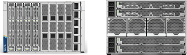
Cisco UCS 9508 X-Series Chassis, front (left) and back (right)
Since Cisco first delivered the Cisco Unified Computing System in 2009, our goal has been to simplify the data center. We pulled management out of servers and into the network. We simplified multiple networks into a single unified fabric. And we eliminated network layers in favor of a flat topology wrapped into a single unified system. With the Cisco UCS X-Series Modular System, the simplicity is extended even further:
● Simplify with cloud-operated infrastructure. We move management from the network into the cloud so that you can respond at the speed and scale of your business and manage all your infrastructure.
You can shape Cisco UCS X-Series Modular System resources to workload requirements with the Cisco Intersight cloud-operations platform. You can integrate third-party devices, including storage from NetApp, Pure Storage, and Hitachi. In addition, you gain intelligent visualization, optimization, and orchestration for all your applications and infrastructure.
● Simplify with an adaptable system designed for modern applications. Today’s cloud-native, hybrid applications are inherently unpredictable. They are deployed and redeployed as part of an iterative DevOps practice. Requirements change often, and you need a system that doesn’t lock you into one set of resources when you find that you need a different set. For hybrid applications, and for a range of traditional data center applications, you can consolidate your resources on a single platform that combines the density and efficiency of blade servers with the expandability of rack servers. The result is better performance, automation, and efficiency.
● Simplify with a system engineered for the future. Embrace emerging technology and reduce risk with a modular system designed to support future generations of processors, storage, nonvolatile memory, accelerators, and interconnects. Gone is the need to purchase, configure, maintain, power, and cool discrete management modules and servers. Cloud-based management is kept up-to-date automatically with a constant stream of new capabilities delivered by the Cisco Intersight SaaS model.
● Support a broader range of workloads. A single server type supporting a broader range of workloads means fewer different products to support, reduced training costs, and increased flexibility.
Cisco UCS X210c Series Servers
The Cisco UCS X-Series Modular System simplifies your data center, adapting to the unpredictable needs of modern applications while also accommodating traditional scale-out and enterprise workloads. It reduces the number of server types that you need to maintain, helping to improve operational efficiency and agility by reducing complexity. Powered by the Cisco Intersight cloud operations platform, it shifts your thinking from administrative details to business outcomes with hybrid cloud infrastructure that is assembled from the cloud, shaped to your workloads, and continuously optimized.
The Cisco UCS X210c M6 Compute Node is the first computing device integrated into the Cisco UCS X- Series Modular System. Up to eight computing nodes can reside in the 7RU Cisco UCS X9508 Chassis, offering one of the highest densities of computing, I/O, and storage resources per rack unit in the industry. The Cisco UCS X210c harnesses the power of the latest Third-Generation (3rd Gen) Intel Xeon Scalable processors (Ice Lake). It includes the following features:
● CPU: Install up to two 3rd Gen Intel Xeon Scalable processors with up to 40 cores per processor and 1.5 MB of Level 3 cache per core.
● Memory: Install up to thirty-two 256-GB DDR4 3200-MHz DIMMs for up to 8 TB of main memory. Configuring up to sixteen 512-GB Intel Optane persistent-memory DIMMs can yield up to 12 TB of memory.
● Storage: Install up to six hot-pluggable Solid-State Disks (SSDs) or Non-Volatile Memory Express (NVMe) 2.5-inch drives with a choice of enterprise-class RAID or pass-through controllers with four lanes each of PCIe Gen 4 connectivity and up to two M.2 SATA drives for flexible boot and local storage capabilities.
● Modular LAN-on-motherboard (mLOM) Virtual Interface Card (VIC): The Cisco UCS VIC 14425 occupies the server's mLOM slot, enabling up to 50-Gbps unified fabric connectivity to each of the chassis Intelligent Fabric Modules for 100-Gbps connectivity per server.
● Optional mezzanine VIC: The Cisco UCS VIC 14825 can occupy the server's mezzanine slot at the bottom rear of the chassis. This card's I/O connectors link to Cisco UCS X-Fabric technology that is planned for future I/O expansion. An included bridge card extends this VIC's two 50-Gbps network connections through Intelligent Fabric Module connectors, bringing the total bandwidth to 100 Gbps per fabric (for a total of 200 Gbps per server).
● Security: The server supports an optional Trusted Platform Module (TPM). Additional features include a secure boot field-programmable gateway (FPGA) and Anti-Counterfeit Technology 2 (ACT2) provisions
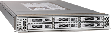
Front view of X210c compute node
A specifications sheet for the X210c M6 compute node is available at: https://www.cisco.com/c/dam/en/us/products/collateral/servers-unified-computing/ucs-x-series-modular-system/x210c-specsheet.pdf
For the NVMe I/O performance characterization tests, performance was evaluated using NVMe SSDs for random and sequential access patterns with Cisco UCS X210c M6 compute node servers. These servers support up to 6 NVMe SSDs connected directly by PCIe Gen4 x4 lanes to the CPU. An Intel D7-P5600 6.4 TB NVMe SSD is configured on all eight blades.
For the SSD I/O performance characterization tests, compute node was configured with RAID controller for managing SAS/SATA drives. Performance was evaluated using SAS SSDs for random and sequential access patterns with configurations of RAID 0, 5, and 10 virtual drives to achieve maximum performance with six SAS SSDs. 960 GB 12G SAS SSD is configured on all eight blades.
The selection of this NVMe and SAS SSD drive for disk I/O characterization was made based on the drive specifications because they are high-performance drives from the list supported by x210c servers at the time of this paper’s publication.
The performance-tested solution used the following:
● Cisco UCS X210c M6 Compute Node
● Cisco UCS X9508 Chassis
● Intel D7-P5600 6.4 TB NVMe SSD
● 960 GB Enterprise value 12G SAS SSD
This section provides an overview of the specific access patterns used in the performance tests.
Tables 1 and 2 list the I/O mix ratios chosen for the sequential access and random access patterns, respectively.
Table 1. I/O mix ratio for sequential access pattern
| I/O mode |
I/O mix ratio (read:write) |
|
| Sequential |
100:0 |
0:100 |
| RAID 0, 10 |
RAID 0, 10 |
|
| NVMe |
NVMe |
|
Table 2. I/O mix ratio for random access pattern
| I/O mode |
I/O mix ratio (read:write) |
|
|||
| Random |
100:0 |
0:100 |
70:30 |
50:50 |
|
| RAID 0 |
RAID 0 |
RAID 0, 5 |
RAID 5 |
||
| NVMe |
NVMe |
NVMe |
|
||
Table 3. Recommended virtual drive configuration for SAS/SATA SSDs
| Access pattern |
RAID level |
Strip size |
Disk cache policy |
I/O cache policy |
Read policy |
Write policy |
| Random I/O |
RAID 0 |
64 KB |
Unchanged |
Direct |
No read ahead |
Write through |
| Random I/O |
RAID 5 |
64 KB |
Unchanged |
Direct |
No read ahead |
Write through |
| Sequential I/O |
RAID 0 |
64 KB |
Unchanged |
Direct |
No read ahead |
Write through |
| Sequential I/O |
RAID 10 |
64 KB |
Unchanged |
Direct |
No read ahead |
Write through |
Note: Disk cache policy is set as “Unchanged” as it cannot be modified for VDs created using SSD.
The test configuration was as follows:
● NVMe - 6 x D7-P5600 NVMe SFF SSDs on each X210c M6 compute node
● SAS SSD on each X210c M6 compute node
◦ 6 RAID 0 virtual drives were created with 6 disks.
◦ 1 RAID 5 virtual drive was created with 6 disks.
◦ 1 RAID 10 virtual drive was created with 4 disks.
◦ RAID configuration was tested with Cisco UCSX-X210C-RAIDF storage controller
● 8 x X210c M6 compute node blades on Cisco UCS X9508 chassis
● Random workload tests were performed using 4 and 8 KB block sizes for both SAS and NVMe SSDs
● Sequential workload tests were performed using 256 KB and 1 MB block size for both SAS and NVMe SSDs
Performance data was obtained using the fio measurement tool, with analysis based on the IOPS rate for random I/O workloads and on MBps throughput for sequential I/O workloads. From this analysis, specific recommendations can be made for storage configuration parameters.
The server specifications and BIOS settings used in these performance characterization tests and fio settings are detailed in the appendix, Test environment.
The I/O performance test results capture the maximum read IOPS rate and bandwidth achieved with the NVMe SSDs within the acceptable response time (average latency). Latency is the time taken to complete a single I/O request from the viewpoint of the application.
NVMe SSD (6.4 TB High Perf High Endurance) performance for 8 x X210c Compute nodes
UCS X9508 chassis is configured with 8 x X210c Compute Node blades. Each blade is populated with 6 x P5600 6.4 TB NVMe SSDs and there are total 48 NVMe SSDs configured on eight blades. Graphs below show the scaling of performance from one blade to eight blades with tests were run in parallel for Random and Sequential I/O patterns.
Random read (100%)
Figure 3 shows the performance of the NVMe SSDs under test for X210c M6 compute node blades with UCS X9508 chassis with a 100-percent random read access pattern with both 4 KB and 8 KB block sizes. The graph shows the performance of ~6M IOPS with average latency of 240 microseconds when six NVMe SSDs populated on a single X210c M6 compute node for 4 KB block size.
The aggregate performance of ~48M IOPS with average latency of 240 microseconds is achieved with all eight X210c M6 compute nodes in the chassis. This demonstrates a linear scaling of IOPS without any variation of latency. Similar trend is observed for 8 KB block size as can be seen from the below graph.
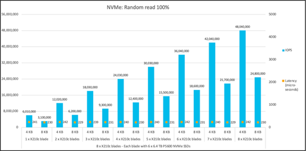
Random read 100%
Random write (100%)
Figure 4 shows the performance of the NVMe SSDs under test for 8 x X210c M6 compute node blades with UCS X9508 chassis with a 100-percent random write access pattern with 4 KB and 8 KB block sizes. The graph shows the performance of ~1.6M IOPS with latency of 95 microseconds with six NVMe SSDs on single X210c M6 compute node.
The aggregate performance of ~12.8M IOPS with latency of 95 microseconds is achieved with all eight X210c M6 compute nodes in the chassis. Again, like Random read results, this results also follows linear IOPS scaling without any variation of latency. Similar trend is observed for 8 KB block size as can be seen from the below graph.
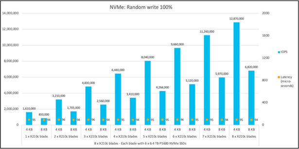
Random write 100%
Random read:write (70R:30W)
Figure 5 shows the performance of the NVMe SSDs under test for 8 x X210c M6 compute node blades with UCS X9508 chassis with a 70:30-percent random read:write access pattern. The graph shows the performance of ~3.1M IOPS (combined IOPS of Read and Write) with read latency of 230 microseconds and write latency of 98 microseconds with six NVMe SSDs on single X210c M6 compute node for a 4 KB block size.
The aggregate performance of ~24M IOPS with read latency of 232 microseconds and write latency of 100 microseconds is achieved with total of forty-eight NVMe SSDs on 8 x X210c M6 compute node blades for a 4 KB block size, maintaining linearity.

Random read:write 70:30%
Sequential read (100%)
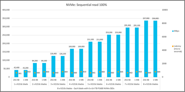
Figure 6 shows the performance of the NVMe SSDs under test for 8 x X210c M6 compute node blades with UCS X9508 chassis with a 100-percent sequential read access pattern. The graph shows the performance of ~42,000 MBps with latency of 661 microseconds with six NVMe SSDs on single X210c M6 compute node for a 256 KB block size.
The aggregate performance of ~337,000 MBps with latency of 660 microseconds is achieved with total of forty-eight NVMe SSDs for a 256 KB block size. Similar linear trend (scaling from one blade to eight blades) is observed for 1 MB block size as well.
Sequential read 100%
Sequential write (100%)
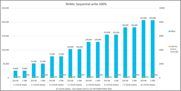
Figure 7 shows the performance of the NVMe SSDs under test for 8 x X210c M6 compute node blades with UCS X9508 chassis with a 100-percent sequential write access pattern. The graph shows the performance of ~25,800 MBps with latency of 152 microseconds with six NVMe SSDs on single X210c M6 compute node for a 256 KB block size.
The aggregate performance of ~207,000 MBps with latency of 151 microseconds is achieved with total of forty-eight NVMe SSDs on 8 x X210c M6 compute node blades for a 256 KB block size. Similar linear trend (scaling from one blade to eight blades) is observed for 1 MB block size as well.
Sequential write 100%
Performance data was obtained using the fio measurement tool, with analysis based on the IOPS rate for random I/O workloads and on MBps throughput for sequential I/O workloads. From this analysis, specific recommendations can be made for storage configuration parameters.
The server specifications and BIOS settings used in these performance characterization tests and fio settings are detailed in the appendix, Test environment.
The I/O performance test results capture the maximum read IOPS rate and bandwidth achieved with the SAS SSDs within the acceptable response time (average latency). Latency is the time taken to complete a single I/O request from the viewpoint of the application.
Note: JBOD tests for SAS SSDs were performed using the JBOD configuration option within the RAID controller on the X210c blade and individual disk performance as per the disk spec was achieved. Hence JBOD performance data is not included in this paper.
SAS SSD (960 GB enterprise value 12G SAS SSD) performance for 48-disk configuration
The Cisco UCS X9508 Chassis is configured with 8 x X210c Compute Node blades. Each blade is populated with 6 x 960 GB SAS SSDs, and a total of 48 12G SAS SSDs are configured on the eight blades. The graphs below show the scaling of performance from one blade to eight blades with tests run in parallel for random and sequential I/O patterns.
SAS SSD RAID 0 performance
Random read (100%)
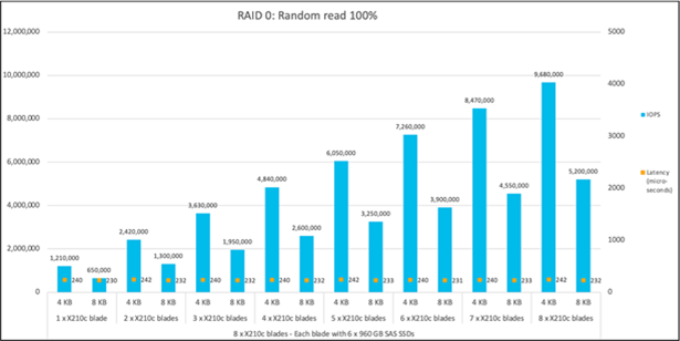
Figure 8 shows the performance of the SAS SSDs under test for X210c M6 compute node blades with a UCS X9508 chassis for a 100-percent random-read access pattern with both 4 KB and 8 KB block sizes. The graph shows the performance of 1.2M IOPS with average latency of 240 microseconds when six SAS SSDs populated on a single X210c M6 compute node for a 4 KB block size.
The aggregate performance of ~9.6M IOPS with average latency of 242 microseconds is achieved with all eight X210c M6 compute nodes in the chassis. This demonstrates a linear scaling of IOPS without any variation of latency. A similar trend is observed for an 8 KB block size, as can be seen in the graph below.
Random read 100%
Random write (100%)
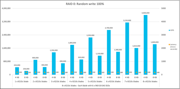
Figure 9 shows the performance of the SAS SSDs under test for 8 x X210c M6 compute node blades with a UCS X9508 chassis with a 100-percent random-write access pattern with 4 KB and 8 KB block sizes. The graph shows the performance of 450K IOPS with latency of 190 microseconds with six SAS SSDs on a single X210c M6 compute node.
The aggregate performance of 3.6M IOPS with latency of 190 microseconds is achieved with all eight X210c M6 compute nodes in the chassis. Again, like the random-read results, these results also follow a linear IOPS scaling without any variation of latency. A similar trend is observed for an 8 KB block size, as can be seen in the graph below.
Random write 100%
Random read:write (70R:30W)
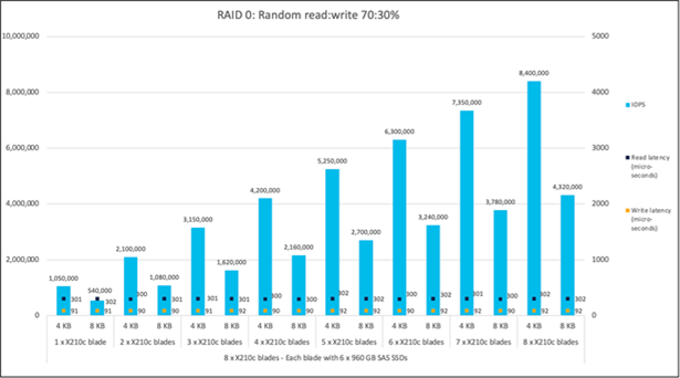
Figure 10 shows the performance of the SAS SSDs under test for 8 x X210c M6 compute node blades with a UCS X9508 chassis with a 70:30-percent random-read:write access pattern. The graph shows the performance of 1.05M IOPS (combined IOPS of read and write) with a read latency of 301 microseconds and a write latency of 91 microseconds with six SAS SSDs on a single X210c M6 compute node for a 4 KB block size.
The aggregate performance of 8.4M IOPS with a read latency of 302 microseconds and a write latency of 92 microseconds is achieved with a total of forty-eight SAS SSDs on 8 x X210c M6 compute node blades for a 4 KB block size, maintaining the linearity.
Random read:write 70:30%
Sequential read (100%)
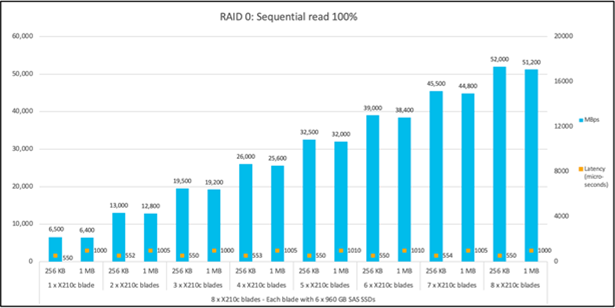
Figure 11 shows the performance of the SAS SSDs under test for 8 x X210c M6 compute node blades with a UCS X9508 chassis with a 100-percent sequential-read access pattern. The graph shows the performance of 6500 MBps with a latency of 550 microseconds with six SAS SSDs on a single X210c M6 compute node for a 256 KB block size.
The aggregate performance of ~52,000 MBps with a latency of 550 microseconds is achieved with a total of forty-eight SAS SSDs for a 256-KB block size. A similar linear trend (scaling from one blade to eight blades) is observed for 1 MB block size as well.
Sequential read 100%
Sequential Write (100%)
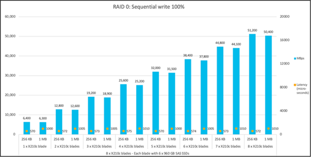
Figure 12 shows the performance of the SAS SSDs under test for 8 x X210c M6 compute node blades with a UCS X9508 chassis with a 100-percent sequential-write access pattern. The graph shows the performance of 6400 MBps with a latency of 570 microseconds with six SAS SSDs on a single X210c M6 compute node for a 256 KB block size.
The aggregate performance of ~51,000 MBps with a latency of 572 microseconds is achieved with a total of forty-eight SAS SSDs on 8 x X210c M6 compute node blades for a 256 KB block size. A similar linear trend (scaling from one blade to eight blades) is observed for a 1 MB block size as well.
Sequential write 100%
SAS SSD RAID 5 performance
Random read:write 70:30%
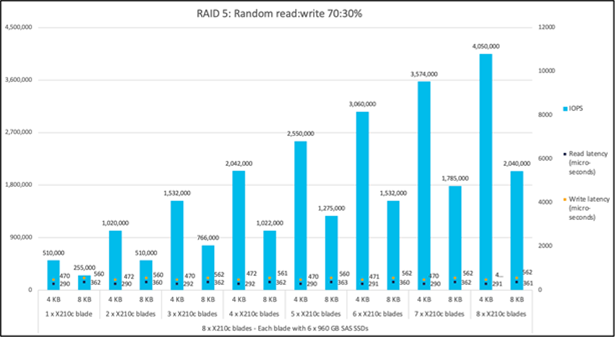
Figure 13 shows the performance of the SAS SSDs under test for a RAID 5 configuration on 8 x X210c M6 compute node blades with a UCS X9508 chassis with a 70:30-percent random-read:write access pattern. The graph shows the performance of 510K IOPS (combined IOPS of read and write) with a read latency of 290 microseconds and a write latency of 470 microseconds with six SAS SSDs on a single X210c M6 compute node for a 4 KB block size.
The aggregate performance of ~4M IOPS with a read latency of 291 microseconds and a write latency of 472 microseconds is achieved with a total of forty-eight SAS SSDs on 8 x X210c M6 compute node blades for a 4 KB block size, maintaining linearity. A similar linear trend (scaling from one blade to eight blades) is observed for an 8 KB block size as well.
Random read:write 70:30%
Random read:write 50:50%
Figure 14 shows the performance of the SAS SSDs under test for a RAID 5 configuration on 8 x X210c M6 compute node blades with a UCS X9508 chassis with a 50:50-percent random-read:write access pattern. The graph shows the performance of 350K IOPS (combined IOPS of read and write) with a read latency of 300 microseconds and a write latency of 521 microseconds with six SAS SSDs on single X210c M6 compute node for a 4 KB block size.
The aggregate performance of ~2.8M IOPS with a read latency of 302 microseconds and a write latency of 520 microseconds is achieved with a total of forty-eight SAS SSDs on 8 x X210c M6 compute node blades for a 4 KB block size, maintaining linearity. A similar linear trend (scaling from one blade to eight blades) is observed for an 8 KB block size as well.
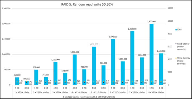
Random read:write 50:50%
SAS SSD RAID 10 performance
RAID 10 configuration combines disk mirroring and disk striping and requires a minimum of four disks. For the performance tests with a RAID 10 configuration with sequential read and write, one volume is created with four disks, configured with two spans of two disks each.
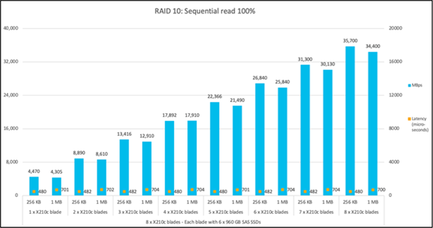
Sequential read (100%)
Figure 15 shows the performance of the SAS SSDs under test for 8 x X210c M6 compute node blades with a UCS X9508 chassis with a 100-percent sequential-read access pattern for a RAID 10 configuration. The graph shows the performance of 4470 MBps with a latency of 480 microseconds with four SAS SSDs on single X210c M6 compute node for a 256 KB block size.
The aggregate performance of ~35,000 MBps with a latency of 480 microseconds is achieved with a total of thirty-two SAS SSDs for a 256 KB block size. A similar linear trend (scaling from one blade to eight blades) is observed for a 1 MB block size as well.
Sequential read 100%
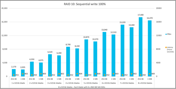
Sequential write (100%)
Figure 16 shows the performance of the SAS SSDs under test for 8 x X210c M6 compute node blades with a UCS X9508 chassis with a 100-percent sequential-write access pattern for a RAID 10 configuration. The graph shows the performance of 2170 MBps with a latency of 451 microseconds with four SAS SSDs on a single X210c M6 compute node for a 256 KB block size.
The aggregate performance of ~17,000 MBps with a latency of 450 microseconds is achieved with a total of thirty-two SAS SSDs on 8 x X210c M6 compute node blades for a 256 KB block size. A similar linear trend (scaling from one blade to eight blades) is observed for a 1 MB block size as well.
Sequential write 100%
For additional information, refer to: https://www.cisco.com/c/en/us/products/servers-unified-computing/ucs-x-series-modular-system/index.html
Intersight configuration guide: https://www.cisco.com/c/en/us/products/cloud-systems-management/intersight/index.html?ccid=cc001268
For information on BIOS tunings for different workloads, refer BIOS tuning guide, refer to: https://www.cisco.com/c/en/us/products/collateral/servers-unified-computing/ucs-b-series-blade-servers/performance-tuning-guide-ucs-m6-servers.pdf
For information on the fio tool, refer to: https://fio.readthedocs.io/en/latest/fio_doc.html
Table 4 lists the details of the server under test.
Table 4. Blade properties
| Name |
Value |
| Product names |
Cisco UCS X210c Compute Node |
| CPUs |
CPU: Two 2.80-GHz Intel Xeon Gold 6342 |
| Number of cores |
24 |
| Number of threads |
48 |
| Total memory |
512 GB |
| Memory DIMMs (16) |
32 GB x 16 DIMMs |
| Memory speed |
3200 MHz |
| VIC adapter |
Cisco UCSX-V4-Q25GML VIC 14425 4x25G mLOM |
| SFF NVMe SSDs |
6.4 TB 2.5-inch Intel D7-P5600 NVMe High Perf Medium Endurance (UCSC-NVMEI4-I6400) |
| SFF SAS SSDs |
960 GB 2.5-inch enterprise value 12G SAS SSD (UCS-SD960GK1X-EV) |
Table 5 lists the server BIOS settings applied for disk I/O Testing
Table 5. Server BIOS settings
| Name |
Value |
| Firmware version |
5.0(1b) |
| BIOS version |
5.0.1d |
| FI firmware version |
9.3(5)I42(1f) |
| DRAM refresh rate |
1x |
| Hardware prefetcher |
Enable |
| Adjacent-cache-line prefetcher |
Enable |
| DCU streamer |
Enable |
| DCU IP prefetcher |
Enable |
| NUMA |
Enable |
| Memory refresh enable |
1x Refresh |
| Energy-efficient turbo |
Enable |
| Turbo mode |
Enable |
| EPP profile |
Performance |
| CPU C6 report |
Enable |
| Package C state |
C0/C1 state |
| Power Performance Tuning |
OS controls EPB |
| Workload configuration |
I/O sensitive |
Note: Rest of the BIOS settings are platform default values
Table 6 lists the recommended FIO settings.
Table 6. Recommended FIO settings
| Name |
Value |
| FIO version |
Fio-3.19 |
| Filename |
Device name on which FIO tests should run |
| Direct |
For direct I/O, page cache is bypassed |
| Type of test |
Random I/O or sequential I/O, read, write, or mix of read:write |
| Block size |
I/O block size: 4, 8, or 256K, or 1M |
| I/O engine |
FIO engine - libaio |
| I/O depth |
Number of outstanding I/O instances |
| Number of jobs |
Number of parallel threads to be run |
| Run time |
Test run time (for example: 1800 seconds) |
| Name |
Name for the test |
| Ramp-up time |
Ramp-up time before the test starts (e.g: 10 seconds) |
| Time-based |
To limit the run time of test |
Note: The SSDs were tested with various combinations of outstanding I/O and number of jobs to get the best performance within acceptable response time. The drives were preconditioned (sequential write/random write for entire disk) before actual fio tool measurements are taken.