Cisco UCS X-Series Quick Start Guide
Available Languages
Bias-Free Language
The documentation set for this product strives to use bias-free language. For the purposes of this documentation set, bias-free is defined as language that does not imply discrimination based on age, disability, gender, racial identity, ethnic identity, sexual orientation, socioeconomic status, and intersectionality. Exceptions may be present in the documentation due to language that is hardcoded in the user interfaces of the product software, language used based on RFP documentation, or language that is used by a referenced third-party product. Learn more about how Cisco is using Inclusive Language.
The purpose of this document is to assist with the basic installation and configuration of the Cisco UCS X-Series solution. Much of the content in this guide was copied directly from several sources, including but not limited to the following:
● Cisco UCS X9508 Server Chassis Installation Guide.
● Getting Started with Intersight.
● Cisco Intersight Handbook.
● Cisco Intersight Help Center.
● Cisco UCS 6400 Series Fabric Interconnect Hardware Installation Guide.
● Cisco UCS 6500 Series Fabric Interconnect Hardware Installation Guide.
● Deploy Cisco UCS X210c Compute Node with Cisco Intersight Management Mode for VDI.
Intended audience
This guide is intended primarily for data center administrators with responsibilities and expertise in one or more of the following:
● Server administration
● Storage administration
● Network administration
● Network security
The specifications and information regarding the products in this guide are subject to change without notice. all statements, information, and recommendations in this manual are believed to be accurate but are presented without warranty of any kind, express or implied. users must take full responsibility for their application of any products.
The software license and limited warranty for the accompanying product are set forth in the information packet that shipped with the product and are incorporated herein by this reference. if you are unable to locate the software license or limited warranty, contact your cisco representative for a copy.
Fabric Interconnect hardware feature overview
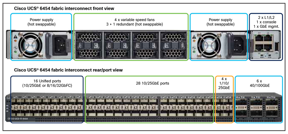
54-port Fabric Interconnect (1RU) model 6454
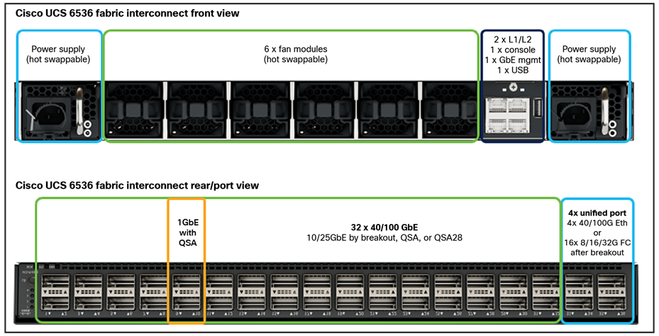
54-port Fabric Interconnect (1RU) model 6536

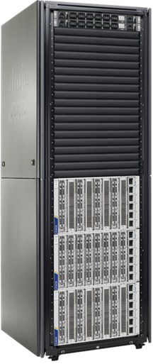
Compute chassis and blades (7U) model X9508
Prior to installing the hardware, it would be best to review all power, cooling, rack, and environmental requirements that are outlined in the Fabric Interconnect and chassis installation guides:
Cisco UCS 6400 Series Fabric Interconnect requirements
Please refer to the “Cisco UCS 6400 Series Fabric Interconnect Hardware Installation Guide” for detailed information related to the installation of 6400 series Fabric Interconnects.
Cisco UCS 6500 Series Fabric Interconnect requirements
Please refer to the “Cisco UCS 6500 Series Fabric Interconnect Hardware Installation Guide” for detailed information related to the installation of 6500 series Fabric Interconnects.
Cisco UCS X9508 Server Chassis requirements
Please refer to the “Cisco UCS X9508 Server Chassis Installation Guide” for detailed information related to the installation of X9508 chassis.
Managing Cisco X-series with Cisco Intersight Infrastructure Service
Cisco Intersight™ Infrastructure Service (IIS)—built on the Cisco Intersight hybrid-cloud operations platform—is Cisco’s cloud-based infrastructure management solution delivered as a service. IIS is next-generation software that helps IT operations teams visualize, control, and automate compute, storage, and networking infrastructure—wherever it is—from one place.
● Visualize – Unlike traditional, siloed tools, Cisco Intersight gives you one consolidated dashboard to see your on-premises, cloud, and edge infrastructure—including their real-time status and interdependencies.
● Control – Whereas traditional infrastructure management typically requires multiple, repeated tasks, this platform lets you easily perform operations actions across your global infrastructure with just a few clicks so you stay in constant control. Deploy, configure, and operate servers, VMs, storage, and networking throughout their lifecycle, from one place anytime, anywhere.
● Prevent and resolve – Greater control to prevent and resolve issues stemming from computing hardware using advisories, hardware compatibility lists, proactive RMAs, firmware upgrades, and connected TAC are some of the biggest benefits operations teams get from Intersight.
● Automate – Instead of having to perform tasks manually, Intersight lets you automate day-0, day-1, and day-2 tasks and workflows to accelerate infrastructure operations.
Some of the key benefits of this platform include:
● Speed: Deploy, configure, and maintain infrastructure in minutes̶—at scale—anytime, anywhere.
● Consistency: Ensure consistent server configuration across your global infrastructure to identify and eliminate configuration drift.
● Security: Apply strict security standards across infrastructure operations; continuously identify and mitigate potential security threats.
● Audits and compliance: Log all actions taken on your infrastructure; ensure consistent adherence to policies through automation, templates, and cross-domain management.
● Control and manage: Operate Cisco® and third-party infrastructure from one place.
● Reduce or eliminate downtime: Address potential hardware, OS, and software issues before they impact users, or minimize them when they occur.
● Improve productivity: Reduce time spent on support, maintenance, and operation of multiple infrastructure domains, including networking, compute, storage, virtualization, and integrated systems.
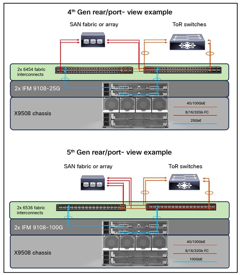
Rear/port view cabling example
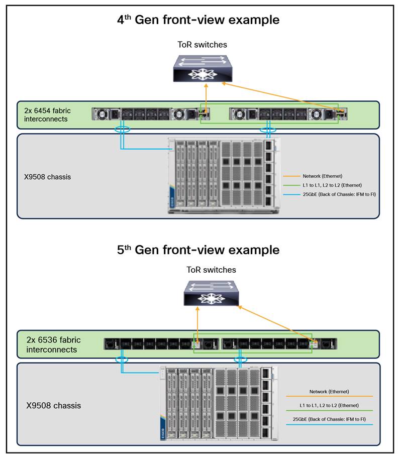
Front view cabling example
1. Starting the X-Series domain configuration
1.1 Configure the first Fabric Interconnect for Cisco Intersight management
Depending on the state of each Fabric Interconnect, this first set of steps may not be necessary. If you see a message “Switch can now be configured from GUI” as shown in the following image, you must follow these steps:
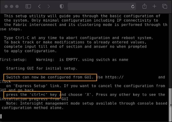
Press CTRL-c as instructed on the screen to halt the GUI configuration process. You can configure Cisco Intersight mode only through the console.
Type “X” followed by Enter. Because of screen wrapping, you may not be able to see the “X” that you typed, but don’t worry about that.
Refer to the following image for the next steps:
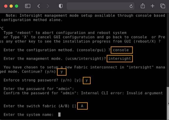
You will be asked to enter the configuration method. Remember that you can configure Cisco Intersight mode only through the console, so type console.
For the management mode, type Intersight.
The wizard will ask you to confirm that you are setting up a new Fabric Interconnect in Intersight Managed Mode. Type “y” to confirm.
You will be asked whether or not to enforce strong passwords. Make your selection and input the password you wish to use.
For the switch fabric (A or B), choose A.
Name the system (Note that the name assigned to the system in this step will be applied to every chassis and server connected to it. This name cannot be changed later without erasing the Fabric Interconnect configuration).
Enter the IP address for Fabric Interconnect A.
Enter the netmask for the management network.
Enter the default gateway for the management network.
Enter the IP address of the Domain Name System (DNS) servers.
Configure the default domain name.
The last step is to confirm all of your settings. Verify that your settings are correct and type “yes” to continue.
Congratulations. You have configured Fabric Interconnect A (FI-A) in Intersight Managed Mode. It will take several minutes for the Fabric Interconnect to reboot. Before configuring the second fabric interconnect, please wait until the Fabric interconnect A fully reboots. Once the first Fabric Interconnect has rebooted, the second Fabric Interconnect will be able to detect the first Fabric Interconnect presence and will allow its configuration as a cluster. Proceed to the next section to configure the second Fabric Interconnect.
1.2 Configure the second Fabric Interconnect for Intersight management
Configuring the second Fabric Interconnect is much faster because it obtains most of its configuration from Fabric Interconnect A. These first few steps of the configuration are represented in the image following step 7 below:
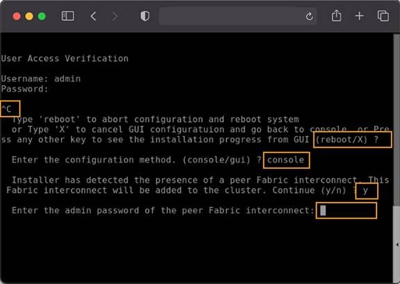
You may need to hit the Enter key to wake up the console for Fabric Interconnect B (FI-B). If you see nothing on the screen, the fabric interconnect might be in the mode where it is waiting for you either to configure it from the GUI or to press CTRL-c to interrupt the process. Just as you did for the FI-A setup, press CTRL-c.
As you did for the FI-A setup, press “x” and then Enter. As with FI-A, you may not actually see the “x” when you type it.
For the configuration method, enter console. Remember that you can configure Intersight mode only through the console.
FI-B should detect that its peer (FI-A) is already configured and will ask if it should attempt to join that cluster. Type “y” and hit Enter.
Enter the password you used for FI-A.
At this point, FI-B will pull the networking configuration from its peer. You only need to provide FI-B with an IP address.
Type “yes” to save the configuration and restart the Fabric Interconnect.
Congratulations. You have configured Fabric Interconnect B in Cisco Intersight Managed Mode. It will take several minutes for the Fabric Interconnect to reboot. Proceed to the next section to claim the Fabric Interconnect pair into the Cisco Intersight platform.
1.3 Claim the Fabric Interconnects in the Cisco Intersight platform
For this step, you will connect to the Device Console on the Fabric Interconnect pair. There is no longer an instance of Cisco UCS Manager, and when you browse to one of the Fabric Interconnects, you will be prompted to log into the Device Console instead. This console is where you obtain a Device ID and Claim Code in order to claim this new domain in the Cisco Intersight platform.
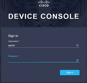
Using one of the supported browsers (see section 6 of this document), connect the IP address of Fabric Interconnect A (you should see the Device Console login screen like the one shown in the following image). Ensure that HTTPS is used or you will not be able to connect to the Device Console.
Use the credentials you configured earlier during Fabric Interconnect setup to log in.
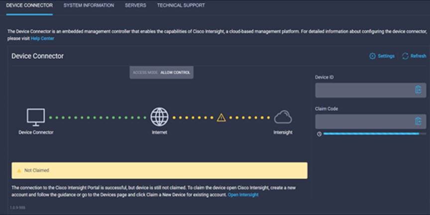
Go to the Device Connector tab. If there is an error on this page saying, “Some unknown internal error has occurred,” it is likely because this domain has been claimed in Cisco Intersight already. Please click the refresh button in the device connector view, but if the problem persists, reach out to the Cisco® Technical Assistance Center (TAC) to address this problem. If instead you see a screen like the one shown below (which shows that the Fabric Interconnect can connect to Cisco Intersight but is not yet claimed), then proceed to the next step.
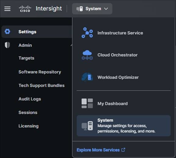
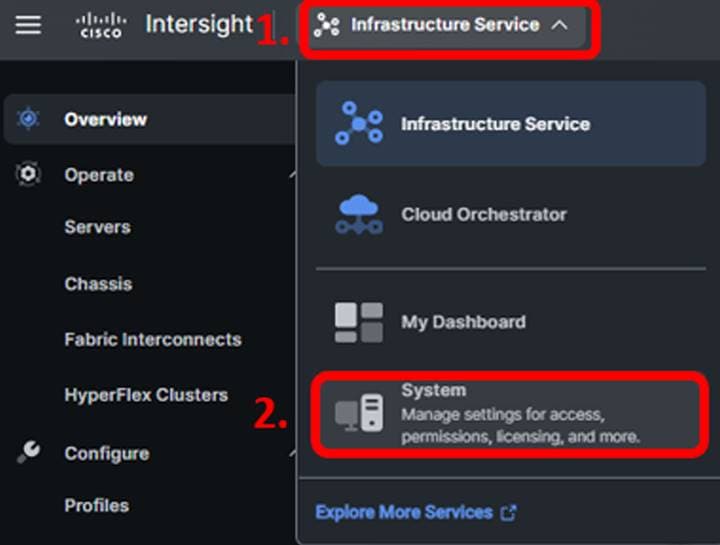
Browse to intersight.com from your computer. Use Cisco Intersight credentials for an account that has at least the Device Technician role. The roles Device Technician and Device Administrator allow you to claim and unclaim devices but do little else. Once authenticated, make sure you have selected “System” from the top drop-down menu as shown below:
Select Admin -> Targets and then click the blue “Claim a New Target” button in the upper right portion of the window.
For target type, select Cisco UCS Domain (Intersight Managed) and click the Start button.
You’ll need the Device ID and Claim Code from the Device Console. Try copying those values into Cisco Intersight.
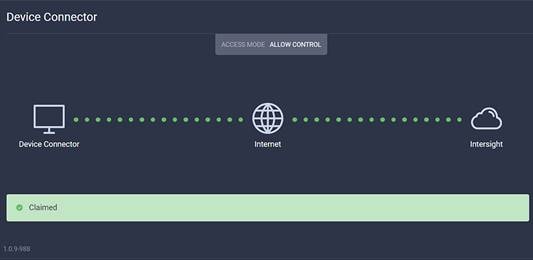
Click the blue Claim button after pasting the Device ID and Claim Code. Shortly after the claim succeeds, the Fabric Interconnect Device Connector should show a status of “Claimed” as shown in the following image:
Although the Device Technician can claim a target, the Device Technician cannot put that target into the right Intersight organization. Currently, only an Account Administrator can do that. If your credentials don’t have that privilege level, please reach out to someone within the Intersight organization who has Account Administrator credentials.
Congratulations. You have claimed a domain in Cisco Intersight.
After the domain is claimed to Intersight, all configuration steps for servers, chassis, and Fabric Interconnects are initiated through Intersight. For more information about Intersight-managed domains, refer to the Cisco Intersight Managed Mode Configuration Guide.
1.4 Upgrade Fabric Interconnect firmware
Before discovering what hardware is connected to the Fabric Interconnects, you should check to see if a recommended firmware upgrade is available for the Fabric Interconnects. After logging into Intersight, select the drop-down box in the upper left corner of the page and select “Infrastructure Service” if it is not currently selected:
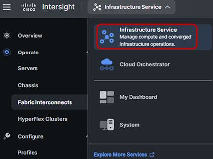
In the left side of the screen, select Operate -> Fabric Interconnects.
From the Fabric Interconnect screen, click the three dots at the end of the row for either of the Fabric Interconnects and select “Upgrade Firmware.”
On the Version page, select “Start.”
The General page should show the current bundle version that is installed on the selected Fabric Interconnect. Click “Next” on the General step to proceed to the Version step.
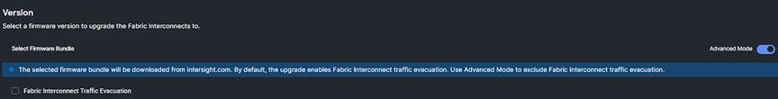
Step 2 of the upgrade allows you to select a different version of firmware. Fabric Interconnects in this state (with no discovered chassis) do not need to evacuate server traffic. You must select “Advanced Mode” and uncheck “Fabric Interconnect Traffic Evacuation,” as shown in the following image.
After selecting the version you wish to apply, click “Next” to proceed to the Summary page.
Step 3 of the upgrade is simply a confirmation screen that should show both Fabric Interconnects with their current firmware version and an icon showing the intended firmware version. Click “Upgrade” and click “Upgrade” again on the next popup box when prompted if you wish to proceed with the firmware upgrade.
The Intersight Requests icon will help you keep track of long-running tasks such as firmware updates. It is the left-most icon shown in the following images where three different states for the icon are shown:
Circle with a check mark: All user requests have been completed. You can click this icon to view completed tasks.
![]()
Spinning circle with a check mark: The number shown is the number of user requests currently being worked on by Intersight. You can click this icon to view active tasks.
![]()
Solid circle with a check mark and number: The number shows the number of tasks that require user action or intervention. You can click the icon to view these actions and then act on them.
![]()
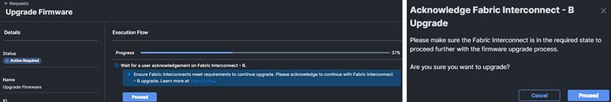
You will be required to confirm that it is okay to start upgrading the Fabric Interconnect. At this point, you can watch the firmware upgrade process by clicking on the “Upgrade Firmware” request from the active requests window.
Once you have clicked on the active request and are viewing the Execution Flow, click the “Proceed” button when prompted and click “Proceed” again on the popup as shown below when it is time to acknowledge it is okay to upgrade Fabric Interconnect B:
Once the firmware upgrade for Fabric Interconnect B has completed, you will be prompted to proceed with upgrading Fabric Interconnect A. Click “Proceed” and click “Proceed” again on the popup when prompted, as shown below:
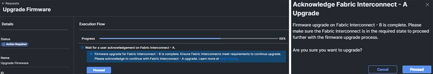
It will take about 15 to 20 minutes for Fabric Interconnect A to complete its upgrade. If you browse away from the firmware upgrade status, you can always get back to it by clicking on the spinning circle in the Intersight task bar to see current or completed tasks. Browse to Operate -> Fabric Interconnects to confirm that both Fabric Interconnects are now running the correct version of firmware.
Congratulations. You have performed a Fabric Interconnect firmware update through Intersight. Proceed to the next section to discover what hardware is connected to that domain.
1.5 Create a UCS Domain Profile
In this section, you will create a domain profile for the newly claimed domain. Intersight cannot discover any hardware connected to the Fabric Interconnects until its ports are configured, and that is done through a domain profile. You can create each of the policies the profile will use before you create it, or you can create the policies while creating the profile. We will do the latter in this guide.
The following reference details the policies involved in creating a domain profile. Not all policies are required. Please refer to Domain Policies for more details about each domain policy type.
While logged in to Intersight, choose CONFIGURE > Profiles > UCS Domain Profiles > Create UCS Domain Profile as shown here:
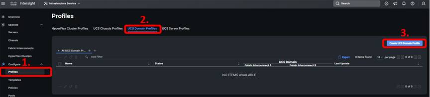
At the intro screen for the wizard, click “Start.”
Give the profile a name, a description, and any tags you want to apply to it. Click “Next.”
Step 2 of the domain creation wizard is UCS Domain Assignment. The domain you name created in the previous step should now be seen in this step. Select that domain and click “Next.”
Step 3 of the domain creation wizard is VLAN and VSAN configuration. Notice that you can apply a different policy to the A and B fabrics (if using the same VLANs on Fabric A and B, you can use the same policy for both). Intersight allows for the creation of policies prior to configuring the equipment. If the VLAN/VSAN policies were created prior to the configuration, select the policies needed for this deployment for both fabric interconnects. If creating new policies, click “Select Policy” and then “Create New” as show below:
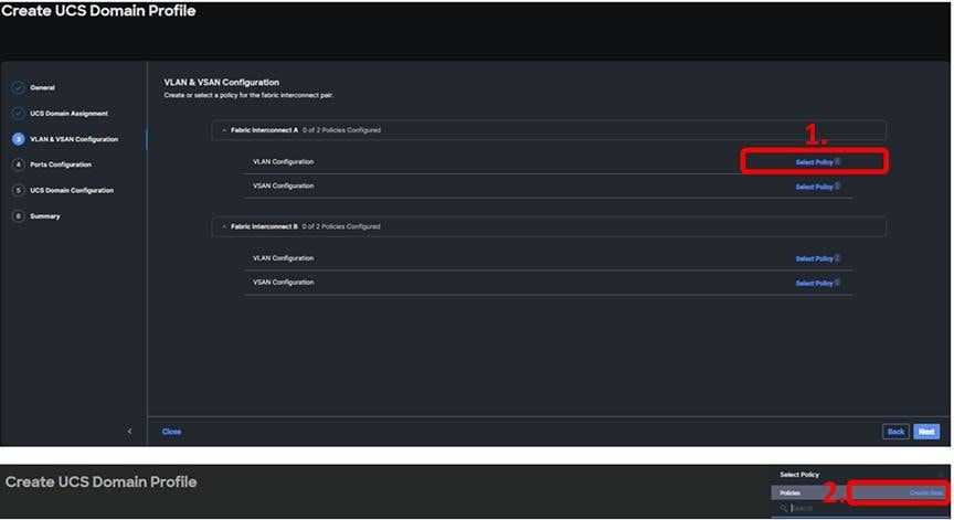
In the General step, give the policy a name, a description, and any tags you want to apply to it. Click “Next.”
In the Policy Details step, select the Add VLANs button.
In the Add VLANs step, add the names/VLAN IDs needed.
If a multicast policy hasn’t been created, create a new multicast policy. Creating a multicast policy involves selecting the snooping and querier state. Both settings have a tooltip next to them describing their function.
When finished with the VLAN configuration step, click “Add.”
If connecting to a SAN, create a VSAN configuration policy (Note: It is best practice for VSAN IDs to be different for each fabric, so you should create two policies.)
After the newly created policies have been selected for both fabrics, Click “Next.”
Step 4 of creating the Domain Profile is to create a Port Policy. If you follow internal standards for cabling Cisco UCS domains, you can create this port policy once and reuse it for every new domain, saving significant setup time.
On the ports configuration screen that shows an image of a Fabric Interconnect, click on “Select Policy” for Fabric Interconnect A.
Click “Create New” to create a new policy if there was not an existing policy created prior to this deployment.
In the first step of creating the Port Policy, give the policy a name and select UCS-FI-xxxx (xxxx being your specific FI model) for the switch model. You can optionally give the profile a description and any tags you like. Click “Next.”
In the second step of creating a Port Policy, you have the option to set some number of the unified ports to Fibre Channel by moving the slider. Note that in firmware 4.1(3c) and later, you can change the position of the slider after deploying the Domain Profile, but it will require rebooting both Fabric Interconnects. Changing any of the unified ports between Ethernet and Fibre Channel is a hardware change and requires a reboot. Click “Next.”
In the third step of creating the Port Policy, you are presented with a Breakout Option configuration step. Various ports on Fabric Interconnects are capable of leveraging breakout cables. If using breakout cables, proceed with configuring the ports and when finished, click “Next.”
In the fourth and final step of creating the Port Policy, you must change the role of ports connected to the chassis to Server Ports. While on the Port Roles tab (tabs are shown in the image that follows), select the ports that are connected to the X9508 IFMs (port 47) and click “Configure” to select “Server” as their port role. Click “Save” after configuring the ports.
Click the Port Channels tab and click “Create Port Channel.” Add the ports connecting to the switch (ports 49 and 50) to an Ethernet Uplink Port Channel with a port channel ID of 1 and admin speed of Auto. If you need to define additional details for flow control, link aggregation, and link control policies,
Please review additional information about these policies at: https://intersight.com/help/saas/features/fabric_interconnects/configure#domain_policies
Click “Save” to save the port policy. You now have defined a reusable port policy and should be returned to step 4 of the domain profile configuration.
Click “Select Policy” to choose a port policy for the second Fabric Interconnect and choose the port policy that you just created. Click “Next” to move to step 5 of domain profile configuration.
Step 5 of the domain profile configuration involves creating several policies. This guide covers the steps for creating the Network Time Protocol (NTP), Network Connectivity (DNS), and System quality-of-service (QoS) policies, but you should familiarize yourself with the capabilities of the other policies as well. Consult the online Intersight help for more information.
Create a new NTP policy that specifies the NTP servers being used for this deployment and choose the appropriate time zone.
Create a new Network Connectivity policy that specifies the primary DNS and the alternate DNS.
Create a System QoS policy. This step is required for domain profile creation.
Syslog, Simple Network Management Protocol (SNMP), and Switch Control policies are optional. You can explore and create them if you choose. Click “Next” when you are ready to move to the next step.
The Summary page allows the user to view the configuration that will be deployed using the steps previously taken. Once the information has been reviewed and you have confirmed the configuration meets the requirements for the deployment, click “Deploy” (and then click “Deploy” again in the popup) to apply this UCS domain profile. You can watch the status of the tasks associated with this action by clicking on any of the requests. These tasks will be completed quickly and chassis discovery will begin.
Congratulations, you have created and applied a UCS domain profile in Intersight. This step had many tasks, but fewer than are required for configuring a traditional UCS domain. Additionally, you can reuse many of the policies you created to deploy a second domain in Intersight Managed Mode much faster.
1.6 Verify discovered chassis
The chassis will be discovered almost immediately, but it will take longer for the compute node(s) to be discovered. In Intersight, browse to Operate -> Chassis to see the newly discovered chassis. The chassis will likely show up empty because it is still performing discovery. Now is a good time to start creating pools, templates, and profiles. Proceed to the next section.
2. Starting the X-Series server configuration
2.1 Create Server Profile Template
In this step, you will create a server profile template. Intersight allows converting a server profile to a template, but let’s just create a template directly instead. Just know that you can take any server profiles that you have already created in your own Intersight account and convert them into templates.
The following reference details the policies involved in creating a server profile and server profile template. Not all policies are required. Please refer to Server Policies for more details about each server policy type.
Before creating the profile, create some of the policies that you will need:
In Intersight, browse to Configure -> Policies and click “Create Policy”. Under the “UCS Server” Platform Type, select “Local User” and then click “Start.“ The local user will be the user whom you use to connect to KVM.
Give the local user policy any name, description, and tags that you like. Click “Next.”
This policy can be created for All Platforms, UCS Server (Standalone), or UCS Server (FI-Attached). For this example, we are choosing “All Platforms,” but select the option best suited for your organization. Under Local Users, choose “Add New User,” select the “+” symbol next to New User, define a username and a password (also confirm the password), and set that user to a role of admin (you can create multiple user accounts with this policy). Use something unique for the local user account. For the Password Properties, choose the options that best meet your organization’s security policy. Best practice is to also set the Password History to “0”; this should prevent the CIMC from rejecting the same password when the policy is redeployed at a later time. When finished, click “Create.”
Next, you will create a LAN Connectivity policy. This policy specifies the number and mapping of virtual Network Interface Cards (vNICs). It takes several steps, so this guide will walk you through building this policy prior to building a server profile rather than building the policy in line with creating the profile.
In Intersight, browse to Configure -> Policies.
Click “Create Policy,” select “UCS Server” under Platform Type, select “LAN Connectivity,” then click “Start.”
In step 1 of the LAN Connectivity policy creation, it is important to select “UCS Server (FI-Attached)” for the target platform. Give the policy a name, a description, and any tags you want to apply to it, then select “Next.”
During step 2 of the LAN Connectivity policy creation, you will create two vNICs and assign a Media Access Control (MAC) pool and policies to each vNIC. The policies have been left at their default values, but you should understand the purpose of these policies before installation. The next few numbered steps in this guide will help you complete step 2 of the LAN Connectivity Policy for this example (address each step as your environment requires if it differs from the examples below).
For iSCSI Initiator (IQN), leave this set to None as we are not using iSCSI in this example.
For vNIC placement, choose Auto vNICs Placement unless there is a requirement otherwise.
Click “add vNIC” for Fabric A and give the vNIC a name (some examples are names such as vNIC0 or Eth0).
In this example, we will be using a MAC pool. Click “Select Pool” for the MAC Address Pool. If you created a MAC Address pool previously for this environment, you can select that now. If you didn’t, you can create one in this step by selecting “Create New” and walking through the steps to create a new pool.
For Switch ID, choose switch A.
Create an Ethernet Network Group Policy, Ethernet Network Control Policy, Ethernet QoS, and Ethernet Adapter policy according to the configuration requirements for the new environment.
Click “Add” to complete the creation of the first vNIC. You should follow these steps again to create a second vNIC for Switch ID B with a name similar to what was used in the first vNIC (examples: vNIC1 or Eth1).
After you have created the correct number of vNICs required for the host(s), click “Create” to complete the creation of the LAN Connectivity policy.
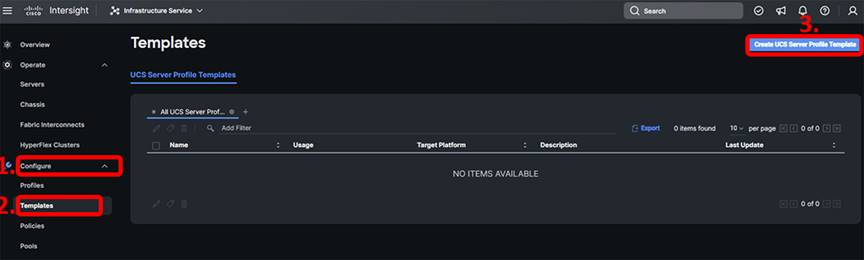
Now that you have completed some of the initial work, it is time to create the server profile template.
In Intersight, browse to Configure -> Templates and click “Create UCS Server Profile Template”:
In the first step, give the template a name, a description, and any tags you want to apply to it. Be sure to select “UCS Server (FI-Attached)” for the target platform. When finished, select “Next.”
Step 2 is for setting the Compute Configuration. Similar to previous steps, you can have the pools/policies created prior to starting the Server Profile Template creation and utilize the precreated pools/policies in this step or you can create new policies directly from this step. Note: The UUID pool prefix requires the format to be hexadecimal using xxxxxxxx-xxxx-xxxx as an example for the prefix’s required digits. The suffix has a similar hexadecimal requirement but using xxxx-xxxxxxxxxxxx as an example for the suffix’s required digits.
In step 2, you will also set the BIOS, boot order, power, and virtual media policies. For the BIOS policy, it is recommended that you refer to the Performance Tuning Guide for Cisco UCS Servers based on the platform type you are deploying (for example, Cisco UCS X210c M6 Compute Node, Cisco UCS X210c M7 Compute Node, etc.)
The goal for our example is to create a virtual media policy that attempts to boot first from virtual media and second from the local disk, but we recommend adding your own for familiarity. For the Boot Order, select “create new” if one hasn’t already been created for this environment and give it a name, a description, and any tags you want to apply to it. Click “Next.” When creating a boot policy, select the “Add Boot Device” drop down, and choose the three following options:
Add Local Disk.
Add the virtual media with CIMC-mapped DVD sub-type.
Add the virtual media with KVM-mapped DVD sub-type.
Next, a virtual media policy will be needed to enable virtual media. Unlike traditional UCS servers, KVM-mapped virtual media will not work if it is not enabled by policy. Next to Virtual Media, click “select policy,” select “create new” if one hasn’t already been created for this environment, and give it a name, a description, and any tags you want to apply to it. Click “Next,” then “Create.” Click “Next“ to proceed.
Step 3 of the server profile template configuration allows you to configure multiple management policies. Start with local user and select the policy you created earlier.
For the IMC Access policy, select “create new” if one hasn’t already been created for this environment and give it a name, a description, and any tags you want to apply to it (note that the purpose of this policy is to define an IP pool for IMC as well as VLAN, gateway, and DNS information).
Create a new Virtual KVM policy by selecting “create new” if one hasn’t already been created for this environment and give it a name, a description, and any tags you want to apply to it. Simply use the default settings. Click “Next” to proceed.
Step 4 of the server profile template configuration allows you to configure storage-related policies. Configure either of these policies. Click “Next” to proceed.
Step 5 of the server profile template configuration allows you to configure network policies. For the LAN connectivity policy, choose the policy you built earlier in the guide. Click “Next” to proceed.
The final step of the server profile template configuration is the summary page, and you can either exit (Close) or Derive Profiles. You will derive the profiles later, so for now, click “Close.”
Congratulations. You have created a server profile template and will soon get a chance to use it. First you should verify if there is a recommended firmware update for the server(s).
2.2 Update server firmware
Intersight allows for upgrading firmware on multiple servers at once. At this point, any servers attached to the domain should have completed discovery.
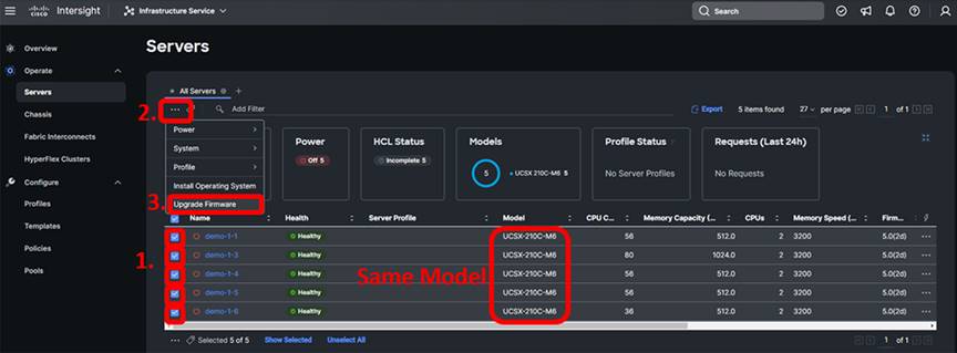
In Intersight, browse to Operate -> Servers. Intersight should have discovered the servers in the domain. If you don’t see them, hit the refresh button in your browser:
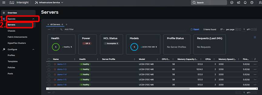
Select all of the discovered servers that are of the same type by clicking the checkbox next to each one. Bulk firmware upgrade operations are supported only on similar servers. You can sort the servers table by Model if there is any confusion.
With one or more servers selected, click the ellipses (…) at the top or bottom of the server table and choose Upgrade Firmware:
The first step of the firmware upgrade process introduces the firmware upgrade wizard and allows you to change your mind about which servers you want to upgrade. Click “Next” to proceed.
The second step of the firmware upgrade process allows you to select the upgrade firmware version. Select the radio button for the firmware version that best applies to your deployment then click “Next.” On the Summary page, verify the information is correct based on the desired upgrade, and if it meets the criteria, select “Upgrade,” select “Reboot Immediately to Begin Upgrade” if the servers are at a state where it is safe to reboot, and click “Upgrade” again on the popup. This process takes roughly 30 minutes, and the process can be monitored by selecting the active requests in the upper righthand portion of the screen.
2.3 Assign profiles to servers
After you have completed the firmware update, you can assign profiles to the servers.
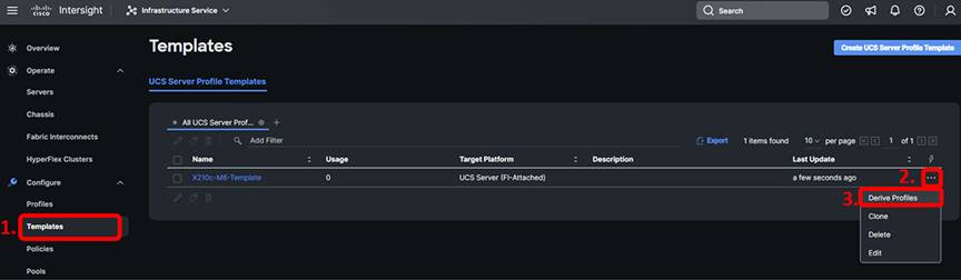
In Intersight, browse to Configure -> Templates.
From the table of templates, click the ellipses to the right of the template you created and choose Derive Profiles.
You can select server(s) to which to assign the derived profiles. Select all available servers applicable to this deployment and click “Next” to proceed.
Intersight lets you set a prefix and suffix for all derived profile names, and also lets you customize each one. You can also add a description and tags that will be applied to all profiles derived in this step (refer to the image below). Feel free to rename the profiles if you don’t like seeing “DERIVED” in the profile name. After customizing the steps in this section, click “Next.”
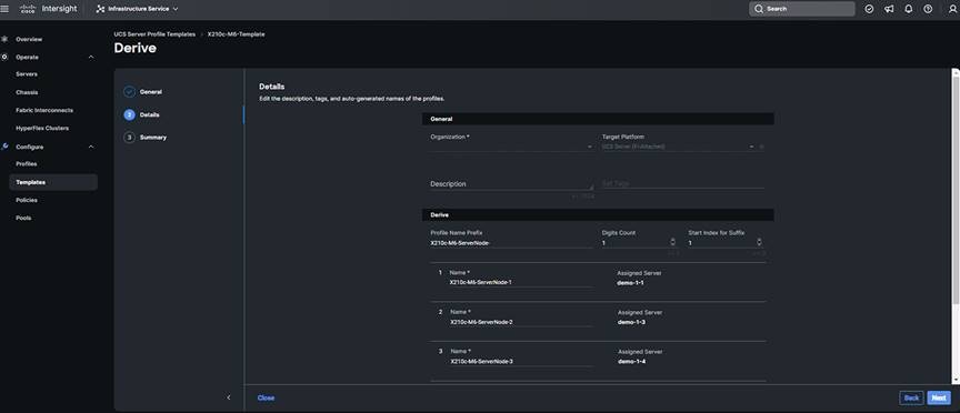
Click Derive.
The assignment process is immediate. The profiles are assigned to the servers, but no configuration changes happen yet.
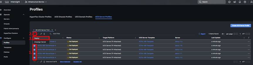
In Intersight, browse to Configure -> Profiles and select the UCS Server Profiles tab, and you will see that your profile(s) has been assigned to a server but shows a status of Not Deployed. You can select multiple profiles in this state and click the ellipses at the top of the table to deploy them all in bulk. When you deploy a profile, Intersight will create a Request that you can monitor. Every time you make a change to a profile or a policy associated with that profile, its state will change from Deployed to a state indicating changes that have not been pushed to the server, yet were made within Intersight. Each time, you will have to come back to this screen and Deploy the profile. This behavior is different from that of Cisco UCS Manager, so if you are unfamiliar, you can read more about the various states at: https://intersight.com/help/saas/features/servers/configure.
When ready to deploy the server profiles, click “Deploy” and then click “Deploy” again on the popup window:
Congratulations. You have assigned a profile to a server in Intersight. Now imagine an environment where you have multiple UCS domains. You can move that profile between any of those domains.
2.4 Optional: Install an operating system with a Software Repository
You can install an operating system by a traditional method of mapping the operating system install media through KVM and walking through the installation manually. Intersight provides the capability of automated operating-system installation. This section guides you through that process. If you prefer to install through KVM, proceed to the next section.
The automated OS installation requires a target for the OS to be installed to; see this document for more information related to creating and configuring local storage: https://www.cisco.com/c/en/us/support/docs/servers-unified-computing/ucs-infrastructure-ucs-manager-software/218160-configure-boot-from-local-storage-in-int.html.
Normally, the software repository used to install an operating system would be already configured. This section shows you how to set up an operating system image in the software repository and install an OS using that repository. Obviously, the process of automated OS installation for future OS installs will run faster after you do the initial work of setting up the repository.
In Intersight, you may be in the Infrastructure Service view. Change the view to System:
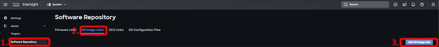
Once in the System view, navigate to Admin -> Software Repository, select the “OS Image Links” tab, then click the blue “Add OS Image Link” button.
Select either NFS, CIFS, or HTTP/S, add the file location (hover over the hint next to the field if you need an example), and choose the mount options “ro.” Click “Next.”
Add details for the operating system image. Provide the image any Name that you choose, but the vendor and version must match the contents of the ISO image. When finished providing the details, click the Add button.
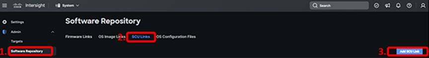
We also need to map the Server Configuration Utility (SCU) in the software repository. In the Software Repository section, click the “SCU Links” tab and click the “Add SCU Link”:
Select either NFS, CIFS, or HTTP/S, add the file location (hover over the hint next to the field if you need an example), and choose the mount options “ro.” Click “Next.”
Add details for the SCU image. Provide the image a Name, the Version, and the Supported Models. When finished providing the details, click the “Add” button.
Now that you have an OS image in your software repository, you can install that OS on your server(s). Make sure you are back in the Infrastructure Service view, then browse to Operate -> Servers.
Choose one or more servers on which to install the OS.
Click the ellipses at the top or bottom of the servers table and choose Install Operating System.
As you step through the wizard, you will see familiar screens like the one that lets you change your mind about which servers you want to affect. Step 2 of the process lets you choose from the images available in your local software repository.
Step 3 of the OS install lets you choose a config file. When selecting a valid config file, you will also see the option to provide variables such as IP addresses for each server on which you are installing an OS.
Choose either Static IP or DHCP and click Next.
Select the Server Configuration Utility that you added to the software repository. Click Next.
Choose the installation target (that is, which disk) for the operating system. Click Next.
On the final confirmation screen, choose Install. You can monitor the status of the installation the same way you monitored the status of firmware upgrades earlier in this guide.
Congratulations. You have installed an operating system using Intersight’s automated OS installation feature.
2.5 Optional: Install an operating system with KVM-attached virtual media
In this section, you will install an operating system using KVM-attached virtual media. Cisco Intersight supports OS install through a more automated process if desired. Additionally, it is unlikely you will have the OS images staged in the Intersight software repository.
In Intersight, browse to Operate -> Servers and locate the server on which you would like to attempt to install an OS through the KVM-attached virtual media.
Click the ellipses next to your server and select Launch vKVM.
In the tab that pops up for KVM, select Activate Virtual Devices from the Virtual Media menu. If you get an error message on this step, you likely did not attach the proper virtual media policy to the server profile. There should be a virtual media policy that enables virtual media. Go back and correct this problem. Do not forget to Deploy the profile after making changes.
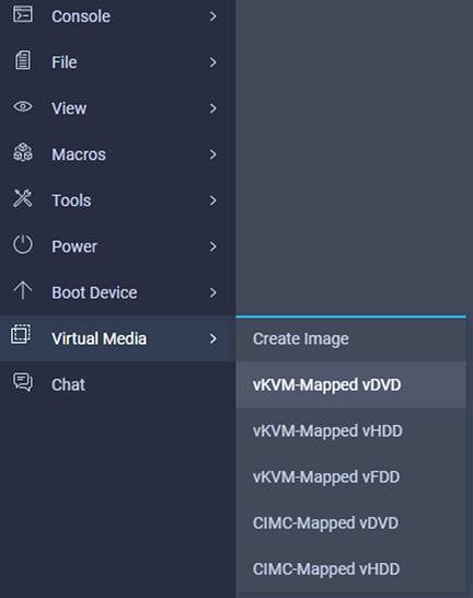
Hover over “Virtual Media” and select “vKVM-Mapped vDVD”:
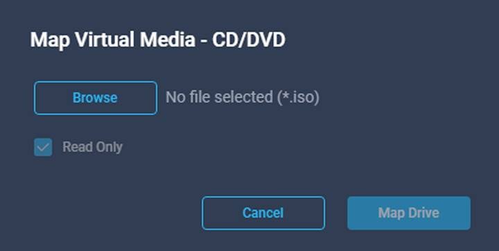
In the “Map Virtual Media – CD/DVD” popup, click “Browse” and navigate to the location of your iso, select the file, then click “Map Drive”:
Once attached, boot (or reboot) the server from the KVM window’s power options.
The remainder of the installation process should proceed, such as installing ESXi on any UCS server.
Cisco Intersight organizations
In this guide, you may have had access to a single organization within an Intersight account that has several organizations. When you started, your user role could have had visibility of only a single server. This construct is powerful in that it allowed you to create policies and profiles that others could neither see nor modify when using this Intersight account. Talk to your Cisco account team about using organizations effectively.
Every device that is claimed in Intersight is added to the default organization if no other Intersight organization has been created. When starting to use Intersight, it is tempting to use default as the one and only organization. As your environment grows, you may face RBAC challenges if attempting grant or restrict access to equipment based on roles or functions if everything is left in the default organization. Please review the organizations section of Intersight Help for more information: https://intersight.com/help/saas/resources/RBAC#organizations Intersight User Roles
In this guide, you may have had access to a built-in role (Device Technician) for claiming targets and a custom role for creating pools, policies, and profiles. The custom role could grant you administrative capabilities within one Intersight organization. Roles are a powerful construct that can provide an individual user or group of users the granular level of privileges needed. Talk to your Cisco account team about using roles effectively to enable team members.
4. Appendix and reference guides
Much of the content in this guide was copied directly from, repurposed, and/or included from several sources including but not limited to the following:
● Cisco UCS X9508 Server Chassis Installation Guide.
● Getting started with Intersight.
● Cisco Intersight Handbook.
● Cisco Intersight Help Center.
● Cisco UCS 6400 Series Fabric Interconnect Hardware Installation Guide.
● Cisco UCS 6500 Series Fabric Interconnect Hardware Installation Guide.
● Deploy Cisco UCS X210c Compute Node with Cisco Intersight Management Mode for VDI.
For more Intersight information such as browser, systems, and language support, please visit the Intersight Help Center:
● https://intersight.com/help/saas/faqs#browser_support_supported_systems_and_multi-language_support.