Deploy a High-Performance Standalone Oracle Database Solution: Oracle 19c on Cisco UCS X-Series
Available Languages
Bias-Free Language
The documentation set for this product strives to use bias-free language. For the purposes of this documentation set, bias-free is defined as language that does not imply discrimination based on age, disability, gender, racial identity, ethnic identity, sexual orientation, socioeconomic status, and intersectionality. Exceptions may be present in the documentation due to language that is hardcoded in the user interfaces of the product software, language used based on RFP documentation, or language that is used by a referenced third-party product. Learn more about how Cisco is using Inclusive Language.
Today, data is being stored, managed, and transmitted across a broad mix of IT computing infrastructures. Unique requirements, priorities, and challenges create continuous pressure for greater performance, reliability, manageability, and affordability. High-performance storage is essential to make applications run faster, achieve quicker response times, and analyze more data to extract meaningful information faster. As storage moves closer to the server, new opportunities for data center efficiency are arising.
The Cisco Unified Computing System™ (Cisco UCS®) X-Series is new modular computing system, configured and managed from the cloud. It is designed to meet the needs of modern applications and improve operational efficiency, agility, and scale through an adaptable, future-ready, modular design. The Cisco UCS X-Series is equipped with third-generation (3G) Intel Xeon scalable processors, and it supports Double Data Rate 4 (DDR4)-only memory modules or a mixture with Intel Optane Persistent Memory. The Cisco Intersight™ platform is a Software-as-a-Service (SaaS) infrastructure lifecycle management platform that delivers simplified configuration, deployment, maintenance, and support.
The Cisco UCS X-Series platform unites computing, networking, storage, and virtualization resources in a modular approach to reduce Total Cost of Ownership (TCO) and increase business agility. Ultra-low latency NonVolatile Memory express (NVMe) storage fully integrated into the Cisco UCS architecture enables servers to provide increased storage reliability and performance compared to spinning media. Bringing storage inside the server on a high-performance NVMe tier can also reduce application licensing costs, making local flash storage a powerful solution for delivering more capabilities on a smaller budget. And all these benefits are optimized more fully on the Cisco UCS platform than on any other server platform.
This document provides a reference architecture that illustrates the benefits of using the Cisco UCS X- Series Modular System. The X210c M6 blade with six intel P5600 NVMe Solid-State Drives (SSDs) demonstrates a high-performance transactional load on standalone Oracle Database 19c to provide a robust, resilient, and efficient infrastructure solution that can meet the demanding needs of businesses today.
Purpose of this document
This document discusses how you can achieve high I/O throughput with extremely low local NVMe storage access latency when using the Cisco UCS X-Series system for your enterprise-class standalone Oracle Database deployments.
Powered by the Cisco Intersight cloud-operations platform, the Cisco UCS X-Series enables the next- generation cloud-operated infrastructure that simplifies data center management. With this Cisco Intersight platform, you get all the benefits of SaaS delivery and the full lifecycle management of servers connected through the platform. The Cisco Intersight platform software delivers simplified configuration, deployment, maintenance, and support, resulting in the highest level of uptime as demanded by mission-critical database deployments.
The testing reported in this document illustrates how you can use a single-instance Oracle Database with the Cisco UCS X-Series and Intel P5600 NVMe drives as an enterprise-class solution to implement reliable and cost-effective Oracle Database solutions. This document demonstrates the scalability and performance aspect of the solution by running the benchmarking tool swingbench on an Online Transaction Processing (OLTP) database as a benchmark. The swingbench tool was used to populate the database and generate the I/O workload for this solution. The tests were run with varying numbers of users and read and update workload characteristics on a standalone Oracle Database 19c.
Benefits of Cisco UCS X-Series platform
You can use NVMe storage to eliminate the need for Storage-Area Networks (SANs) and Network-Attached Storage (NAS) or to augment existing shared-array infrastructure. Cisco UCS X-Series blade servers house 6 local NVMe drives. The Cisco UCS X-Series platform uses an advanced cooling methodology and zero- oversubscription CPU mapping to provide the highest levels of efficiency as well as best-in-class, consistent performance. You also can choose the amount of storage necessary to meet your workload needs.
This solution demonstrates the following benefits:
● Simplify with cloud-operated Infrastructure.
● Achieve flexibility, increased performance, and compatibility with industry standards.
● The solution is the most efficient methodology of handling thermal control for local storage.
● Achieve a high number of I/O Operations Per Second (IOPS) with low latency.
● Reduce business disruption and increase Oracle Database efficiency by deploying a pre-tested and validated solution.
With the Cisco Intersight platform, you get all the benefits of SaaS delivery and the full lifecycle management of servers connected through the platform.
The Oracle solution with the Cisco UCS X-Series and the Cisco Intersight platform delivers cloud-managed infrastructure on the latest Cisco UCS hardware. The Cisco Intersight cloud-management platform configures and manages the infrastructure. This section covers the solution requirements and design details.
Compute system connectivity
The Cisco UCS X9508 chassis is equipped with Cisco UCS 9108 25G Intelligent Fabric Modules (IFMs). Figure 1 shows a sample configuration of the Cisco UCS X9508 chassis connected to each Cisco UCS 6454 fabric interconnect using four 25 Gigabit Ethernet ports. If you need more bandwidth, you can connect all eight ports on the IFMs to each fabric interconnect. Cisco UCS 6454 fabric interconnects are connected to uplink switches, with connections configured as Virtual Port Channels (VPCs).
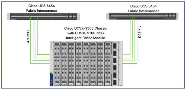
Sample configuration of Cisco UCS X9508 chassis connected to each Cisco UCS 6454
Table 1 shows the hardware and software the solution uses.
Table 1. Solution hardware and software
| Component |
Model |
Software version |
| Management |
2 x Cisco UCS 6454 Fabric Interconnects |
9.3(5)I42(1h) |
| Compute |
1 x Cisco UCS X210C-M6 Blade Server |
5.0(1b) |
| Processor |
Intel Xeon x86 Platinum 8358 CPU @ 2.60-GHz (2 x 32 cores CPU) |
|
| Memory |
16 x 32-GB DDR4 @ 3200-MHz clock speed |
|
| Adapters |
Cisco UCS Virtual Interface Card (VIC) 14425 and 4 x 25-GB modular LAN on Motherboard (mLOM) for X compute node |
|
| Storage |
6 x 3.2-TB 2.5-in. U.2 Intel P5600 NVMe high performance, medium endurance 2 x 240-GB M.2 Serial Attached Technology Attachment (SATA) SSD for OS boot drive |
NVMe drive - 2CV1C029 M.2 SSD drive - D3MC000 |
| Cisco software |
Cisco Intersight software |
|
| Software |
Red Hat Enterprise Linux 8.3 |
4.18.0-240.el8.x86_64 |
| Oracle Database 19c for Linux x86-64 |
19.10 |
|
| Oracle Database 19c Grid Infrastructure for Linux x86-64 |
19.10 |
|
| Swingbench |
2.5.0.971 |
|
| Silly Little Oracle Benchmark (SLOB) |
2.5.2.4 |
Cisco UCS X-Series Modular System overview
The Cisco UCS X-Series with Intersight is a modular system managed from the cloud. It is designed be shaped to meet the needs of modern applications and improve operational efficiency, agility, and scale through an adaptable, future-ready, modular design. The system simplifies your data center, adapting to the unpredictable needs of modern applications while also providing for traditional scale-out and enterprise workloads. It reduces the number of server types to maintain, helping improve operational efficiency and agility as it helps reduce complexity. Powered by the Cisco Intersight cloud-operations platform, it shifts your thinking from administrative details to business outcomes-with hybrid cloud infrastructure that is assembled from the cloud, shaped to your workloads, and continuously optimized.
Since we first delivered the Cisco UCS solution in 2009, our goal has been to simplify your data center. We pulled management out of servers and into the network. We simplified multiple networks into a single unified fabric. And we eliminated network layers in favor of a flat topology wrapped up into a single unified system. With the Cisco UCS X-Series Modular System we take that simplicity to the next level:
● Simplify with cloud-operated infrastructure: We move management from the network into the cloud so that you can respond at the speed and scale of your business and manage all of your infrastructure. Shape the Cisco UCS X-Series Modular System resources to workload requirements with the Cisco Intersight cloud-operations platform. Integrate third-party devices including storage from NetApp, Pure Storage, and Hitachi. Gain intelligent visualization, optimization, and orchestration for all of your applications and infrastructure. Automation promotes agility and consistency, helping you reduce time to market while lowering cost and risk.
● Simplify with an adaptable system designed for modern applications: Today's cloud-native, hybrid applications are inherently unpredictable. They are deployed and redeployed as part of an iterative DevOps practice. Requirements change often, and you need a system that doesn't lock you into one set of resources when you find that you need another. For hybrid applications and a range of traditional data center applications (refer to the Figure 2), you can consolidate onto a single platform that combines the density and efficiency of blade servers with the expandability of rack servers. The result: better performance, automation, and efficiency.
● Simplify with a system engineered for the future: Embrace emerging technology and reduce risk with a modular system designed to support future generations of processors, storage, nonvolatile memory, accelerators, and interconnects. Gone is the need to purchase, configure, maintain, power, and cool discrete management modules and servers. Cloud-based management is kept up-to-date automatically with a constant stream of new capabilities delivered by the Cisco Intersight SaaS model.
Hybrid and other data center applications
A single server type supporting a broader range of workloads means fewer different products to support, reduced training costs, and increased flexibility. The system supports workloads including the following:
● Virtualized workloads
● Private cloud
● Enterprise applications
● Database management systems
● Infrastructure applications
● Cloud-native applications
● In-memory databases
● Big data clusters
● Graphics processing unit (GPU)-AI/ML workloads
Cisco UCS X9508 chassis at-a-glance
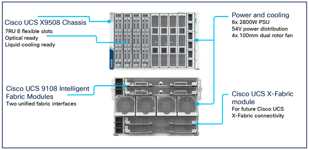
The Cisco UCS X-Series chassis is designed to be adaptable and flexible. The Cisco UCS X9508 chassis has only a power-distribution midplane. This design (Figure 3) presents fewer obstructions, for better airflow. For I/O connectivity, vertically oriented compute nodes intersect with horizontally oriented fabric modules, allowing the chassis to support future fabric innovations. The superior packaging of the Cisco UCS X9508 chassis enables larger compute nodes, thereby providing more space for actual computing components, such as memory, GPUs, drives, and accelerators. Improved airflow through the chassis enables support for higher-power components, and more space allows for future thermal solutions (such as liquid cooling) without limitations.
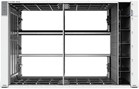
Cisco UCS X9508 Server chassis: Midplane-free design
The Cisco UCS X9508 is a 7-Rack-Unit (7RU) chassis offering 8 flexible slots. These slots can house a combination of compute nodes and a pool of future I/O resources that may include GPU accelerators, disk storage, and nonvolatile memory. At the top rear of the chassis are two IFMs that connect the chassis to upstream Cisco UCS 6400 Series Fabric Interconnects. At the bottom rear of the chassis are slots ready to house future X-Fabric modules that can flexibly connect the compute nodes with I/O devices. Six 2800- Watt (W) Power Supply Units (PSUs) provide 54-Volt (V) power to the chassis with N, N+1, and N+N redundancy. A higher voltage allows efficient power delivery with less copper and reduced power loss.
Efficient 100-mm dual counter-rotating fans deliver industry-leading airflow and power efficiency, and optimized thermal algorithms enable you to use different cooling modes to best support your environment.
Cisco UCS 9108 25G Intelligent Fabric Module
For the Cisco UCS X9508 chassis, the network connectivity is provided by a pair of Cisco UCS 9108 25G IFMs (Figure 4). Like the fabric extenders used in the Cisco UCS 5108 Blade Server chassis, these modules carry all network traffic to a pair of Cisco UCS 6400 Series Fabric Interconnects. IFMs also host the Chassis Management Controller (CMC) for chassis management. In contrast to systems with fixed networking components, the Cisco UCS X9508 uses a midplane-free design. This design enables easy upgrades to new networking technologies as they emerge and straightforward accommodation of new network speeds and technologies in the future.
![]()
Cisco UCS 9108 25G Intelligent Fabric Module
Each IFM supports eight 25-Gbps uplink ports for connecting the Cisco UCS X9508 chassis to the fabric interconnects and thirty-two 25-Gbps server ports for the eight compute nodes. IFM server ports can provide up to 200 Gbps of unified fabric connectivity per compute node across the two IFMs. The uplink ports connect the chassis to the Cisco UCS fabric interconnects, providing up to 400-Gbps connectivity across the two IFMs. The unified fabric carries management, virtual machine, and Fibre Channel over Ethernet (FCoE) traffic to the fabric interconnects. There, management traffic is routed to the Cisco Intersight cloud-operations platform, FCoE traffic is forwarded to the native Fibre Channel interfaces through unified ports on the fabric interconnects (to Cisco MDS 9000 Family switches), and data Ethernet traffic is forwarded upstream to the data center network (through Cisco Nexus® Family switches).
Cisco UCS X210c M6 Compute Node
The Cisco UCS X210c M6 Compute Node is the first computing device to integrate into the Cisco UCS X- Series Modular System. Up to eight compute nodes can reside in the 7RU Cisco UCS X9508 chassis, offering one of the highest densities of compute, I/O, and storage per rack unit in the industry (Figure 5).
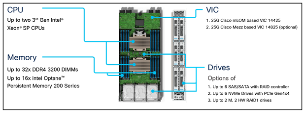
Cisco UCS X210c M6 Compute Node
Cisco UCS VICs
Cisco UCS X210c M6 Compute Nodes support two Cisco fourth-generation VICs.
Cisco UCS VIC 14425
The Cisco UCS VIC 14425 (Figure 6) fits the mLOM slot in the Cisco X210c Compute Node and enables up to 50 Gbps of unified fabric connectivity to each of the chassis IFMs, for a total of 100 Gbps of connectivity per server. Cisco UCS VIC 14425 connectivity to the IFM and to the fabric interconnects is delivered through four 25-Gbps connections, which are configured automatically as two 50-Gbps port channels. The Cisco UCS VIC 14425 supports 256 virtual interfaces (both Fibre Channel and Ethernet) along with the latest networking innovations such as Non-Volatile Memory Express over Fabrics (NVMeoF) over RDMA (ROCEv2), Virtual Extensible LAN (VXLAN) and Network Virtualization Generic Routing Encapsulation (NVGRE) offload, and so on.
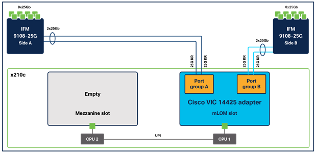
Single Cisco UCS VIC 14425 in Cisco UCS X210c M6
Cisco UCS VIC 14825
The optional Cisco UCS VIC 14825 (Figure 7) fits the mezzanine slot on the server. A bridge card (UCSX- V4-BRIDGE) extends two 50 Gbps of network connections of this VIC to the mLOM slot and out through the IFM connectors of the mLOM, bringing the total bandwidth to 100 Gbps per fabric, for a total bandwidth of 200 Gbps per server.
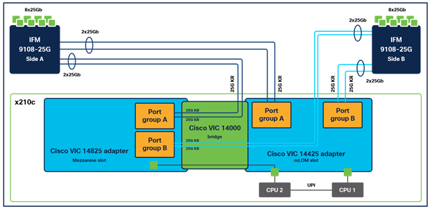
Cisco VIC 14425 and 14825 in Cisco UCS X210c M6
Cisco UCS 6400 Series Fabric Interconnect
The Cisco UCS fabric interconnects provide a single point for connectivity and management for the entire Cisco UCS deployment. Typically deployed as an active-active pair, fabric interconnects of the system integrate all components into a single, highly available management domain that the Cisco UCS Manager or Cisco Intersight platform controls. Cisco UCS fabric interconnects provide a single unified fabric for the system, with low-latency, lossless, cut-through switching that supports LAN, Storage-Area Network (SAN), and management traffic using a single set of cables.
![]()
Cisco UCS 6454 Fabric Interconnect
The Cisco UCS 6454 Fabric Interconnect used in the current design is a 54-port fabric interconnect (Figure 8). This 1RU device includes 28 x 10-/25-Gbps Ethernet ports, 4 x 1-/10-/25-Gbps Ethernet ports, 6 x 40-/100-Gbps Ethernet uplink ports, and 16 unified ports that can support 10-/25-Gigabit Ethernet or 8- /16-/32-Gbps Fibre Channel, depending on the Small Form-Factor Pluggable (SFP) design.
Note: To support the Cisco UCS X-Series, the fabric interconnects must be configured in Cisco Intersight managed mode This option replaces the local management with Cisco Intersight cloud- or appliance- based management.
Cisco Intersight Platform
The Cisco Intersight platform is a SaaS infrastructure lifecycle management platform that delivers simplified configuration, deployment, maintenance, and support (Figure 9). This platform is designed to be modular, so you can adopt services based on your individual requirements. It significantly simplifies IT operations by bridging applications with infrastructure, providing visibility and management from bare-metal servers and hypervisors to serverless applications, thereby reducing costs and mitigating risk. This unified SaaS platform uses a unified Open API design that natively integrates with third-party platforms and tools.
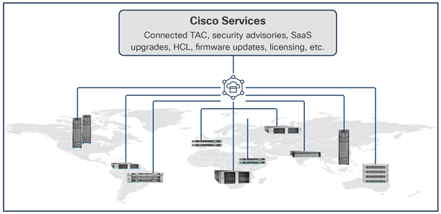
Cisco Intersight overview
The main benefits of Cisco Intersight infrastructure services follow:
● Simplify daily operations by automating many daily manual tasks.
● Combine the convenience of a SaaS platform with the capability to connect from anywhere and manage infrastructure through a browser or mobile app.
● Stay ahead of problems and accelerate trouble resolution through advanced support capabilities.
● Gain global visibility of infrastructure health and status along with advanced management and support capabilities.
● Upgrade to add workload optimization and Kubernetes services when needed.
Cisco Intersight Virtual Appliance and Private Virtual Appliance
In addition to the SaaS deployment model running on Intersight.com, you can purchase on-premises options separately. The Cisco Intersight Virtual Appliance and Cisco Intersight Private Virtual Appliance are available for organizations that have additional data locality or security requirements for managing systems. The Cisco Intersight Virtual Appliance delivers the management features of the Cisco Intersight platform in an easy-to-deploy VMware Open Virtualization Appliance (OVA) or Microsoft Hyper-V Server virtual machine that allows you to control the system details that leave your premises. The Cisco Intersight Private Virtual Appliance is provided in a form factor designed specifically for users who operate in disconnected (air gap) environments. The Private Virtual Appliance requires no connection to public networks or back to Cisco to operate.
Cisco Intersight Assist
Cisco Intersight Assist helps you add endpoint devices to the Cisco Intersight platform. A data center could have multiple devices that do not connect directly with the platform. Any device that the Cisco Intersight platform supports, but does not connect directly with, needs a connection mechanism. Cisco Intersight Assist provides it.
Cisco Intersight Assist is available within the Cisco Intersight Virtual Appliance, which is distributed as a deployable virtual machine contained within an OVA file format.
Licensing requirements
The Cisco Intersight platform uses a subscription-based license with multiple tiers. You can purchase a subscription duration of 1, 3, or 5 years and choose the required Cisco UCS server volume tier for the selected subscription duration. Each Cisco® endpoint automatically includes a Cisco Intersight Base license at no additional cost when you access the Cisco Intersight portal and claim a device. You can purchase any of the following higher-tier Cisco Intersight licenses using the Cisco ordering tool:
● Cisco Intersight Essentials: Essentials includes all the functions of the Base license plus additional features, including Cisco UCS Central software and Cisco Integrated Management Controller (IMC) supervisor entitlement, a policy-based configuration with server profiles, firmware management, and evaluation of compatibility with the Cisco Hardware Compatibility List (HCL).
● Cisco Intersight Advantage: Advantage offers all the features and functions of the Base and Essentials tiers and storage widgets and cross-domain inventory correlation across compute, storage, and virtual environments (VMware ESXi). It also includes OS installation for supported Cisco UCS platforms.
● Cisco Intersight Premier: In addition to all the functions provided with the Advantage tier, Premier includes full subscription entitlement for Cisco Intersight Orchestrator, which provides orchestration across Cisco UCS and third-party systems.
Servers in Cisco Intersight managed mode require at least the Essentials license[1].
For more information about the features provided in the various licensing tiers,
Please visit https://intersight.com/help/getting_started#licensing_requirements.
Intel P5600 Drive
Intel P5600 Drive is designed to meet today's increasingly I/O-intensive requirements across a wide range of workloads while improving IT efficiency. Architected with 96-layer TLC, Intel 3D NAND Technology, the Intel SSD D7-P5600 Series offers optimized performance and capacity for all-TLC arrays and the drivers are designed to advance IT efficiency and data security. The Intel SSD D7-P5600 Series includes an all-new Intel PCIe* Gen4 controller and firmware that bring low latency, enhanced management capabilities, scalability, and critical new NVMe* features for enterprise and cloud environments. Available in the U.2 15-mm form factor, these SSDs offer 1.92, 3.84, and 7.68 TB at 1 Drive Write Per Day (DWPD) and 1.6, 3.2, and 6.4 TB at 3 DWPD.
Unlock the value of stored data
The Intel SSD D7-P5600 Series delivers predictably fast, high performance and can greatly accelerate all- TLC storage arrays. Compared to previous-generation Intel SSDs, the performance-optimized D7-P5600 brings up to 44 percent higher random mixed-workload performance. These drives also offer improvements to tail latencies, including up to 80 percent lower 4-KB Random Read Quality of Service (QoS) for 99.99999 percent of transactions.
Advanced features for drive performance, IT efficiency, and data security
The Intel SSD D7-P5600 Series includes numerous firmware enhancements designed specifically to improve IT efficiency and data security in an increasingly data-centric world.
● Dynamic namespace management delivers the flexibility to enable more users and scale deployment.
● Additional security features such as TCG Opal 2.0 and a built-in AES-XTS 256-bit encryption engine, which are required by some secure platforms, are included.
● Enhanced SMART monitoring reports drive health status without disrupting I/O data flow using an in-band mechanism and out-of-band access.
● Telemetry 2.0 makes a wide range of stored data accessible and includes intelligent error tracking and logging, thereby increasing the reliability of finding and mitigating problems and adding support for accelerated qualification cycles-all of which can result in increased IT efficiency.
● Optimized TRIM architecture now runs as a background process without interference to workloads, improving performance and QoS during concurrent TRIM processes. The TRIM process is improved for high-density drives, with reduced write amplification that helps drives meet their endurance goal.
A Power-Loss Imminent (PLI) protection scheme with built-in self-testing guards against data loss if system power is suddenly lost. Coupled with and end-to-end data path protection scheme, PLI features also enable ease of deployment into resilient data centers where data corruption from system-level glitches is not tolerated.
It is beyond the scope of this document to include all the detailed steps for this solution configuration. Please refer to this link for more detailed configuration reference:
https://www.cisco.com/c/en/us/products/collateral/servers-unified-computing/ucs-x-series-modular-system/ucs-x-series-quick-start-guide.html
Following are the high-level steps to configure the Cisco UCS 6454 Fabric Interconnects, Cisco UCS X210c M6 Server, and Oracle Database 19c setup:
1. Configure the fabric interconnects for Cisco Intersight management.
◦ Configure the first fabric interconnect for Cisco Intersight management.
◦ Configure the second fabric interconnect for Cisco Intersight management.
2. Claim the fabric interconnects in the Cisco Intersight platform.
3. Upgrade the fabric interconnect firmware.
4. Create a UCS domain profile.
5. Verify the discovered chassis.
6. Create a chassis profile.
7. Create UCS server profiles.
8. Assign profiles to servers.
9. Install an operating system with the software repository.
Configure fabric interconnects for Cisco Intersight management
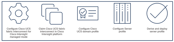
You can connect the Cisco UCS X9508 chassis to Cisco UCS 6400 Series Fabric Interconnects to provide a single point of connectivity for the system. When supporting the Cisco UCS X-Series, the fabric interconnects run in Cisco Intersight managed mode, which standardizes policy and operation management for the Cisco UCS X-Series. The compute nodes in the Cisco UCS X-Series are configured using server profiles defined in the Cisco Intersight platform. These server profiles derive all the server characteristics from various policies and templates. At a high level, configuring Cisco UCS using Cisco Intersight managed mode consists of these steps:.
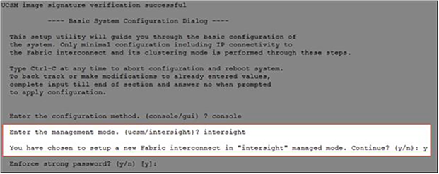
During the initial configuration, for the management mode the configuration wizard enables you to choose whether to manage the fabric interconnect through Cisco UCS Manager or the Cisco Intersight platform. You can switch the management mode for the fabric interconnects between the Cisco Intersight platform and Cisco UCS Manager at any time; however, Cisco UCS fabric interconnects must be set up in Cisco Intersight managed mode to configure the Cisco UCS X-Series system. The following screenshot shows the dialog box during initial configuration of the Cisco UCS fabric interconnects to set up Cisco Intersight managed mode.
Configure first fabric interconnect for Cisco Intersight management
You will be asked whether or not to enforce strong passwords. Obviously, strong passwords are encouraged. For the first fabric switch, choose A and name the system and enter the IP address for FI-A. Then enter the netmask for the management network, default gateway, IP address of the Domain Name System (DNS) servers, and the default domain name according to your environment. Finally, confirm all of your settings and then press yes to continue. It will take several minutes for the fabric interconnect to reboot. Proceed to the next section to configure the second fabric interconnect.
Configure second fabric interconnect for Cisco Intersight management
You may need to hit the Enter key to wake up the console for FI-B. If you see nothing on the screen, the fabric interconnect might be in the mode where it is waiting for you to either configure it from the Graphical User Interface (GUI) or press CTRL-c to interrupt the process. Just like you did for the FI-A setup, here FI-B should detect that its peer (FI-A) is already configured and will ask if it should attempt to join that cluster. Type y and hit Enter. Enter the password you used for FI-A, provide FI-B with an IP address, and type yes to save the configuration and restart the fabric interconnect.
After configuring both fabric interconnects in Cisco Intersight managed mode, it will take several minutes for the FI to reboot. Proceed to the next section to claim the fabric interconnect pair into the Cisco Intersight platform.
Claim fabric interconnects in Cisco Intersight platform
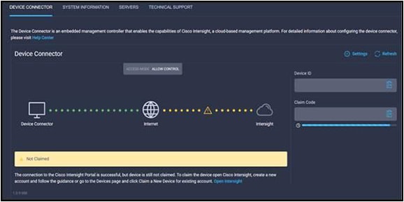
For this step, using one of the supported browsers, connect the IP address of fabric interconnect A. Ensure that Secure HTTP (HTTPS) is used or you will not be able to connect to the device console, and then use the credentials you configured earlier during fabric interconnect setup to log in. Go the Device Connector tab. If there is an error on this page saying "Some unknown internal error has occurred", it is likely because this domain has been claimed in Cisco Intersight already. Please click the Refresh button in the device connector view, but if the problem persists, reach out to the Cisco Technical Assistance Center (TAC) to address this problem. If instead you see a screen that shows that the fabric interconnect can connect to the Cisco Intersight platform but is not yet claimed, then proceed to the next step.
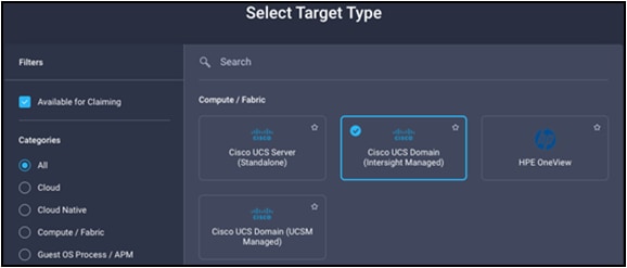
Browse to intersight.com from your computer. Use Cisco Intersight credentials for an account that has at least the device technician role. The roles device technician and device administrator allow you to claim and un claim devices but do little else. Click the blue Claim Target button in the Cisco Intersight platform. For target type, select Cisco UCS Domain (Intersight Managed) as follows and click the Start button.
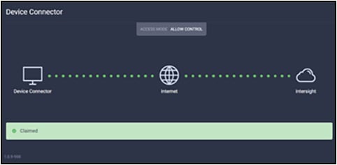
You'll need the device ID and claim code from the device console. Try copying those values into the Cisco Intersight platform. Click the blue Claim button. Shortly after the claim succeeds, the fabric interconnect device connector should show a status of Claimed:
Note: If your credentials don't have that privilege level, please reach out to someone within the organization with Account Administrator credentials.
After the domain is claimed to the Cisco Intersight platform, all configuration of servers, chassis, and fabric interconnects is initiated with the Cisco Intersight platform. For more information about Cisco Intersight managed domains, refer to the Cisco Intersight Managed Mode Configuration Guide at: https://intersight.com/help/saas/resources/cisco_intersight_managed_mode_configuration.
Upgrade fabric interconnect firmware
Before discovering what hardware is connected to the fabric interconnects, you must upgrade the fabric interconnect firmware to the latest recommended version. In the Cisco Intersight platform, browse to OPERATE > Fabric Interconnects. Click the three dots at the end of the row for either of the fabric interconnects and select Upgrade Firmware. Click Start"to bypass the first screen of the firmware upgrade. Step 1 of the upgrade shows you the current running version for each fabric interconnect. Click Next.
Step 2 of the upgrade allows you to select a different version of firmware. Fabric interconnects in this state (with no discovered chassis) do not need to evacuate server traffic. You must select Advanced Mode and uncheck Fabric Interconnect Traffic Evacuation as shown in the following screenshot. Do not do this for domains with discovered chassis.
Step 3 of the upgrade is simply a confirmation screen that should show both fabric interconnects with their current firmware version and an icon showing the intended firmware version, also shown in the following screenshot. Click Upgrade.
The Intersight Requests icon will help you keep track of long-running tasks such as firmware updates. You will be required to confirm that it is okay to start upgrading the first fabric interconnect, also as shown in the following screenshot. Click the Continue button and click Continue again on the popup. At this point, the firmware has been downloaded and you just approved the process to begin updating the firmware on the first fabric interconnect.
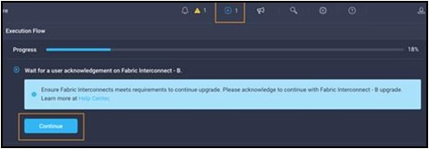
It will take about 15 to 20 minutes for the first fabric interconnect to complete its upgrade. You will be required to confirm that it is okay to start upgrading the second fabric interconnect, much like you did in the previous step. Watch for the spinning blue circle to change to a circle with an arrow to indicate that your action is required. Click Continue and click Continue again on the popup. It will take about 15 to 20 minutes for the second fabric interconnect to complete its upgrade. If you browse away from the firmware upgrade status, you can always get back to it by clicking the spinning blue circle in the Intersight task bar to see current or completed tasks. Browse to OPERATE -> Fabric Interconnects to confirm that both fabric interconnects are now running the correct version of firmware as used in this solution.
Create a Cisco UCS domain profile
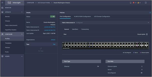
The Cisco Intersight platform cannot discover any hardware connected to the fabric interconnects until its ports are configured, and that is done through a domain profile. You can create each of the policies the profile will use before you create it, or you can create the policies while creating the profile. A Cisco UCS domain profile configures a fabric interconnect pair through reusable policies, allows configuration of the ports and port channels, and configures the Virtual LANs (VLANs) to be used in the network. It defines the characteristics of and configures the ports on the fabric interconnects. You can assign one Cisco UCS domain profile to one fabric interconnect domain, and the Cisco Intersight platform supports the attachment of one port policy per Cisco UCS domain profile.
Some of the characteristics of the Cisco UCS domain profile in the Oracle environment follow:
● A single domain profile is created for a pair of Cisco UCS fabric interconnects.
● Unique port policies are defined for the two fabric interconnects.
● The VLAN configuration policy is common to the fabric interconnect pair because both fabric interconnects are configured for the same set of VLANs.
● The Network Time Protocol (NTP), network connectivity, and system QoS policies are common to the fabric interconnect pair.
After the Cisco UCS domain profile has been successfully created and deployed, the policies, including the port policies, are pushed to the Cisco UCS fabric interconnects. You can easily clone the Cisco UCS domain profile to install additional Cisco UCS systems. When you clone the Cisco UCS domain profile, the new Cisco UCS domains use the existing policies for consistent deployment of additional Cisco UCS systems at scale:
Verify discovered chassis
The Cisco UCS X9508 chassis and Cisco UCS X210c M6 Compute Nodes are automatically discovered when the ports are successfully configured using the domain profile:
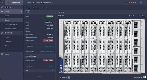
Cisco UCS X9508 Server chassis (front view)
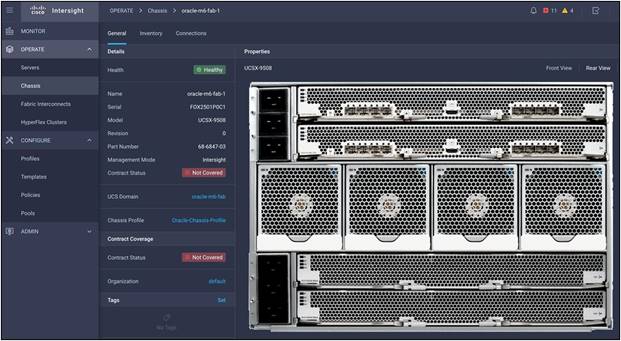
Cisco UCS X9508 Server chassis (rear view)
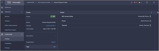
Create a chassis profile
For this solution, we have configured one chassis profile with 3 Policies - An IMC access policy, a power policy, and a thermal policy.
Create Cisco UCS server profiles
A server profile template enables resource management by simplifying policy alignment and server configuration. A server profile template is created using the server profile template wizard. The wizard groups the server policies into the following four categories to provide a quick summary view of the policies that are attached to a profile:
● Compute policies: Basic I/O System (BIOS), boot order, and virtual media policies.
● Network policies: Adapter configuration and LAN connectivity policies.
◦ The LAN connectivity policy requires you to create an Ethernet network policy, an Ethernet adapter policy, and an Ethernet QoS policy.
● Storage policies: For using the configured local drives.
Some of the characteristics of the server profile template for this Oracle Solution include:
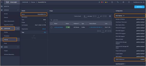
● BIOS policy with a Volume Management Device (VMD) enabled: We configured a BIOS policy and "enabled" the VMD feature to support hot-plug and surprise removal NVMe SSD functions.
Note: The Intel VMD is an Intel Xeon scalable processor feature that enables direct control and management of NVMe SSDs from the PCIe bus without additional hardware adaptors. This function allows a seamless transition to NVMe storage while providing support for hot-plug removal of the NVMe SSD and limiting the downtime of critical infrastructure.
For more information, please visit:
https://www.intel.com/content/www/us/en/architecture-and-technology/intel-volume-management- device-overview.html.
● The boot-order policy defines the Unified Extensible Firmware Interface (UEFI) mode to enable virtual media (KVM mapper DVD) and local disk devices.
● The IMC access policy defines the management IP address pool for KVM access.
● The local user policy enables KVM-based user access.
To enable the VMD feature with the BIOS policy, go to Configure > Policies > and select Create Policy and then select the policy type as BIOS and give a policy name such as "Oracle-BIOS-19c". Click Next and in the Boot Options > change VMD Enablement from "platform-default" to "enabled" and click Create to configure a BIOS policy for this solution. For this solution, we have created a BIOS policy:
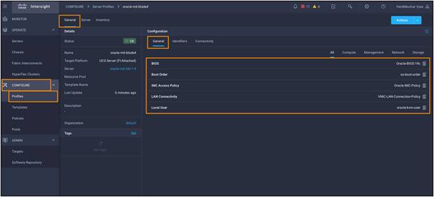
We have configured a server profile with the BIOS policy, local boot order policy, IMC access policy, vNIC LAN connectivity policy, and local user policy:
Assign profiles to servers
The Cisco Intersight server profile allows you to deploy server configurations directly on the compute nodes based on polices defined in the server profile template. After a server profile template has been successfully created, you can derive the policies from the template and associate them with the Cisco UCS X210c M6 compute nodes. On successful deployment of the server profile, the Cisco UCS X210c M6 compute nodes are configured with parameters defined in the server profile and can boot from a Redundant Array of Independent Disks (RAID) 5 system or, optionally, from the RAID 1 configured dual M.2 drives.
Install an operating system with software repository
You can install an operating system by a traditional method of mapping the operating system install media using KVM and walking through the installation manually. The Cisco Intersight platform enables automated operating system installation. This section guides you through that process.
For this Oracle solution, we have installed and configured Red Hat Enterprise 8.3 on one of the X210 M6 blades. After installing the RHEL OS, we configured Oracle 19c operating system prerequisites on this node to install Oracle Database 19c software. To configure the operating system prerequisites using RPM for Oracle 19c software on the node, install the "oracle-database-preinstall-19c" rpm package. You can also download the required packages at https://public-yum.oracle.com/oracle-linux-8.html.
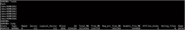
For this solution, we used six front local Intel P5600 3.2-TB NVMe SSDs. After OS installation, verify all NVMe devices detected on the OS native path:
Oracle Grid Infrastructure and Database 19c configuration
Before installing Oracle Database, verify that all the prerequisites are configured on Oracle Linux 8.3. For more information, please refer to:
https://docs.oracle.com/en/database/oracle/oracle-database/19/cwlin/index.html.
https://docs.oracle.com/en/database/oracle/oracle-database/19/ladbi/index.html.
For this solution, we installed and configured Oracle Grid Infrastructure and Oracle Database 19c software for a standalone server on the Cisco UCS X210c M6. The details of Oracle Grid Infrastructure and Oracle Database installation are beyond the scope of this document. You can refer to the Oracle installation documentation for specific installation instructions for your environment. For more details, please refer to the following links to install Oracle Grid Infrastructure 19c for Standalone Cluster:
https://docs.oracle.com/en/database/oracle/oracle-database/19/cwadd/index.html.
https://docs.oracle.com/en/database/oracle/oracle-database/19/ostmg/index.html.
The solution described here has 6 NVMe drives, each having 3.2-TB size of capacity.
● After discovering NVMe devices, locate the wwn id of each NVMe disk:
[oracle@ora-blade1 ~]$ /usr/bin/lsblk -o wwn /dev/nvme1n1 WWN
eui.01000000000000005cd2e4cb74385351
● Configure UDEV to assign permissions to enable Oracle user to enable read/write privileges on these devices. Configure UDEV rules:
[oracle@ora-blade1 ~]$ cat /etc/udev/rules.d/80-nvme.rules
#Generated by create_udevrules.
KERNEL=="nvme[0-9]*n[0-9]*", ENV{DEVTYPE}=="disk", ENV{ID_WWN}=="eui.01000000000000005cd2e4a074385351", SYMLINK+="ASMDISK1", GROUP:="oinstall", OWNER:="oracle", MODE:="660"
KERNEL=="nvme[0-9]*n[0-9]*", ENV{DEVTYPE}=="disk", ENV{ID_WWN}=="eui.01000000000000005cd2e4cb74385351", SYMLINK+="ASMDISK2", GROUP:="oinstall", OWNER:="oracle", MODE:="660"
KERNEL=="nvme[0-9]*n[0-9]*", ENV{DEVTYPE}=="disk", ENV{ID_WWN}=="eui.01000000000000005cd2e4c07c385351", SYMLINK+="ASMDISK3", GROUP:="oinstall", OWNER:="oracle", MODE:="660"
KERNEL=="nvme[0-9]*n[0-9]*", ENV{DEVTYPE}=="disk", ENV{ID_WWN}=="eui.01000000000000005cd2e49a7c385351", SYMLINK+="ASMDISK4", GROUP:="oinstall", OWNER:="oracle", MODE:="660"
KERNEL=="nvme[0-9]*n[0-9]*", ENV{DEVTYPE}=="disk", ENV{ID_WWN}=="eui.01000000000000005cd2e4d37c385351", SYMLINK+="ASMDISK5", GROUP:="oinstall", OWNER:="oracle", MODE:="660"
KERNEL=="nvme[0-9]*n[0-9]*", ENV{DEVTYPE}=="disk", ENV{ID_WWN}=="eui.01000000000000005cd2e4b9db625351", SYMLINK+="ASMDISK6", GROUP:="oinstall", OWNER:="oracle", MODE:="660"
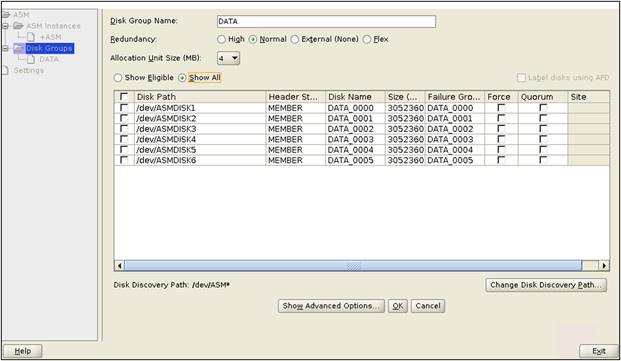
● We configured one disk group as "DATA" with redundancy type as "Normal" with all the drives to store all the database files.
● We configured the Oracle Grid Infrastructure and Oracle Database with normal redundancy on these six NVMe SSDs; we created "DATA" ASM Disk group to store database files.
After we configured the Oracle ASM disk group, we installed Oracle Grid Infrastructure and Oracle Database 19c standalone software on this server. Oracle binaries are installed on the local disk of the server. The data file and redo log files reside in the Oracle ASM disk group created on these NVMe drives.
This section discusses various test scenarios that evaluate the performance of the Cisco X210c M6 Server with local NVMe SSDs. It's a common practice to evaluate the system baseline performance before deploying any database application. System baseline performance testing is performed using common I/O calibration tools such as Linux FIO. These tools can generate I/O patterns that mimic the type of I/O operations that Oracle databases perform.
Methodology and testing tool
A first step in evaluating storage performance is the use of a synthetic workload generator or benchmarking tool that generates an application-centric I/O load profile while measuring storage performance. Simplicity, reproducibility with ease, and scalability are the primary reasons for using a synthetic generator instead of setting up and testing the actual application, at least as the first step. Recently. FIO has become the most popular choice for I/O profiling and characterization. Additionally, FIO is easy-to-obtain, simple-to-use, and viable for Linux environments, and it supports asynchronous I/O to mimic modern applications behavior, particularly to avoid I/O distribution across CPU cores and avoid serialization.
Running the test
In our tests, we used the FIO load generator to exercise 6 local Intel 5600 NVME disks with 3.2 TB each. Even though it is a single instance of Oracle Database running on a single blade server, we decided to run performance tests on all 8 fully populated X210c blades simultaneously so we can ensure performance:
● No impact on an individual blade server performance because of power and cooling.
● No slot dependency; all blades achieve identical performance irrespective of slot inside the chassis.
Test criteria
● Precondition all disks by writing random data patterns.
● Observe and validate sustained IOPS and performance over 30 minutes, 1 hour, and 4 hours with average and 90th percentile sub-millisecond latency for various read/write ratios. Multiple runs for each iteration were conducted, and careful analysis was done to verify the data consistency.
● Generate reproducible results with minimal parameter changes while mimicking application behavior. In other words, we could generate slightly higher numbers, but the goal is not to generate peak benchmark numbers with a lot of tweaking and variables. For each test, appropriate FIO I/O, depth, and number of jobs were selected along with asynchronous I/O as a parameter.
Test results
Results are shown in Figure 10.
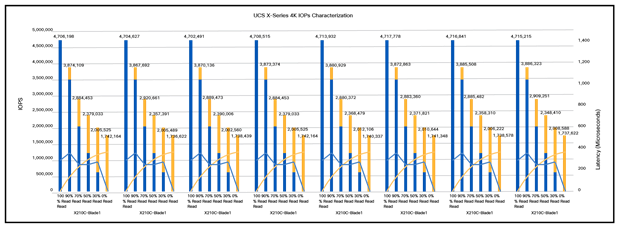
Test results
Observation
● Each blade server generated approximately 4.7 million sustained IOPS at 100-percent reads with a total around 37+ million IOPS at nearly 500-microseconds latency.
● We saw near identical I/O behavior on all 8 blade servers.
● The test used very low (system) CPU to generate I/O load, and that means plenty of CPU cycles were available for workloads to process data.
● The likely result is significant power and cooling savings.
SLOB performance test
The Silly Little Oracle Benchmark (SLOB) is a toolkit for generating and testing I/O through an Oracle database. SLOB is very effective in testing the I/O subsystem with genuine Oracle SGA-buffered physical I/O. SLOB supports testing physical random single-block reads (db file sequential read) and random single-block writes (DataBase Writer [DBWR] flushing capability). SLOB issues single-block reads for the read workload that are generally 8K (as the database block size was 8K).
For testing the SLOB workload, we created one non-container database as SLOB on one of the blade servers. For a SLOB database, we created one disk group as "DATA" to store the "data" and "redolog" files for the SLOB database. The DATA disk group was created with all 6 NVMe local disks, and we loaded around 2 TB of SLOB schema to generate Online Transition Processing (OLTP) workload. This single- istance database server applied the workload to Oracle Database, log, and temporary files. The following tests were performed, and various metrics such as IOPs and latency were captured along with Oracle AWR reports for each test scenario.
User scalability test
SLOB2 was configured to run against this single-instance Oracle Database node, and the concurrent users were spread on this node. We tested the environment by increasing the number of Oracle users in the database from a minimum of 64 users up to a maximum of This single-instance node had 512 users. At each load point we verified that the storage system and the server node could maintain steady-state behavior without any problems. We also ensured that there were no bottlenecks on this server node or networking systems across this chassis.
The user scalability test was performed with 64, 128, 192, 256, 384, and 512 users on a single-instance Oracle Database node by varying the read/write ratio as explained here:
● Varying workloads
◦ 100% read (0% update)
◦ 90% read (10% update)
◦ 70% read (30% update)
◦ 50% read (50% update)
Table 2 lists the total number of IOPS (both read and write) available for the user scalability test when run with 64, 128, 192, 256, 384, and 512 users on the SLOB database.
Table 2. Total number of IOPS available for users
| Users |
Read/write % (100-0) |
Read/write % (90-10) |
Read/write % (70-30) |
Read/write % (50-50) |
| 64 |
539,644 |
538,604 |
572,136 |
585,691 |
| 128 |
976,233 |
909,865 |
915,565 |
843,080 |
| 192 |
1,331,062 |
1,176,907 |
1,062,081 |
957,565 |
| 256 |
1,557,914 |
1,456,991 |
1,162,082 |
979,079 |
| 384 |
2,057,271 |
1,791,891 |
1,196,425 |
952,353 |
| 512 |
2,372,837 |
1,915,984 |
1,165,473 |
935,922 |
Figures 11 and 12 demonstrate the total number of IOPS while running a SLOB workload for various concurrent users for each test scenario.
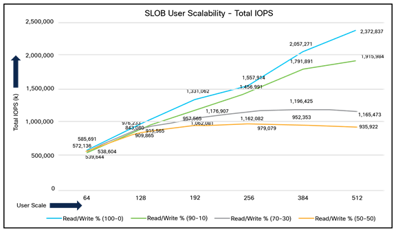
Total number of IOPS for test scenarios
The figure shows the linear scalability with increased numbers of users and similar IOPS from 64 users to 512 users with 100-percent read/write, 90-/10-percent read/write, 70/-30-percent read/write, and 50-/50-percent read/writes. The following screenshot shows the CPU usage and database read+write per second for the 512-user scale test.
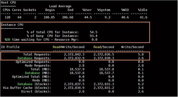
Figure 12 illustrates the latency exhibited by the local storage across different workloads. All the workloads experienced less than 1 millisecond latency, and it varies based on the workloads. As expected, the 50- percent read (50-percent update) test exhibited higher latencies as the user counts increased.
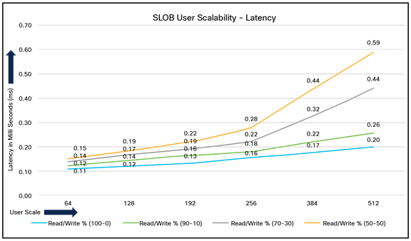
Latency by local storage across different workloads
Swingbench performance test
Swingbench is a simple-to-use, free, Java-based tool to generate various types of database workloads and perform stress testing using different benchmarks in Oracle Database environments. In this solution, we used the swingbench tool for running the Swingbench Order Entry (SOE) benchmark for representing the OLTP type of workload and captured the overall performance of this reference architecture.
The SOE benchmark is based on SOE schema and is like TPC-C by types of transactions. The workload uses a very balanced read/write ratio around 60/40, And you can design it to run continuously and test the performance of a typical order entry workload against a small set of tables, producing contention for database resources.
For the swingbench workload tests, we created one container database as "CDBDB". We configured this database and created one pluggable database as "PDBDB" to run the swingbench SOE workload representing characteristics of an OLTP type of workload.
For the CDBDB database, we created and configured SOE schema of 3 TB for the PDBDB database and ran the swingbench workloads on various combination of database users to capture the overall system performance, throughput, IOPS, and latency for the database (Table 3).
We kept the 64-GB size of SGA and ran the swingbench SOE workload while varying the total number of users on this database from 32 to 256 users. We ran each user scale iteration test for at least 4 hours, and for each test scenario we captured the Oracle AWR reports to check the overall system performance as listed in Table 3:
Table 3. Test results for various numbers of users
| Users |
Physical reads |
Physical writes |
Total IOPS |
Average Transactions Per Second (TPS) |
Average Transaction Per Minutes (TPM) |
System usage (%) |
| 32 users |
33,481 |
18,130 |
51,611 |
8,292 |
497,520 |
5.00 |
| 64 users |
62,201 |
29,575 |
91,776 |
15,646 |
938,760 |
9.90 |
| 96 users |
87,800 |
37,285 |
125,085 |
21,869 |
1,312,140 |
15.50 |
| 128 users |
112,159 |
44,186 |
156,345 |
27,631 |
1,657,860 |
21.70 |
| 160 users |
134,364 |
51,067 |
185,431 |
32,898 |
1,973,880 |
28.30 |
| 256 Users |
192,429 |
72,894 |
265,323 |
46,706 |
2,802,360 |
56.30 |
Figure 13 shows the IOPS for the CDBDB database while running the workload from 32 to 256 users on a single-instance Oracle node.
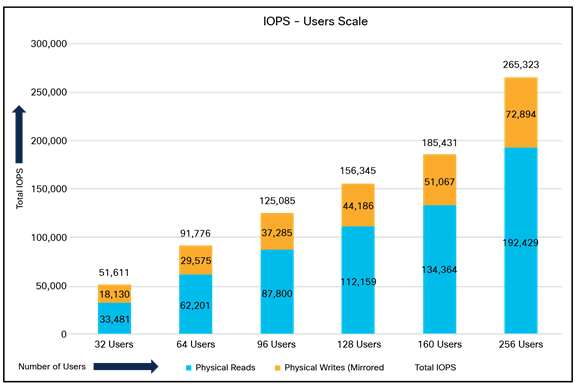
IPOS for CDBDB database for different numbers of users
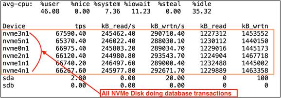
The following screenshot shows how each of the NVMe drives was doing the reads and writes equally for this OLTP workload test:
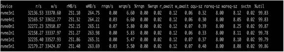
Figure 14 shows the Transactions Per Minute (TPM) and system usage for the same tests in Table 3 on the CDBDB database for running the workload from 32 users to 256 users.
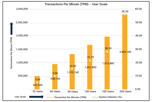
RPM and system usage for tests in Table 3
We also ran the maximum number of users (256) test for a 24-hour period to check the system performance. For the entire 24-hour test, we observed that the system performance (IOPS and throughput) were consistent throughout, and we did not observe any dips in performance while running one OLTP database stress test on this single-instance Oracle Database node.
NVMe device failure protection
The goal of this test is to help ensure that this solution withstands a failure resulting from an unexpected system crash or hardware failure. This section discusses one NVMe SSD failure on a Cisco UCS X210C M6 blade server and the best practices for restoring the system back to normal running condition.
Note: For RHEL 8.3, hot NVMe drive removal and insertion are supported with this release of firmware. Please refer to the support matrix for more details about the supported OS list.
Here, we performed several tests by pulling out or deleting partitions on one of the NVMe SSDs while the system was running a full workload. The main goals were to measure the following:
● Impact of the NVMe SSD failure on system performance when the workload was running.
● Rebalancing time for the Oracle ASM disk group under full database workload scenarios.
● Latency during failure of an NVMe SSD and rebalancing of the ASM disk group while the workload was running.
For this test, we ran the swingbench OLTP database workload. We pulled out one NVMe and inserted a new NVMe SSD while this database workload was running. Table 4 lists the high-level steps to perform failure and restore the system to its normal condition.
Table 4. Steps to perform failure and restore the system
| Steps |
Actions |
Expected behaviour |
| Step 1: Run database workload |
Run the OLTP database workload. |
Normal working condition |
| Step 2: Failure on one NVMe drive |
Remove one NVMe disk by pulling it out from blade server. |
|
| Check the ASM disk group and drop the failed disk from the existing disk group. |
Workload continue to run but with some (minimal) impact on transactions |
|
| Step 3: Insert new NVMe drive |
Insert the new NVMe drive into blade server |
Workload continue to run with minimal impact |
| Step 4: Update UDEV rules, add new disk into disk group, and start rebalance operation |
Find the WWN of the new inserted disk and update the UDEV rules to assign read/write permission for the database user. |
|
| Add the new disk into the ASM disk group and start the disk group rebalance operations. |
Transaction impact will vary depending upon workload read/write characteristics, load, etc. |
|
| Step 5: Database workload back to normal state |
Observe the disk group rebalance operation complete and database performance go back to normal running conditions. |
Workload back to normal working conditions |
Step 1. Run the database workload
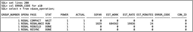
We started the database workload with the maximum number of 256 users and captured IOSTAT to see each NVMe disk I/O operation:
Step 2. Failure on one NVMe drive
While the database was running the workload, one of the NVMe disk sd was pulled out and taken offline from the ASM disk group. After we pulled one disk, we captured IOSTAT (refer to the following screenshot) and observed that the failed disk (nvme0n1) could not perform any I/O operations:
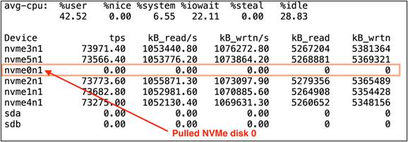
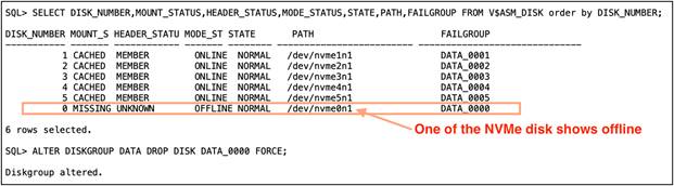
This sudden hot removal of an NVMe SSD also did not cause the database to fail. The database workload continued to run with very minimal performance impact on overall TPS, TPM, IOPS, or latency until we got the new NVMe SSD to replace it. Also, we logged in as a database user and dropped the failed NVMe disk from the ASM data disk group:
Steps 3 and 4: Insert a new NVMe drive, update UDEV rules, add a new disk into the disk group, and start the rebalance operation:
After some time, we inserted a new NVMe drive into the blade server and performed the following steps to add the new disk into the existing database:
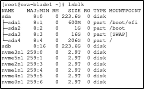
1. Find the new NVMe drive and its wwn id by using the following command:
[root@ora-blade1 ~]# lsblk
NAME MAJ:MIN RM SIZE RO TYPE MOUNTPOINT
sda 8:0 0 223.6G 0 disk
| ├─sda1 |
8:1 |
0 |
600M |
0 |
part |
/boot/efi |
||
| ├─sda2 |
8:2 |
0 |
1G |
0 |
part |
/boot |
||
| ├─sda3 |
8:3 |
0 |
16G |
0 |
part |
[SWAP] |
||
| └─sda4 |
8:4 |
0 |
206G |
0 |
part |
/ |
||
| sdb |
8:16 |
0 |
223.6G |
0 |
disk |
|||
| nvme3n1 |
259:0 |
0 |
2.9T |
0 |
disk |
|||
| nvme5n1 |
259:1 |
0 |
2.9T |
0 |
disk |
|||
| nvme6n1 |
259:2 |
0 |
2.9T |
0 |
disk |
|||
| nvme2n1 |
259:3 |
0 |
2.9T |
0 |
disk |
|||
| nvme1n1 |
259:4 |
0 |
2.9T |
0 |
disk |
|||
| nvme4n1 |
259:5 |
0 |
2.9T |
0 |
disk |
|||
[root@ora-blade1 ~]# /usr/bin/lsblk -o wwn /dev/nvme6n1 WWN
eui.01000000000000005cd2e4bfc6625351
2. Update the UDEV rules file using the new disk id and re-load the UDEV rules services:
[root@ora-blade1 ~]# vi /etc/udev/rules.d/80-nvme.rules [root@ora-blade1 ~]# cat /etc/udev/rules.d/80-nvme.rules
#KERNEL=="nvme[0-9]*n[0-9]*", ENV{DEVTYPE}=="disk", ENV{ID_WWN}=="eui.01000000000000005cd2e4a074385351", SYMLINK+="ASMDISK1", GROUP:="oinstall", OWNER:="oracle", MODE:="660"
KERNEL=="nvme[0-9]*n[0-9]*", ENV{DEVTYPE}=="disk", ENV{ID_WWN}=="eui.01000000000000005cd2e4cb74385351", SYMLINK+="ASMDISK2", GROUP:="oinstall", OWNER:="oracle", MODE:="660"
KERNEL=="nvme[0-9]*n[0-9]*", ENV{DEVTYPE}=="disk", ENV{ID_WWN}=="eui.01000000000000005cd2e4c07c385351", SYMLINK+="ASMDISK3", GROUP:="oinstall", OWNER:="oracle", MODE:="660"
KERNEL=="nvme[0-9]*n[0-9]*", ENV{DEVTYPE}=="disk", ENV{ID_WWN}=="eui.01000000000000005cd2e49a7c385351", SYMLINK+="ASMDISK4", GROUP:="oinstall", OWNER:="oracle", MODE:="660"
KERNEL=="nvme[0-9]*n[0-9]*", ENV{DEVTYPE}=="disk", ENV{ID_WWN}=="eui.01000000000000005cd2e4d37c385351", SYMLINK+="ASMDISK5", GROUP:="oinstall", OWNER:="oracle", MODE:="660"
KERNEL=="nvme[0-9]*n[0-9]*", ENV{DEVTYPE}=="disk", ENV{ID_WWN}=="eui.01000000000000005cd2e4b9db625351", SYMLINK+="ASMDISK6", GROUP:="oinstall", OWNER:="oracle", MODE:="660"
KERNEL=="nvme[0-9]*n[0-9]*", ENV{DEVTYPE}=="disk", ENV{ID_WWN}=="eui.01000000000000005cd2e4bfc6625351", SYMLINK+="ASMDISK7", GROUP:="oinstall", OWNER:="oracle", MODE:="660"
[root@ora-blade1 ~]# udevadm control --reload-rules [root@ora-blade1 ~]# udevadm trigger
3. Confirm the ASM disk and its correct permissions:
[root@ora-blade1 ~]# ls -al /dev/ASM*
| lrwxrwxrwx |
1 |
root |
root |
7 |
Dec |
16 |
22:13 |
/dev/ASMDISK2 |
-> |
nvme1n1 |
| lrwxrwxrwx |
1 |
root |
root |
7 |
Dec |
16 |
22:13 |
/dev/ASMDISK3 |
-> |
nvme2n1 |
| lrwxrwxrwx |
1 |
root |
root |
7 |
Dec |
16 |
22:13 |
/dev/ASMDISK4 |
-> |
nvme3n1 |
| lrwxrwxrwx |
1 |
root |
root |
7 |
Dec |
16 |
22:13 |
/dev/ASMDISK5 |
-> |
nvme4n1 |
| lrwxrwxrwx |
1 |
root |
root |
7 |
Dec |
16 |
22:13 |
/dev/ASMDISK6 |
-> |
nvme5n1 |
| lrwxrwxrwx |
1 |
root |
root |
7 |
Dec |
16 |
22:13 |
/dev/ASMDISK7 |
-> |
nvme6n1 |
4. Log in as a database user and add the new ASM disk to the existing ASM disk group and start the rebalance opertions. For this test, we used power 4 and captured the system statistics:
[root@ora-blade1 ~]# su - grid [grid@ora-blade1 ~]$ sqlplus / as sysasm
SQL*Plus: Release 19.0.0.0.0 - Production on Tue Feb 15 05:04:46 2022
Version 19.10.0.0.0
Copyright (c) 1982, 2019, Oracle. All rights reserved.
Connected to:
Oracle Database 19c Enterprise Edition Release 19.0.0.0.0 - Production Version 19.10.0.0.0
SQL> alter diskgroup data add disk '/dev/ASMDISK7' force;
Diskgroup altered.
SQL> alter diskgroup data rebalance power 4;
Diskgroup altered.
Note: After you configure and add a new NVMe drive to the ASM diskgroup, you have various rebuild power (aggressiveness) options for rebalancing the ASM disk group. The rebuild times typically depend on the database workloads and database schema size.
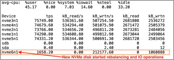
5. Capture the ASM disk group rebalance opertions time and system performance through IOSTAT:
We captured the IOSTAT and found out the new disk started rebalance operations and database transcations:
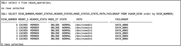
6. Confirm that the ASM disk group and database workload are back to normal working conditions:
From the previous observations, we conclude that during one of the drive failures some database transactions were affected because of drive re-built operations. However, the database continued to run. The effect of database transactions will vary based on the read and write workloads.
Figure 15 represents the summary of all stages and database TPM for this failure test as:
Stage 1: Observed workload running in normal conditions.
Stage 2: Pulled one NVMe drive and dropped failed drive from ASM disk group.
Stage 3: Inserted new NVMe drive, updated UDEV rules, and added new drive to ASM disk group.
Stage 4: Started ASM disk group rebalance operations.
Stage 5: Observed database workload back to normal running condition.
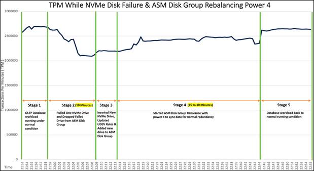
Summary of TPM for failure test
As we observed from Figure 15, when we pulled one of the NVMe drives while the OLTP database workload was running (stage 2), we observed minimal impact on transactions and the system continued to run without any failure. We let the system run with this failed NVMe state for around 10-15 minutes and also noticed no crash or database performance impact overall to the system. We inserted a new NVMe drive (stage 3) and added the new disk to the ASM disk group and started the ASM disk group rebalance operation with power 4 (stage 4) and monitored a significant impact on transactions as operations on the disk group were re-built. After the disk was added into the ASM disk group and rebalance operations were completed, the database workload resumed to peak performace as before.
Also, we didn't run any database workload, and we performed the NVMe SSD failure test by removing one of the NVMe drives. We insterted a new NVMe drive, removed a failed ASM disk from the existing disk group, and added the new disk into the DATA disk group. After adding the drive into the disk group, we started rebalance operations with power 8 and captured the time it took to complete the rebalance operations as well as the overall time to bring the disk group and system back to normal. We observed that it took around 12-15 minutes (depending on database schema of 3 TB) to complete the ASM disk group rebalance operation and synchronize the data across all six drives for normal redunadnacy.
The beating "heart" of innovation, applications are the direct expression of consumer demand and your presence. Applications have forced a whole new way of thinking about IT. The old rules no longer apply. It's not on premises vs. cloud. It's both. It's massive scale and granular control. It's always-on availability enabled by modular components that can be molded and shaped to the needs of your applications. It's a new game where developers are free to write their own rules but where IT must free itself from the burden of managing massive complexity in order to keep up.
Tomorrow will think differently, wanting hardware that thinks like software. The Cisco UCS X-Series with Intersight is a modular system managed from the cloud. It is designed be shaped to meet the needs of modern applications and improve operational efficiency, agility, and scale through an adaptable, future- ready, modular design. The Cisco UCS X-Series Modular System simplifies your data center, adapting to the unpredictable needs of modern applications while also providing for traditional scale-out and enterprise workloads. It reduces the number of server types to maintain, helping improve operational efficiency and agility as it helps reduce complexity. Powered by the Cisco Intersight cloud-operations platform, it shifts users' IT focus from administrative details to business outcomes-with a hybrid-cloud infrastructure that is assembled from the cloud, shaped to their workloads, and continuously optimized.
Consult the following references for additional information about the topics discussed in this document.
Products and solutions
● Cisco UCS X-Series Modular System:
● Oracle Grid Infrastructure and Database 19c configuration
Cisco UCS X9508 Chassis:
Cisco UCS X210c M6 Compute Node:
Cisco Intersight technology:
https://www.cisco.com/c/en/us/products/cloud-systems-management/intersight/index.html.
Cisco UCS 6400 Series Fabric Interconnect:
Configuration guides:
● Cisco UCS X-Series Quick Start Guide:
● Cisco UCS X-Series Modular System with Intersight Solution Overview: https://www.cisco.com/c/en/us/products/collateral/servers-unified-computing/ucs-x-series-modular-system/solution-overview-c22-2432175.html
● Cisco UCS X-Series Performance in a Single Chassis: