Cisco Network Convergence System 1001 OTDR Line Card Data Sheet
Available Languages
Bias-Free Language
The documentation set for this product strives to use bias-free language. For the purposes of this documentation set, bias-free is defined as language that does not imply discrimination based on age, disability, gender, racial identity, ethnic identity, sexual orientation, socioeconomic status, and intersectionality. Exceptions may be present in the documentation due to language that is hardcoded in the user interfaces of the product software, language used based on RFP documentation, or language that is used by a referenced third-party product. Learn more about how Cisco is using Inclusive Language.
NCS 1001 provides unmatched levels of automation and visibility for point-to-point metro optical line systems. Cisco has enhanced this further with the introduction of inline and real-time OTDR-based reporting. The OTDR line card will allow users to scan the fiber at will to profile fiber loss and detect ORL, reflection, and attenuation events.
The Cisco® NCS 1001 OTDR Line Card (Figure 1) occupies one slot in the 1RU NCS 1001 Line System platform. The module provides two bidirectional OTDRs and corresponding filters to combine the OTDR signals with the OSC and C-Band channels.
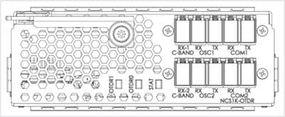
Cisco NCS 1001 OTDR Line Card front view
The Cisco NCS 1001 OTDR Line Card provides the following benefits:
● Bidirectional OTDR up to 100 km. The OTDR operates inline and in real time with no interruption to traffic.
● Embedded filter for combining OTDR with OSC and C-Band channels.
● Multiple deployment models can be supported—terminal, ILA, and standalone.
● Compact one-third of an RU. Up to 6x OTDRs in one RU.
● Auto-mode and expert modes available depending on what the user requires.
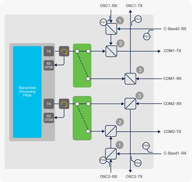
Cisco NCS 1001 functional block diagram
The Cisco NCS 1001 OTDR can be used in the following configurations:
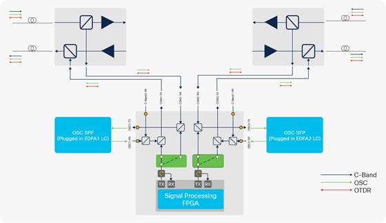
● Terminal node with unprotected or protected amplifiers at the end points of a point-to-point link. Figure 3 illustrates how the OTDR line card connects into a protected terminal node that has two amplifier modules.
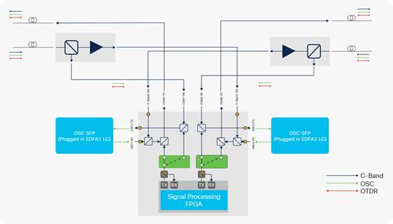
● Inline Amplifier Node with two amplifiers modules—one for each direction. Figure 4 shows how the OTDR line card connects to the two amplifier modules.
● Standalone for use with any third-party line system.
NCS 1001 protected terminal node use case for OTDR
NCS 1001 ILA node use case for OTDR
The Cisco NCS 1001 provides comprehensive management capabilities to support Operations, Administration, Maintenance, and Provisioning (OAM&P) capabilities through IOS-XR CLI, SNMP, Syslog, and XML. For machine-to-machine configuration and management of NCS 1001, NETCONF, RESTCONF, and gRPC transport protocols with JSON, XML, and GPB encoding are provided. OpenConfig protocols for management GNMI and operations GNOI are also supported. The NCS 1001 provides a set of native YANG models as well as the ability to map into any industry standard or customer-defined YANG data models. For monitoring, NCS 1001 provides a streaming telemetry feature that relies on a push mechanism to disseminate user-selected PM and status information at user specified frequencies at granular 10-second intervals. This improves monitoring speed and scale compared to traditional pull-based mechanisms such as SNMP. The telemetry infrastructure also allows for events such as alarms and port-state changes to be notified.
The auto mode allows the user to run a scan measurement without specifying the fiber distance or zone where this measurement has to be performed. The system will automatically tune the granularity of the measurement to provide the best result. The auto mode includes two training phases: ORL training and OTDR training. This training is under system control and occurs without user intervention. Results of the training phases shall be available through show commands.
The expert mode allows the user to have full control over OTDR parameters. The expert mode enables expert users who understand how best to set the configuration parameters, which include reflection sensitivity, loss sensitivity, total loss (dB), capture start point (km), capture end point (km), measurement time (s), pulse width (us), and fiber resolution (m).
The Cisco NCS 1001 supports performance monitoring of optical parameters. Calculation and accumulation of the performance-monitoring data are supported in 30-second, 15-minute, and 24-hour intervals as per G.7710.
After each OTDR scan, ORL measured over the span and fiber end are reported, as well as a list of events. Each event type includes measurement information on loss, reflection, location (km), accuracy (m), and magnitude (dB). The system can save up to 50 events in total and 20 last scans for each slot. Measurement data from OTDR scans can also be exported by the user through an .SOR file. Alarms/SYSLOGs are raised for high ORL, reflection, or Loss after a scan. In case an OTDR scan fails, a SYSLOG message is raised with the corresponding reason for the failure.
The NCS 1001 provides a set of port and system LEDs for a quick visual check of the operational status. The various LEDs are described in detail in Table 4.
The following table summarizes the features of the NCS 1001.
Table 1. Optical specifications
| Item |
Notes |
Value |
Metric |
| OTDR operation bandwidth |
|
1518 nm |
nm |
| OTDR dynamic (maximum supported attenuation: span loss plus concentrated loss) |
Central office |
1.8 |
dB |
| Raman application |
7.3 |
dB |
|
| Regional |
16.3 |
dB |
|
| Long haul |
20.3 |
dB |
|
| Operating range |
Central office |
1 to 1000 |
mt |
| Raman application |
1 to 25 |
km |
|
| Regional |
25 to 80 |
km |
|
| Long haul |
80 to 100 |
Km |
|
| EVENT reporting |
|||
| Distance resolution |
Central office |
1 |
mt |
| Raman application |
2 |
mt |
|
| Regional |
4 |
mt |
|
| Long haul |
5 |
mt |
|
| Attenuation EVENT reporting |
|||
| Attenuation event sensitivity settable (min-max measurement event) |
Central office |
0.5 - 5 |
dB |
| Raman application |
0.6 - 5 |
dB |
|
| Regional |
1.5 - 5 |
dB |
|
| Long haul |
1.5 - 5 |
dB |
|
| Range of attenuation of measurable events (single event) |
Central office |
1 - 1.8 |
dB |
| Raman application |
0.6 - 5 |
dB |
|
| Regional |
1.5 - 5 |
dB |
|
| Long haul |
1.5 - 5 |
dB |
|
| Event loss measurement accuracy |
Central office |
<0.5 |
dB |
| Raman application |
<0.5 |
dB |
|
| Regional |
<0.5 |
dB |
|
| Long haul—assuming total 20-dB loss (span and events) |
<0.5 |
dB |
|
| Reflection EVENT reporting |
|||
| Reflection event sensitivity settable range (min-max measurement event) |
Central office |
-14 to -40 |
dB |
| Raman application |
-14 to -40 |
dB |
|
| Regional |
-14 to -40 |
dB |
|
| Long haul |
-14 to -40 |
dB |
|
| Range of reflection amplitude of measurable events (single event)—high reflection range |
Central office |
-14 to -35 |
dB |
| Raman application |
-14 to -35 |
dB |
|
| Regional |
-14 to -35 |
dB |
|
| Long haul |
-14 to -35 |
dB |
|
| Range of reflection amplitude of measurable events (single event)—low reflection range |
Central office |
-35 to -45 |
dB |
| Raman application |
-35 to -45 |
dB |
|
| Regional |
-35 to -40 |
dB |
|
| Long haul |
-35 to -40 |
dB |
|
| Event reflection measurement accuracy—high reflection range |
Central office |
±2 |
dB |
| Raman application |
±2 |
dB |
|
| Regional |
±3 |
dB |
|
| Long haul |
±5 |
dB |
|
| Event reflection measurement accuracy—low reflection range |
Central office |
±3 |
dB |
| Raman application |
±3 |
dB |
|
| Regional |
±4 |
dB |
|
| Long haul |
±6 |
dB |
|
Table 2. Filter specifications
| Item |
Notes |
Value |
Metric |
| OSC + C-Band (1) |
OSC |
1600 to 1620 |
nm |
| C-Band |
1528 to 1570 |
nm |
|
| OSC + OTDR + C-Band (2) |
OSC |
1600 to 1620 |
nm |
| OTDR |
1500 to 1520 |
nm |
|
| C-Band |
1528 to 1570 |
nm |
|
| OSC + OTDR (3) |
OTDR |
1500 to 1520 |
nm |
| OSC |
1600 to 1620 |
nm |
|
| IL path |
OSC-RX to COM-TX |
1.9 |
dB |
| C-Band to COM-TX |
1.6 |
dB |
|
| COM-RX to OSC-TX |
1.7 |
dB |
|
| In-band insertion loss ripple |
|
0.4 |
dB |
| Isolation |
COM-RX to OSC-TX |
15 |
dB |
Table 3. Dead zone specifications
| Item |
Notes |
-14 |
-16 |
-20 |
-25 |
-30 |
-35 |
-40 |
-45 |
| Reflective dead zone (m) |
Central office—1 km |
8 |
8 |
8 |
8 |
2 |
2 |
2 |
2 |
| Raman application—25 km |
60 |
60 |
60 |
60 |
60 |
60 |
60 |
30 |
|
| Regional—80 km |
550 |
550 |
550 |
550 |
500 |
250 |
220 |
220 |
|
| Long haul—100 km |
3000 |
3000 |
3000 |
2000 |
1000 |
1000 |
1000 |
- |
|
| Attenuation dead zone (m) |
Central office (with long-tail compensation) |
17 |
17 |
15 |
13 |
10 |
9 |
9 |
8 |
| Central office (without long-tail compensation) |
500 |
500 |
500 |
60 |
50 |
40 |
30 |
20 |
|
| Raman application (with long-tail compensation) |
215 |
200 |
185 |
170 |
155 |
140 |
140 |
140 |
|
| Raman application (without long-tail compensation) |
800 |
800 |
500 |
300 |
250 |
250 |
200 |
200 |
|
| Regional |
1400 |
1400 |
1350 |
1350 |
1250 |
550 |
350 |
300 |
|
| Long haul |
4200 |
4200 |
4100 |
3600 |
2200 |
2100 |
1800 |
1600 |
Table 3 lists regulatory compliance information for the trunk card. Note that all compliance documentation may not be completed at the time of product release. Please check with your Cisco sales representative for countries other than Canada, the United States, and the European Union.
|
● EMC (Immunity)
|
● IEC/EN61000-4-2 Electrostatic Discharge Immunity
● IEC/EN61000-4-3 Radiated Immunity
● IEC/EN61000-4-4 EFT-B Immunity
● IEC/EN61000-4-5 Surge AC Port
● IEC/EN61000-4-6 Immunity to Conducted Disturbances
● IEC/EN61000-4-11 Voltage Dips, Short Interruptions, and Voltage Variations
● KN 24
|
|
● EMC (ETSI/EN)
|
● EN 300 386 Telecommunications Network Equipment (EMC)
● EN55022 Information Technology Equipment (Emissions)
● EN55024/CISPR 24 Information Technology Equipment (Immunity)
● EN50082-1/EN61000-6-1 Generic Immunity Standard
● EN61000-3-2 Power Line Harmonics
● EN61000-3-3 Voltage Changes, Fluctuations, and Flicker
|
| Safety |
|
|
● CSA C22.2 #60950-1—Edition 7, March 2007
● UL 60950-1—Edition 2, 2014
|
● IEC 60950-1 Information technology equipment - Safety - Part 1: General requirements - Edition 2 (2005) + Amendment 1 2009 + Amendment 2 2013
● EN 60950-1: Edition 2 (2006) Information technology equipment - Safety - Part 1: General requirements + A11:2009 + A1:2010 + A12:2011 + A2:2013
● CE Safety directive: 2006/95/EC
|
| Laser |
|
|
● 21CFR1040 (2008/04) (Accession Letter and CDRH Report) Guidance for Industry and FDA Staff (Laser Notice No. 50), June 2007
|
● IEC 60825-1: 2007 Edition 2.0 Safety of laser products - Part 1: Equipment classification, requirements, and user guide
● IEC60825-2 Edition 3.2 (2010) Safety of laser products - Part 2: Safety of optical fiber communication systems
|
| Optical |
|
|
● ITU-T G.691
|
● ITU-T G.975
|
Table 4 provides card specifications, Table 5 provides ordering information.
Table 4. NCS 1001 specifications
| Management |
|
| OTDR 0/1 LED
● Activity present
● Alarm present
● No activity
|
Green blinking Yellow Blank |
| Status LEDs
● The unit is operating correctly.
● The unit has one or more errors detected.
● Power is not applied to the unit.
|
Green Yellow Off |
| Power |
|
|
● Maximum
|
40 W |
| Physical |
|
| Dimensions |
4.2” wide x 9.4” deep x 1.5” tall |
| Weight |
0.5 Kg |
| Storage temperature |
-28°C to 70°C (-20°F to 158°F) |
| Operating temperature
● Normal
|
0°C to 40°C (32°F to 104°F) |
| Relative humidity
● Normal
● Short-term
1
|
5% to 85%, noncondensing 5% to 90%, but not to exceed 0.024 kg water/kg of dry air |
| 1 Short-term refers to a period of not more than 96 consecutive hours and a total of not more than 15 days in 1 year (a total of 360 hours in any given year, but no more than 15 occurrences during that 1-year period). |
|
Table 5. Ordering information
| Part Number |
Description |
| NCS1K-OTDR= |
NCS 1000 Optical Time Domain Reflectometer module |
Flexible payment solutions to help you achieve your objectives
Cisco Capital makes it easier to get the right technology to achieve your objectives, enable business transformation and help you stay competitive. We can help you reduce the total cost of ownership, conserve capital, and accelerate growth. In more than 100 countries, our flexible payment solutions can help you acquire hardware, software, services and complementary third-party equipment in easy, predictable payments. Learn more.