Deploy the Cisco HyperFlex Datacenter without Fabric Interconnect Solution
Available Languages
Bias-Free Language
The documentation set for this product strives to use bias-free language. For the purposes of this documentation set, bias-free is defined as language that does not imply discrimination based on age, disability, gender, racial identity, ethnic identity, sexual orientation, socioeconomic status, and intersectionality. Exceptions may be present in the documentation due to language that is hardcoded in the user interfaces of the product software, language used based on RFP documentation, or language that is used by a referenced third-party product. Learn more about how Cisco is using Inclusive Language.
Cisco HyperFlex™ systems have established themselves as a premier hyperconverged hardware platform for computing virtualization in companies of all sizes. Cisco HyperFlex systems are based on Cisco Unified Computing System™ (Cisco UCS®) hardware, combining Cisco HyperFlex HX-Series x86 rack-mount servers, industry-leading virtualization hypervisor software from VMware, and next-generation software-defined storage (SDS) technology. This combination creates a complete virtualization platform, which provides the network connectivity for the guest virtual machine connections and the distributed storage for housing the virtual machines spread across all the Cisco UCS x86 servers, eliminating the need to use specialized storage or networking components. The unique storage features of the Cisco HyperFlex log-based file system enable rapid cloning of virtual machines, snapshots without the traditional performance penalties, inline data deduplication and compression, and virtual machine protection through replication.
Originally, the Cisco HyperFlex system was offered as a traditional Cisco UCS deployment model, using Cisco UCS fabric interconnects connected to and managing the HX-Series servers. Although this deployment model offers several unique benefits, including cable aggregation, bandwidth combination, unified deployment, and simplified management, it is not the best solution for small-footprint or remote-location deployments, which would not take full advantage of the improvements gained by using the fabric interconnects. Cisco HyperFlex Edge was developed to support limited-size deployments of clusters of up to 4 nodes without the use of the fabric interconnects. This solution is well suited for small locations, branch offices, remote offices, and limited-footprint sites. Deployment of clusters without the use of the Cisco UCS fabric interconnect has now been extended to clusters of up to 12 nodes using an expanded range of Cisco HX-Series servers known as the Cisco HyperFlex Datacenter without Fabric Interconnect (DC-No-FI) solution. This new deployment option supports larger-capacity and higher-performance clusters. It is suitable for true data center workloads at a lower cost, because organizations don’t need to purchase a pair of fabric interconnects and can use the network equipment already deployed.
The Cisco HyperFlex DC-No-FI solution can be configured, deployed, managed, and monitored with standard tools for Cisco UCS and VMware vSphere, such as the cloud-based Cisco Intersight™ management platform, the integrated Cisco HyperFlex Connect HTML management tool, and traditional tools such as VMware vCenter. This powerful linking of advanced technology stacks into a single, simple, rapidly deployed solution makes the Cisco HyperFlex system a true second-generation hyperconverged platform.
This section is organized into the following subsections:
● Audience
Audience
The intended audience for this document includes sales engineers, field consultants, professional services, IT managers, partner engineering staff, and customers deploying the Cisco HyperFlex system. External references are provided wherever applicable, but readers are expected to be familiar with VMware technologies, Cisco Application Specific Infrastructure (Cisco ACI®), infrastructure concepts, network switching and connectivity, and the security policies of the customer installation.
This document describes the best practices and recommendations when deploying Cisco HyperFlex Datacenter without Fabric Interconnect, or DC-No-FI, systems using the VMware ESXi hypervisor through the Cisco Intersight cloud-based management portal. The document is based on all known best practices using the software, hardware, and firmware revisions specified in the document at the time of publication. Therefore, recommendations and best practices may be amended for later versions. This limited-scope document does not fully detail the installation process of a Cisco HyperFlex DC-No-FI cluster, because the process is practically identical to the process of installing a Cisco HyperFlex Edge cluster, which is detailed in its own full Cisco Validated Design document. This document describes the current product requirements and limitations and relevant considerations when deploying a Cisco HyperFlex cluster without using Cisco UCS fabric interconnects. Although readers of this document are expected to have sufficient knowledge to install and configure the products used, configuration details that are important to the deployment of this solution are provided in this document.
● Cisco HyperFlex deployments of 3 to 12 nodes without the use of Cisco UCS fabric interconnects are supported.
● Cisco HyperFlex DC-No-FI is supported on Intel and AMD processor-based Cisco HyperFlex HX220c, HX225c, HX240c, and HX245c model servers.
● All server configurations are allowed, including hybrid, all flash, all flash with Non-Volatile Memory Express (NVMe) cache, and all NVMe.
● Cisco HyperFlex DC-No-FI clusters allow compute-only nodes in up to a 2:1 ratio, depending on licensing.
● Cisco HyperFlex DC-No-FI clusters are supported as a target for Cisco HyperFlex N:1 replication.
● Expansion of an existing Cisco HyperFlex Edge cluster beyond 4 nodes converts the cluster to Cisco HyperFlex DC-No-FI.
Solution summary
The Cisco HyperFlex System provides an all-purpose virtualized server platform, with hypervisor hosts, networking connectivity, and virtual server storage across a set of HX-Series x86 rack-mount servers. Data center architectures have evolved away from the traditional platforms, which typically contained a disparate set of technologies, such as individual servers for applications or hosting virtual machines, network switches connecting endpoints and transferring Ethernet network traffic, and Fibre Channel storage arrays providing block-based storage through a dedicated SAN. The rapid increase in processing power and storage resources available in modern servers has led to the rise of software-defined storage, or SDS, in which distributed software replaces the functions of traditional storage controllers. Using a distributed SDS platform, a group of rack-mount servers can effectively be turned into a clustered storage system. However, if the servers that provide the SDS environment are in fact the same model of server that typically hosts guest virtual machines, why not simply have the servers perform both tasks and collapse the two functions into one? This ultimate combination of resources is what is now known as a hyperconverged infrastructure (HCI). HCI combines the computing, memory, hypervisor, and storage devices of servers into a single platform for virtual servers. There is no longer a separate storage system, because the servers running the hypervisors to host virtual machines also provide the SDS resources to store the virtual servers, ultimately storing the virtual machines on themselves.
The Cisco HyperFlex system is a next-generation hyperconverged platform that uniquely combines the converged computing and networking provided by Cisco UCS with advanced custom hyperconverged storage software to provide the computing resources, network connectivity, distributed storage, and hypervisor platform for running an entire virtualized environment—containing everything in a single uniform system.
Some important advantages of HCI are the simplified deployment and day-to-day management operations and increased agility, thereby reducing ongoing operational costs. Hyperconverged storage also can easily be managed by an IT generalist, eliminating the need for dedicated management teams and specialized skillsets, further reducing costs.
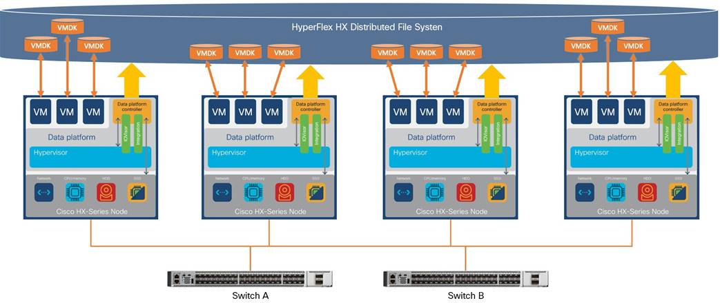
Cisco HyperFlex systems are available in four main configurations: a single-site cluster managed by Cisco UCS fabric interconnects; a split two-site cluster managed by two pairs of Cisco UCS fabric interconnects; a smaller-scale single-site deployment that does not use fabric interconnects, called Cisco HyperFlex Edge; and now Cisco HyperFlex DC-No-FI (Figure 1), which is the subject of this document.
Cisco HyperFlex DC-No-FI overview
Cisco HyperFlex DC-No-FI systems are designed to provide a lower-cost, high-performance, limited-scale cluster for data center workloads. For example, whereas a standard Cisco HyperFlex cluster with fabric interconnects can scale to as many as 32 nodes, DC-No-FI clusters are limited to 12 nodes. Network options are available for 10, 25, 40, and 100 Gigabit Ethernet connection speeds, depending on the hardware chosen, connecting only to a redundant pair of standard Ethernet switches. All current models of Intel and AMD processor–based HX-Series servers can be used, except for the short-depth and large-form-factor models, in all configurations, including hybrid, all-flash, and all-NVMe deployments. Cisco HyperFlex DC-No-FI systems are deployed and managed through the Cisco Intersight cloud-based management platform for Cisco UCS.
The following are the components of a Cisco HyperFlex Edge system using the VMware ESXi hypervisor:
● 3 to 12 Cisco HyperFlex HX-Series rack servers
◦ Cisco HyperFlex HX220c M5S rack server
◦ Cisco HyperFlex HX240c M5SX rack server
◦ Cisco HyperFlex HXAF220c M5S All-Flash rack server
◦ Cisco HyperFlex HXAF240c M5SX All-Flash rack server
◦ Cisco HyperFlex HXAF220c M5SN All-NVMe rack server
◦ Cisco HyperFlex HX220c M6S rack server
◦ Cisco HyperFlex HX225c M6S rack server
◦ Cisco HyperFlex HX240c M6SX rack server
◦ Cisco HyperFlex HX245c M6SX rack server
◦ Cisco HyperFlex HXAF220c M6S All-Flash rack server
◦ Cisco HyperFlex HXAF225c M6S All-Flash rack server
◦ Cisco HyperFlex HXAF240c M6SX All-Flash rack server
◦ Cisco HyperFlex HXAF245c M6SX All-Flash rack server
◦ Cisco HyperFlex HXAF220c M6SN All-NVMe rack server
◦ Cisco HyperFlex HXAF240c M6SN All-NVMe rack server
● Cisco HyperFlex HX Data Platform software
● VMware vSphere ESXi hypervisor
● VMware vCenter Server (end-user supplied)
This section is organized into the following subsections:
● Cisco HyperFlex HX Data Platform Software
● Cisco HyperFlex HX Data Platform Controller
● Data operations and distribution
● All-NVMe and all-flash versus hybrid nodes
● Cisco Intersight cloud-based management
● Cisco HyperFlex Connect HTML 5 management webpage
Cisco HyperFlex HX Data Platform software
The Cisco HyperFlex HX Data Platform is a purpose-built, high-performance, distributed file system with a wide array of enterprise-class data management services. The data platform’s innovations redefine distributed storage technology, exceeding the boundaries of first-generation hyperconverged infrastructures. The data platform has all the features expected in an enterprise shared storage system, eliminating the need to configure and maintain complex Fibre Channel storage networks and devices. The platform simplifies operations and helps ensure data availability. Enterprise-class storage features include the following:
● Data protection creates multiple copies of the data across the cluster so that data availability is not affected if single or multiple components fail (depending on the replication factor configured).
● Deduplication is always on, helping reduce storage requirements in virtualization clusters in which multiple operating system instances in guest virtual machines result in large amounts of replicated data.
● Compression further reduces storage requirements, reducing costs, and the log-structured file system is designed to store variable-sized blocks, reducing internal fragmentation.
● Replication copies virtual machine–level snapshots from one Cisco HyperFlex cluster to another to facilitate recovery from a cluster or site failure through failover to the secondary site of all the virtual machines.
● Thin provisioning allows large volumes to be created without requiring storage to support them until the need arises, simplifying data volume growth and making storage a "pay as you grow" proposition.
● Fast, space-efficient clones rapidly duplicate virtual storage volumes so that virtual machines can be cloned simply through metadata operations, with actual data copied only for write operations.
● Snapshots help facilitate backup and remote-replication operations, which are needed in enterprises that require always-on data availability.
● Small Computer System Interface over IP (iSCSI) connectivity allows external systems to consume HX Data Platform storage by presenting volumes to be mounted by the external systems using the iSCSI protocol.
Cisco HyperFlex HX Data Platform controller
A Cisco HyperFlex HX Data Platform controller resides on each node and implements the distributed file system. The controller runs as software in user space within a virtual machine and intercepts and handles all I/O from the guest virtual machines. The storage controller virtual machine (SCVM) uses the VMDirectPath I/O feature to provide direct PCI passthrough control of the physical server’s SAS disk controller or direct control of the PCI-attached NVMe-based solid-state disks (SSDs). This method gives the controller virtual machine full control of the physical disk resources, using the SSD drives as a read-write caching layer and using the hard-disk drives (HDDs) or SSDs as a capacity layer for distributed storage.
The controller integrates the data platform into the VMware vSphere cluster through the use of three preinstalled VMware ESXi vSphere Installation Bundles (VIBs) on each node:
● scvmclient: This VIB, also called the Cisco HyperFlex IO Visor, provides a network file system (NFS) mount point so that the ESXi hypervisor can access the virtual disks that are attached to individual virtual machines. From the hypervisor’s perspective, it is simply attached to a network file system. The IO Visor intercepts guest virtual machine I/O traffic and intelligently redirects it to the Cisco HyperFlex SCVMs.
● STFSNasPlugin: The VMware API for Array Integration (VAAI) storage offload API allows vSphere to request advanced file system operations such as snapshots and cloning. The controller implements these operations through manipulation of the file system metadata rather than actual data copying, providing rapid response, and thus rapid deployment of new environments.
● stHypervisorSvc: This VIB adds enhancements and features needed for Cisco HyperFlex data protection and virtual machine replication.
Data operations and distribution
The Cisco HyperFlex HX Data Platform controllers handle all read and write operation requests from the guest virtual machines to their virtual disks (VMDKs) stored in the distributed data stores in the cluster. The data platform distributes the data across multiple nodes of the cluster, and also across multiple capacity disks for each node, according to the replication-level policy selected during the cluster setup. This method avoids storage hotspots on specific nodes, and on specific disks of the nodes, and thereby also avoids networking hotspots, or congestion caused by accessing more data on some nodes than others.
The policy for the number of duplicate copies of each storage block is chosen during cluster setup and is referred to as the replication factor (RF).
● Replication factor 3: For every I/O write committed to the storage layer, two additional copies of the blocks written will be created and stored in separate locations, for a total of three copies of the blocks. Blocks are distributed in such a way as to ensure that multiple copies of the blocks are not stored on the same disks, nor on the same nodes of the cluster. This setting can tolerate simultaneous failures of two entire nodes in a cluster of five nodes or more without losing data or requiring restore-from-backup or other recovery processes. RF=3 is recommended for all production systems and is the default for all clusters of three nodes or more.
● Replication factor 2: For every I/O write committed to the storage layer, one additional copy of the blocks written will be created and stored in separate locations, for a total of two copies of the blocks. Blocks are distributed in such a way as to ensure that multiple copies of the blocks are not stored on the same disks, nor on the same nodes of the cluster. This setting can tolerate a failure of one entire node without losing data or requiring restore-from-backup or other recovery processes. RF=2 is suitable for nonproduction systems and for environments for which the extra data protection is not needed.
Data write and compression operations
Internally, the contents of each guest virtual machine's virtual disks are subdivided and spread across multiple servers by the HX Data Platform software. For each write operation, the data is intercepted by the IO Visor module on the node on which the virtual machine is running, a primary node is determined for that particular operation through a hashing algorithm, and then the data is sent to the primary node through the network. The primary node compresses the data in real time and writes the compressed data to the write log on its caching SSD. Then replica copies of that compressed data are sent through the network and written to the write log on the caching SSD of the remote nodes in the cluster, according to the replication factor setting.
For example, at RF=3, a write operation will be written to the write log of the primary node for that virtual disk address, and two additional write operations will be committed in parallel on two other nodes. Because the virtual disk contents have been divided and spread out by the hashing algorithm for each unique operation, this method results in all write operations being spread across all nodes, avoiding problems with data locality and with "noisy" virtual machines consuming all the I/O capacity of a single node. The write operation will not be acknowledged until all three copies are written to the caching layer SSDs. Written data is also cached in a write log area resident in memory in the controller virtual machine, along with the write log on the caching SSDs. This process speeds up read requests when read operations are requested for data that has recently been written.
Data destaging and deduplication
The Cisco HyperFlex HX Data Platform constructs multiple write log caching segments on the caching SSDs of each node in the distributed cluster. As write cache segments become full, and based on policies accounting for I/O load and access patterns, those write cache segments are locked, and new write operations roll over to a new write cache segment. The data in the now-locked cache segment is then deduplicated and destaged to the capacity layer of the nodes for long-term storage. On hybrid systems, the now-deduplicated and compressed data is also written to the dedicated read cache area of the caching SSD, which speeds up read requests for data that has recently been written. When the data is destaged to the capacity disks, it is written in a single sequential operation, avoiding disk-head seek thrashing on the spinning disks and accomplishing the task in the least amount of time. Because the data is already deduplicated and compressed before it is written, the platform avoids the additional I/O overhead often experienced on competing systems, which must then later perform a read, deduplication, compress, and write cycle.
Figure 2 shows this data movement.
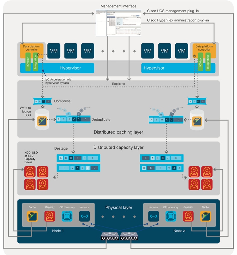
Cisco HyperFlex HX Data Platform data movement
For data read operations, data may be read from multiple locations. For data that was very recently written, the data is likely to still exist in the write log of the local platform controller memory or in the write log of the local caching layer disk. If local write logs do not contain the data, the distributed file system metadata will be queried to see if the data is cached elsewhere, either in write logs of remote nodes or in the dedicated read cache area of the local and remote caching SSDs of hybrid nodes. Finally, if the data has not been accessed in a significant amount of time, the file system will retrieve the requested data from the distributed capacity layer. As requests for read operations are made to the distributed file system and the data is retrieved from the capacity layer, the caching SSDs of hybrid nodes populate their dedicated read cache area to speed up subsequent requests for the same data. This multitiered distributed system with several layers of caching techniques helps ensure that data is served at the highest possible speed, using the caching SSDs of the nodes fully and equally. All-flash configurations do not employ a dedicated read cache; such caching would not provide any performance benefit because the persistent data copy already resides on high-performance SSDs.
In summary, the Cisco HyperFlex HX Data Platform implements a distributed, log-structured file system that performs data operations through two configurations:
● In a hybrid configuration, the data platform provides a caching layer using SSDs to accelerate read requests and write responses, and it implements a storage capacity layer using HDDs.
● In an all-flash or all-NVMe configuration, the data platform provides a dedicated caching layer using high-endurance SSDs to accelerate write responses, and it implements a storage capacity layer also using SSDs. Read requests are fulfilled directly from the capacity SSDs, because a dedicated read cache is not needed to accelerate read operations.
All-NVMe and all-flash versus hybrid nodes
Cisco HyperFlex systems can be divided logically into two families: a collection of hybrid nodes, and a collection of all-flash or all-NVMe nodes.
Hybrid nodes use a combination of SSDs for the short-term storage caching layer and HDDs for the long-term storage capacity layer. The hybrid Cisco HyperFlex system is an excellent choice for entry-level or midrange storage solutions, and hybrid solutions have been successfully deployed in many nonperformance-sensitive virtual environments.
However, the number highly performance-sensitive and mission-critical applications being deployed is increasing rapidly. The primary challenge to hybrid Cisco HyperFlex systems for these performance-sensitive applications is their increased sensitivity to storage latency. Due to the characteristics of the spinning hard disks, which results in higher latency, HDDs almost inevitably become a bottleneck in a hybrid system. Ideally, if all the storage operations occurred on the caching SSD layer, the hybrid system’s performance would be excellent. But in some scenarios, the amount of data being written and read exceeds the caching layer capacity, placing larger loads on the HDD capacity layer, and the subsequent increase in latency results in reduced performance.
Cisco HyperFlex all-flash and all-NVMe systems are an excellent option for customers with high-performance, latency-sensitive workloads. Because the capacity layer disks are also SSDs, the all-flash and all-NVMe systems avoid the increased latency seen in hybrid nodes when large amounts of data are written and read. With a purpose-built, flash-optimized, high-performance log-based file system, the Cisco HyperFlex all-flash and all-NVMe systems provide these features:
● Predictable high performance across all the virtual machines the cluster
● Highly consistent and low latency, which benefits data-intensive applications
● Architecture that can continue to meet your needs in the future; it is well suited for flash-memory configuration, reducing write amplification and flash cell wear
● Cloud-scale solution with easy scale-out and distributed infrastructure and the flexibility to scale out independent resources separately
Cisco HyperFlex support for hybrid, all-flash, and all-NVMe models allows customers to choose the right platform configuration based on their capacity, applications, performance, and budget requirements. All-flash configurations offer repeatable and sustainable high performance, especially for scenarios with a larger working set of data—that is, a large amount of data in motion. All-NVMe configurations elevate performance to an even higher level, with lower latencies for the most demanding applications. Hybrid configurations are a good option for customers who want the simplicity of the Cisco HyperFlex solution, but whose needs are focused on capacity-sensitive solutions, lower budgets, and few performance-sensitive applications.
Cisco Intersight cloud-based management
The Cisco Intersight platform (https://intersight.com) is Cisco’s latest visionary cloud-based management tool (Figure 3). It is designed to provide centralized off-site management, monitoring, and reporting capabilities for all your Cisco UCS solutions, and it can be used to deploy and manage Cisco HyperFlex clusters. The Cisco Intersight platform offers direct links to Cisco UCS Manager and Cisco HyperFlex Connect for the systems it is managing and monitoring. The Cisco Intersight website and framework is being constantly upgraded and extended with new and enhanced features independently of the products that are managed, meaning that many new features and capabilities can be added with no downtime or upgrades required by the end users. This unique combination of embedded and online technologies results in a complete cloud-based management solution that can care for your Cisco HyperFlex systems throughout the entire lifecycle, from deployment through retirement.
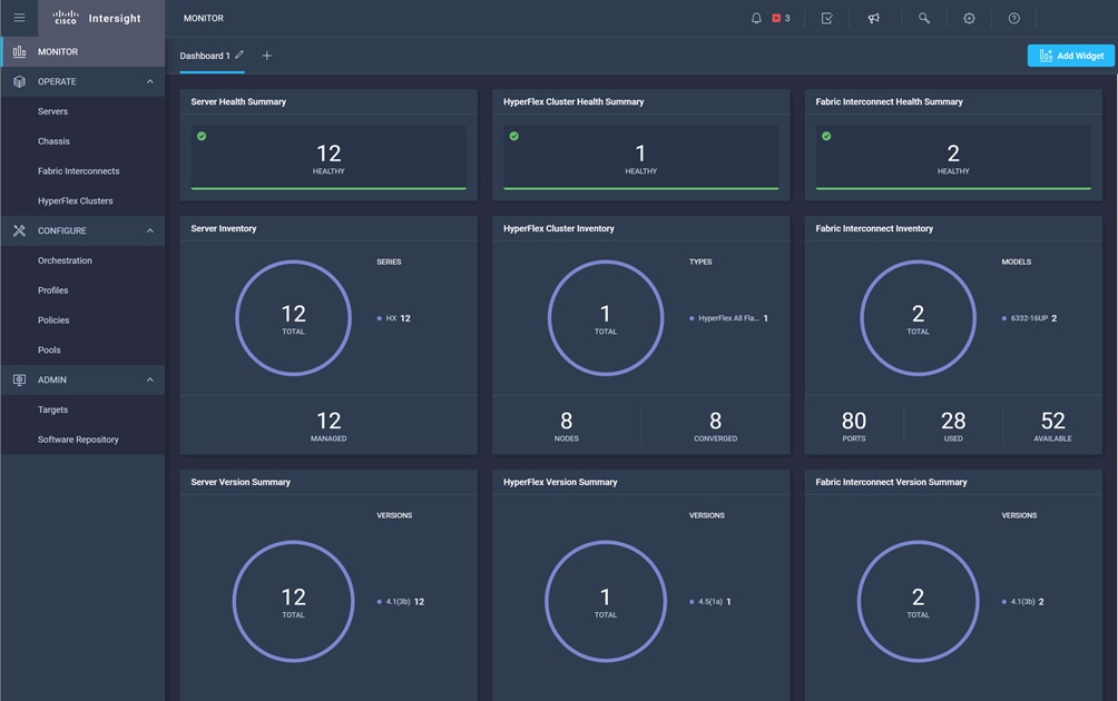
Cisco Intersight platform
Cisco HyperFlex Connect HTML 5 management webpage
An HTML 5–based web user interface named Cisco HyperFlex Connect is available for use as the primary management tool for Cisco HyperFlex systems (Figure 4). Through this centralized point of control for the cluster, administrators can create data stores, monitor the data platform health and performance, manage resource use, and perform upgrades. Administrators can also use this management portal to predict when the cluster will need to be scaled, create virtual machine snapshot schedules, and configure native virtual machine replication. To use the Cisco HyperFlex Connect user interface, connect using a web browser to the Cisco HyperFlex cluster IP address: http://<hx controller cluster ip>.
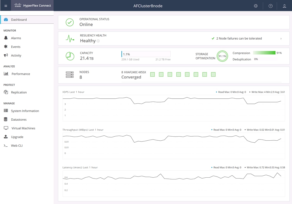
Cisco HyperFlex Connect GUI
This section is organized into the following subsections:
This section discusses the components required for the solution and the physical and logical topologies.
Table 1 lists the required hardware for the Cisco HyperFlex DC-No-FI solution.
| Component |
Hardware |
| Servers |
At least 3, and no more than 12, Cisco HyperFlex HX-Series rack-mount servers. Choose from these models:
● Cisco HyperFlex HX220c M5S
● Cisco HyperFlex HX240c M5SX
● Cisco HyperFlex HXAF220c M5S
● Cisco HyperFlex HXAF240c M5SX
● Cisco HyperFlex HXAF220c M5SN
● Cisco HyperFlex HX220c M6S
● Cisco HyperFlex HX225c M6S
● Cisco HyperFlex HX240c M6SX
● Cisco HyperFlex HX245c M6SX
● Cisco HyperFlex HXAF220c M6S
● Cisco HyperFlex HXAF225c M6S
● Cisco HyperFlex HXAF240c M6SX
● Cisco HyperFlex HXAF245c M6SX
● Cisco HyperFlex HXAF220c M6SN
● Cisco HyperFlex HXAF240c M6SN
|
Table 2 lists the software components and the versions required for a single Cisco HyperFlex DC-No-FI cluster as tested and validated in this document.
| Software |
Version |
| Cisco HyperFlex system |
Cisco HyperFlex HX Data Platform Release 5.0(2a) or later |
| Cisco HyperFlex HX-Series firmware |
M5: Cisco Integrated Management Controller (IMC) firmware Release 4.1(3f) or later M6: Cisco IMC firmware Release 4.2(1e) or later If necessary, upgrade using the Cisco Host Upgrade Utility (HUU), which can be downloaded here: https://software.cisco.com/download/home |
| Hypervisor software |
VMware ESXi 7.0 Update 2 |
| Management server software |
VMware vCenter Server 7.0 Update 2 or Update 3 |
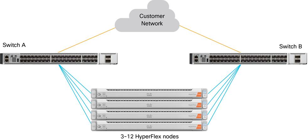
Cisco HyperFlex DC-No-FI physical overview
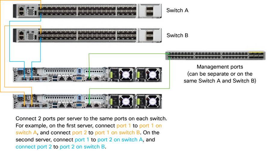
Physical cabling example
Logical topology
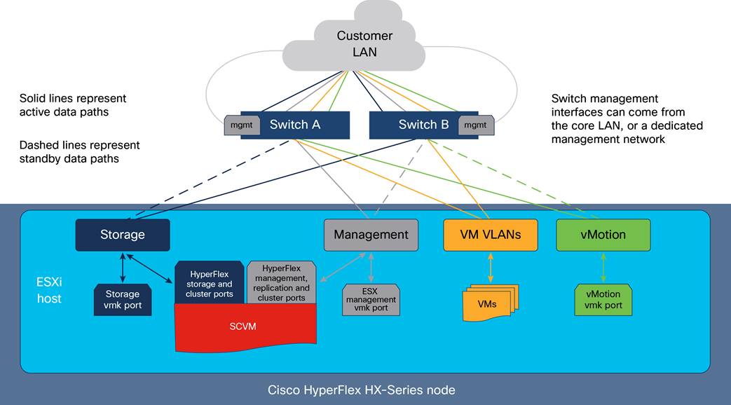
The Cisco HyperFlex system has communication pathways that fall into four defined zones (Figure 7):
● Management zone: This zone comprises the connections needed to manage the physical hardware, the hypervisor hosts, and the SCVMs. These interfaces and IP addresses need to be available to all staff who will administer the Cisco HyperFlex system throughout the LAN and WAN. This zone must provide access to Domain Name System (DNS) and Network Time Protocol (NTP) services, and it must allow Secure Shell (SSH) communication. In addition, for management using the Cisco Intersight platform, these addresses must have access to the internet either directly or through a proxy server. This zone contains multiple physical and virtual components:
◦ Cisco IMC interfaces used by the servers
◦ ESXi host management interfaces
◦ SCVM management interfaces
◦ A roaming Cisco HyperFlex cluster management interface
◦ SCVM replication interfaces
◦ A roaming Cisco HyperFlex cluster replication interface
◦ Network switch management interfaces
● Virtual machine zone: This zone comprises the connections needed to service network I/O to the guest virtual machines that will run inside the Cisco HyperFlex hyperconverged system. This zone typically contains multiple VLANs, which are trunked to the servers through the network uplinks and tagged with IEEE 802.1Q VLAN IDs. These interfaces and IP addresses need to be available to all staff and other computer endpoints that need to communicate with the guest virtual machines in the Cisco HyperFlex system throughout the LAN and WAN.
● Storage zone: This zone comprises the connections used by the Cisco HyperFlex HX Data Platform software, ESXi hosts, and the SCVMs to service the Cisco HyperFlex distributed data file system. These interfaces must be able to communicate with each other at all times for proper operation. During normal operation, this traffic all traverses just one upstream switch. However, in some hardware failure scenarios this traffic would need to move from one switch to another. For this reason, the VLAN used for Cisco HyperFlex storage traffic must be able to traverse the network to reach switch A from switch B, and the reverse. This VLAN does not need to be routable to any other parts of the LAN. This zone contains multiple components:
◦ A VMkernel interface used for storage traffic on each ESXi host in the Cisco HyperFlex cluster
◦ SCVM storage interfaces
◦ A roaming Cisco HyperFlex cluster storage interface
For the best performance, the interfaces in this zone should be configured with jumbo frames, and optionally, they should also use QoS to prioritize storage traffic during times of congestion.
● vMotion zone: This zone comprises the connections used by the ESXi hosts to enable VMware vMotion movement of guest virtual machines from host to host. During normal operation, this traffic all traverses just one upstream switch. However, in some hardware failure scenarios this traffic would need to move from one switch to another. For that reason, the VLAN used for vMotion must be able to traverse the network to reach switch A from switch B, and the reverse.
Logical network design
Note the details listed in this section when setting up your Cisco HyperFlex system.
Cisco HyperFlex systems must be properly licensed using Cisco Smart Licensing, which is a cloud-based software licensing management solution used to automate many manual, time-consuming, and error-prone licensing tasks. The Cisco HyperFlex system communicates with the Cisco Smart Software Manager (SSM) online service through a Cisco Smart Account to check out or assign available licenses from the account to the Cisco HyperFlex cluster resources. Communications can be direct through the internet. You can also configure communication using a proxy server, or through an internal Cisco SSM satellite server, which caches and periodically synchronizes licensing data.
In a small number of highly secure environments, systems can be provisioned with a permanent license reservation (PLR), which does not need to communicate with Cisco SSM. Contact your Cisco sales representative or partner to discuss whether your security requirements will necessitate use of these permanent licenses.
New Cisco HyperFlex cluster installations will operate for 90 days without licensing to provide an evaluation period. Thereafter, the system will generate alarms and operate in a noncompliant mode. Systems without compliant licensing will not be entitled to technical support.
For more information about the Cisco Smart Software Manager satellite server, visit this website: https://www.cisco.com/c/en/us/buy/smart-accounts/software-manager-satellite.html.
Licensing of the Cisco HyperFlex DC-No-FI system requires one license per node from one of two license editions: Cisco HyperFlex Datacenter Advantage or Datacenter Premier. The type of cluster being installed and the features you want to activate and use in the system determine the licenses you need to purchase and the appropriate licensing tier.
Additional features in the future will be added to the different licensing editions as they are released. The features listed in Table 3 are current as of the publication of this document.
Table 3. Cisco HyperFlex system license editions
| Cisco HyperFlex license edition |
Cisco HyperFlex Datacenter Advantage |
Cisco HyperFlex Datacenter Premier |
| Features |
● Cisco HyperFlex DC-No-FI installation on all supported models other than all-NVMe nodes
● 1:1 ratio of compute-only nodes to converged nodes
|
● Everything in the Advantage license plus:
● Cisco HyperFlex DC-No-FI installation on all-NVMe nodes
● 2:1 ratio of compute-only nodes to converged nodes
● Software encryption
|
For a comprehensive guide to licensing and all the features in each edition, consult the Cisco HyperFlex Licensing Guide here: https://www.cisco.com/c/en/us/td/docs/hyperconverged_systems/HyperFlex_HX_DataPlatformSoftware/HX-Ordering-and-Licensing-Guide/b_Cisco_HyperFlex_Systems_Ordering_and_Licensing_Guide.html.
Network connection speed
Cisco HyperFlex HX-Series servers can be ordered with a variety of network interface cards (NICs) installed in the server. For the M6 generation of servers, Cisco requires one of either Cisco UCS VIC 1467 or 1477 to be included. The VIC 1467 is a quad-port 10 and 25 Gigabit Ethernet card, and the VIC 1477 is a dual-port 40 and 100 Gigabit Ethernet card. Cisco recommends that, whenever possible, Cisco HyperFlex DC-No-FI systems should use 25 Gigabit Ethernet speeds or higher for the best performance.
Feature availability
Cisco HyperFlex DC-No-FI clusters support additional features beyond those found in Cisco HyperFlex Edge. However, DC-No-FI clusters support only a subset of the features available in a standard fabric interconnect–managed cluster. Features and deployment options not available in a DC-No-FI deployment include these:
● No support for Microsoft Hyper-V as the hypervisor
● No support for stretched clusters
● No support for self-encrypting drives (SEDs)
● No support for Intel Persistent Memory
● No support for the Cisco HyperFlex acceleration engine
● No support for additional Cisco VICs beyond the single modular LAN-on-motherboard (mLOM) adapter
● No support for the Cisco Intersight Workload Engine
This section is organized into the following subsections:
Installation of the Cisco HyperFlex DC-No-FI cluster is nearly identical to the installation process for a Cisco HyperFlex Edge cluster, using the dual-switch topology. Therefore, detailed steps for the installation process are not presented in this document. Instead, this document discusses only the settings and recommendations that are unique to the DC-No-FI installation. For details and step-by-step instructions for the installation process for Cisco HyperFlex Edge, refer to the following document: https://www.cisco.com/c/en/us/td/docs/unified_computing/ucs/UCS_CVDs/hx_edge_4_5_aci_terraform.html.
Before beginning the installation process, complete the steps described in this section.
Claim devices in the Cisco Intersight platform
The IMC interfaces for all the servers for the new cluster must be configured and online and claimed in the Cisco Intersight platform before you begin the Cisco HyperFlex installation process. Refer to the Cisco Validated Design document for Cisco HyperFlex Edge referenced at the beginning of this section for detailed instructions.
Verify Cisco HyperFlex HX-Series server connectivity
Before you proceed with the Cisco HyperFlex installation, verify that the HX-Series rack servers have active physical links to the upstream switches. Cisco M6 generation HX-Series servers for Cisco HyperFlex systems typically contain the Cisco UCS VIC 1467, which is a 10 or 25 Gigabit Ethernet host adapter. The choice of 10 or 25 Gigabit Ethernet in many cases depends on the switch model to which the nodes will be connected.
Many switch models have ports that are capable of 10 or 25 Gigabit Ethernet; therefore, the determining factor for the resulting interface speed will be the model of interconnect cable and transceiver used. Cables designed for 10 and 25 Gigabit Ethernet use different signaling and different types of forwarding error correction (FEC). In many cases, the interfaces should properly autonegotiate, but in some situations, particularly with 25 Gigabit Ethernet transceivers, the FEC settings on the upstream switches or the Cisco VIC may need to be manually set for the physical links to come online.
You can confirm the link status through the HX-Series servers' IMC. From the Networking menu, choose Adapter Card MLOM. Then click the External Ethernet Interfaces tab. Verify that the two connected ports show a link state of Link Up, as shown in Figure 8, before you continue.
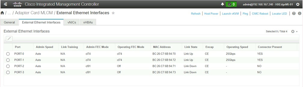
Cisco IMC external Ethernet interfaces
If the link state remains as Link Down, then you may need to modify the FEC settings of the switch interfaces or Cisco ACI policy, and you may need to make changes through the IMC command-line interface (CLI) of the HX-Series servers. For 25 Gigabit Ethernet connections, the FEC mode of the interfaces on the switches and VICs must match, and they must be modes supported by the transceivers. Do not continue with the Cisco HyperFlex installation until the two links for each HX-Series server are all shown as Link Up.
If you need to modify the FEC mode of the VIC cards on the HX-Series servers' IMC through the CLI, refer to the following instructions: https://www.cisco.com/c/en/us/td/docs/unified_computing/ucs/c/sw/cli/config/guide/4_0/b_Cisco_UCS_C-Series_CLI_Configuration_Guide_40/b_Cisco_UCS_C-Series_CLI_Configuration_Guide_40_chapter_01001.html.
Additional information regarding Cisco ACI switches and their autonegotiation and FEC settings and capabilities can be found here: https://www.cisco.com/c/en/us/td/docs/switches/datacenter/aci/apic/sw/kb/b_Cisco_ACI_and_Forward_Error_Correction.html.
Additional information regarding Cisco 25 Gigabit Ethernet transceivers, along with their supported FEC modes, can be found here: https://www.cisco.com/c/en/us/products/collateral/interfaces-modules/transceiver-modules/datasheet-c78-736950.html.
Install Cisco HyperFlex DC-No-FI
Most of the prerequisites and installation steps for a Cisco HyperFlex DC-No-FI cluster are identical to those for a Cisco HyperFlex Edge cluster, with two notable exceptions:
● The initial cluster installation type chosen in the Cisco Intersight platform
● The recommendation to enable jumbo frames for the storage network
Cisco Intersight platform
Begin the installation of a Cisco HyperFlex DC-No-FI cluster by selecting the Datacenter option and then deselecting the Use Fabric Interconnect checkbox (Figure 9).
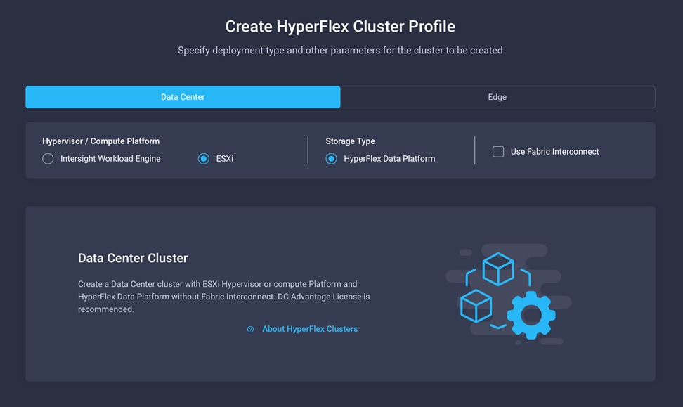
Cisco HyperFlex DC-No-FI installation in Cisco Intersight platform
Enable jumbo frames
Because the Cisco HyperFlex DC-No-FI deployment is intended for use running data center–class workloads, the system should be configured for the maximum possible performance. One key consideration is the use of jumbo frames for the node-to-node Cisco HyperFlex HX Data Platform storage traffic on the storage VLAN. Testing has shown that enabling jumbo frames can improve overall storage performance of the system significantly and achieve performance of within 1 to 2 percent of the performance achieved using the Cisco fabric interconnects when properly configured. Jumbo frames can be enabled only in environments in which all connections to the uplink switches are capable of passing jumbo frames and all ports on the switches are properly configured to pass jumbo frames. In addition, in specific failure and failover scenarios Cisco HyperFlex storage traffic must be able to move from upstream switch A to upstream switch B. Therefore, jumbo frames must also be able to traverse the upstream switches’ uplinks to reach one another. Because each make and model of upstream switch is different, this document does not provide specific instructions about how to enable jumbo frames.
Prior to beginning the Cisco HyperFlex installation process, you should have verified that the network interfaces of the upstream switches for the HX-Series nodes and the upstream switches’ uplinks are all configured to allow jumbo frames. Next, ensure that the option for using jumbo frames is selected during the installation through Cisco Intersight in the Cluster Network Policy settings area (Figure 10).
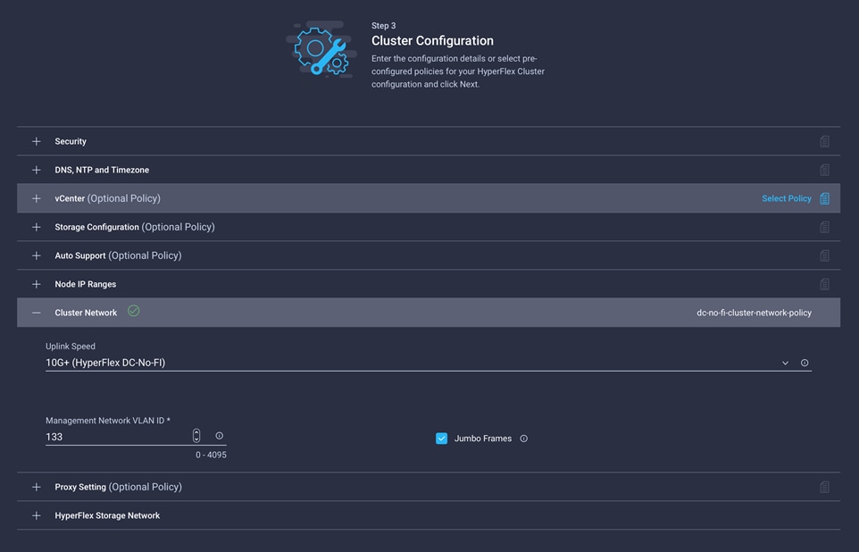
Cisco HyperFlex DC-No-FI jumbo frames configured in Cisco Intersight platform
Configure quality-of-service policy
As a software-defined storage solution, Cisco HyperFlex nodes send storage I/O traffic to one another through their shared Ethernet storage network for every storage transaction. To help ensure the best possible performance, this node-to-node storage traffic must move at the highest possible speed with the lowest possible latency. The HX-Series rack servers are connected to the upstream switches through a pair of converged Ethernet links, which carry not only the node-to-node storage traffic, but all guest virtual machine, management, external iSCSI, replication, and vMotion traffic as well. This converged traffic can lead to congestion on the links, which could delay storage I/O transactions and hamper the overall Cisco HyperFlex performance. By design, the Cisco HyperFlex system places all storage traffic on the B-side switch, and it places much of the other traffic on the A-side switch during normal operations. However, the guest virtual machine traffic is spread across both switches for maximum bandwidth and faster failover. Because to this configuration, in some scenarios large numbers of guest virtual machine traffic may generate a high amount of storage traffic, or traffic may simply be occurring simultaneously with a high storage I/O load, leading to congestion, which can result in an overall slowdown of the system.
Cisco recommends that, whenever possible, you should implement quality-of-service (QoS) policy for Cisco HyperFlex node-to-node traffic to mitigate the impact should network congestion occur. The standard Cisco HyperFlex system implements QoS as part of the fabric interconnect configuration, but this is not available as part of the DC-No-FI deployment. Therefore, you must implement the configuration manually on the HX-Series nodes and in the configuration of the upstream switches.
Note that QoS configurations can be complex in large organizations and could result in unexpected behavior if not implemented correctly. Thus, although examples are given here, the networking team in your organization must review the settings and make the best decisions for the traffic in your own network. For example, Cisco ACI fabrics use a single QoS policy for the entire fabric; therefore, changes to accommodate a Cisco HyperFlex system could negatively impact other systems.
In general, the configuration requires you to set a specific class of service (CoS) on the HX-Series nodes’ storage virtual NIC (vNIC) interface and match that CoS to a class map and policy map, which would define the relative weight of the traffic, or to place the traffic into a predefined priority queue. The example that follows generally mimics the configuration set when fabric interconnects are used: that is, setting storage traffic as CoS 5 and then placing that traffic in the priority 1 queue on the upstream Cisco switches running in Cisco NX-OS mode, which is unblocked by any other traffic and cannot be dropped. This configuration should be sufficient, as long as the upstream switches are not carrying any other traffic that also uses CoS 5 and that simultaneously requires a different weight or priority.
Because there are so many different combinations and requirements for QoS implementations, it is impossible to describe all scenarios and permutations, so the settings that follow are given only as examples of what is possible when you use QoS for the Cisco HyperFlex DC-No-FI system.
Configure CoS on the vNIC storage interfaces
You cannot configure QoS on the Cisco HyperFlex DC-No-FI system through the Cisco Intersight platform. Instead, you must implement the configuration manually after the Cisco HyperFlex system is installed. Before you configure the QoS policies on the network, the storage interfaces of the Cisco HyperFlex nodes must be configured to be tagged with a CoS. In the example here, the interfaces are tagged as CoS 5, which will then be used to match the class map and policy map of the Cisco switches connected to the servers.
This is the process for configuring CoS on the Cisco HyperFlex storage interface:
1. Using a web browser, log in to the Cisco HX-Series server’s IMC management interface as a user with admin rights.
2. From the navigation menu, choose Networking. Then click Adapter Card (MLOM).
3. Click the vNICs tab.
4. Click vNIC eth2, named storage-data-a. Enter 5 in the Class of Service field and then click the Save Changes button (Figure 11).
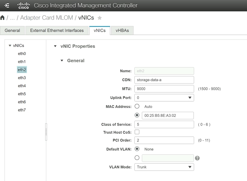
Configuring CoS
5. Click vNIC eth3, named storage-data-b. Enter 5 in the Class of Service field and then click the Save Changes button.
6. Log out of the IMC management interface.
7. Repeat steps 1 through 6 for each remaining server in the Cisco HyperFlex DC-No-FI cluster.
Example of Cisco NX-OS switch configuration
The following example shows a configuration for a Cisco Nexus® switch running in Cisco NX-OS mode. This configuration defines a class map and policy map to match CoS 5 and then creates a queueing policy map that places CoS 5–tagged traffic into the priority 1 queue. The policy maps are then applied to the interface of the switch to which the Cisco HX-Series node is connected so that the incoming storage traffic from the Cisco HyperFlex node can be identified and prioritized according to the policy. You would need to repeat this process for all interfaces connected to the servers in the cluster, across both switches.
N91380-B(config)# class-map type qos hx_cos5
N91380-B(config-cmap-qos)# match cos 5
N91380-B(config-cmap-qos)# exit
N91380-B(config)# policy-map type qos hx_qos
N91380-B(config-pmap-qos)# class type qos hx_cos5
N91380-B(config-pmap-c-qos)# set qos-group 5
N91380-B(config-pmap-c-qos)# exit
N91380-B(config-pmap-qos)# exit
N91380-B(config)# policy-map type queuing prio1
N91380-B(config-pmap-que)# class type queuing c-in-q5
N91380-B(config-pmap-c-que)# priority level 1
N91380-B(config-pmap-c-que)# exit
N91380-B(config-pmap-que)# exit
N91380-B(config)# int e1/1-16
N91380-B(config-if)# service-policy type qos input hx_qos
N91380-B(config-if)# service-policy type queuing input prio1
N91380-B(config-if)# end
Example of Cisco ACI QoS configuration
The example in Figure 12 and Figure 13 shows a possible QoS configuration for a Cisco ACI fabric using the Cisco Application Policy Infrastructure Controller (APIC). A typical Cisco ACI design will contain an endpoint group (EPG) defined for the Cisco HyperFlex storage VLAN with the HX-Series nodes as members. The EPG for Cisco HyperFlex storage can then be configured to use a specific QoS class defined in the overall Cisco ACI fabric. The chosen QoS class can be tailored to use relative weights or strict priority across the fabric. However, you must use care when designing the QoS class settings because they apply to the entire Cisco ACI fabric. In most cases, you also need to enable the setting to preserve the CoS tags across the network within the QoS class settings. This setting helps ensure that QoS weights and priorities are carried forward through the fabric for the Cisco HyperFlex storage traffic, a process that may be necessary in certain failover situations.
For additional information and a detailed explanation of Cisco ACI and QoS for Cisco HyperFlex, refer to the following document: https://www.cisco.com/c/dam/en/us/products/collateral/hyperconverged-infrastructure/hyperflex-hx-series/qos-for-hyperflex-wp.pdf.
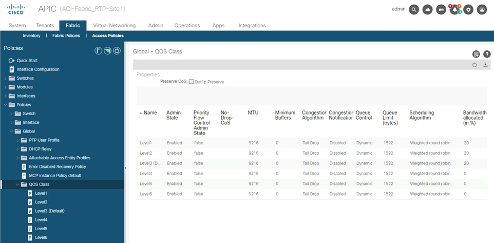
Cisco ACI QoS class settings
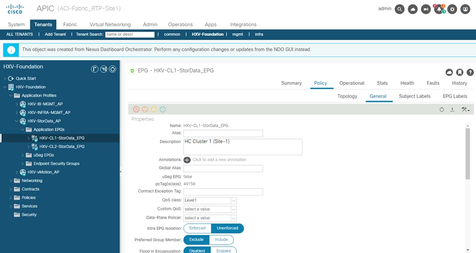
Cisco ACI EPG settings
Spanning tree
By default, in a Cisco HyperFlex cluster managed by Cisco fabric interconnects, all server interfaces are endpoints that do not participate in spanning tree. In contrast, a Cisco HyperFlex DC-No-FI system can be connected to a variety of upstream switches that may have spanning tree enabled by default. Spanning-tree convergence delays can cause problems with Cisco HyperFlex systems during node reboots for upgrades or planned maintenance. To mitigate this potential problem, you should configure all interfaces connecting to Cisco HyperFlex HX-Series rack-mount servers in a DC-No-FI cluster for portfast, so that the interfaces come online immediately.
Cisco NX-OS spanning-tree portfast
To enable portfast on a Cisco switch in NX-OS mode, configure all the Cisco HyperFlex nodes’ interfaces through the command line as an edge trunk:
N93180-A# conf
Enter configuration commands, one per line. End with CNTL/Z.
N93180-A(config)# interface e1/1
N93180-A(config-if)# spanning-tree port type edge trunk
Cisco ACI spanning-tree portfast
Cisco ACI fabrics do not use Spanning Tree Protocol. Therefore, interfaces should establish a link immediately. For additional safety, interface groups can be configured with a Bridge Protocol Data Unit (BDPU) filter, so that all BDPU packets will be dropped and ignored, although Cisco HyperFlex nodes should never generate any BDPU packets.
Cisco HyperFlex DC-No-FI deployments give customers the flexibility to determine the right hardware configuration to meet the needs of their storage and application profiles. By allowing customers to deploy higher-performance server models at a larger scale without the need for Cisco UCS fabric interconnects, customers can achieve data center–class performance in a modern hyperconverged platform at a lower cost and with smaller footprint while using existing network hardware. The installation process for Cisco HyperFlex systems is highly automated through the Cisco Intersight platform. Nevertheless, customers must take care to properly configure the existing networking equipment to achieve the maximum possible performance from the system.
To find complete information and details regarding the Cisco HyperFlex product portfolio, visit: https://www.cisco.com/site/us/en/products/computing/hyperconverged-infrastructure/index.html
For comments and suggestions about this guide and related guides, join the discussion on Cisco Community at https://cs.co/en-cvds.
About the Cisco Validated Design program
The Cisco® Validated Design (CVD) program consists of systems and solutions designed, tested, and documented to facilitate faster, more reliable, and more predictable customer deployments. For more information, go to http://www.cisco.com/go/designzone.
Cisco Validated Design program
ALL DESIGNS, SPECIFICATIONS, STATEMENTS, INFORMATION, AND RECOMMENDATIONS (COLLECTIVELY, "DE-SIGNS") IN THIS MANUAL ARE PRESENTED "AS IS," WITH ALL FAULTS. CISCO AND ITS SUPPLIERS DISCLAIM ALL WAR-RANTIES, INCLUDING, WITHOUT LIMITATION, THE WARRANTY OF MERCHANTABILITY, FITNESS FOR A PARTICULAR PURPOSE AND NONINFRINGEMENT OR ARISING FROM A COURSE OF DEALING, USAGE, OR TRADE PRACTICE. IN NO EVENT SHALL CISCO OR ITS SUPPLIERS BE LIABLE FOR ANY INDIRECT, SPECIAL, CONSEQUENTIAL, OR INCIDENTAL DAMAGES, INCLUDING, WITHOUT LIMITATION, LOST PROFITS OR LOSS OR DAMAGE TO DATA ARISING OUT OF THE USE OR INABILITY TO USE THE DESIGNS, EVEN IF CISCO OR ITS SUPPLIERS HAVE BEEN ADVISED OF THE POSSIBILITY OF SUCH DAMAGES.
THE DESIGNS ARE SUBJECT TO CHANGE WITHOUT NOTICE. USERS ARE SOLELY RESPONSIBLE FOR THEIR APPLICA-TION OF THE DESIGNS. THE DESIGNS DO NOT CONSTITUTE THE TECHNICAL OR OTHER PROFESSIONAL ADVICE OF CISCO, ITS SUPPLIERS OR PARTNERS. USERS SHOULD CONSULT THEIR OWN TECHNICAL ADVISORS BEFORE IMPLE-MENTING THE DESIGNS. RESULTS MAY VARY DEPENDING ON FACTORS NOT TESTED BY CISCO.
CCDE, CCENT, Cisco Eos, Cisco Lumin, Cisco Nexus, Cisco StadiumVision, Cisco TelePresence, Cisco WebEx, the Cisco logo, DCE, and Welcome to the Human Network are trademarks; Changing the Way We Work, Live, Play, and Learn and Cisco Store are service marks; and Access Registrar, Aironet, AsyncOS, Bringing the Meeting To You, Catalyst, CCDA, CCDP, CCIE, CCIP, CCNA, CCNP, CCSP, CCVP, Cisco, the Cisco Certified Internetwork Expert logo, Cisco IOS, Cisco Press, Cisco Systems, Cisco Systems Capital, the Cisco Systems logo, Cisco Unified Computing System (Cisco UCS), Cisco UCS B-Series Blade Servers, Cisco UCS C-Series Rack Servers, Cisco UCS S-Series Storage Servers, Cisco UCS Manager, Cisco UCS Management Software, Cisco Unified Fabric, Cisco Application Centric Infrastructure, Cisco Nexus 9000 Series, Cisco Nexus 7000 Series. Cisco Prime Data Center Network Manager, Cisco NX-OS Software, Cis-co MDS Series, Cisco Unity, Collaboration Without Limitation, EtherFast, EtherSwitch, Event Center, Fast Step, Follow Me Browsing, FormShare, GigaDrive, HomeLink, Internet Quotient, IOS, iPhone, iQuick Study, LightStream, Linksys, MediaTone, MeetingPlace, MeetingPlace Chime Sound, MGX, Networkers, Networking Academy, Network Registrar, PCNow, PIX, PowerPanels, ProConnect, ScriptShare, SenderBase, SMARTnet, Spectrum Expert, StackWise, The Fastest Way to Increase Your Internet Quotient, TransPath, WebEx, and the WebEx logo are registered trade-marks of Cisco Systems, Inc. and/or its affiliates in the United States and certain other countries. (LDW_1)