|
Virtualization QoS Design Considerations
|
|
| |
|
| Introduction |
|
|
This section covers best practices guidelines and recommendations for LAN access for UC VM application traffic (e.g. voice/video media and signaling). This section does NOT cover best practices for storage access (e.g. VM to SAN/NAS-attached array).
|
|
| |
|
| Network Infrastructure Hardware Compatibility |
|
|
"Network Infrastructure" includes elements/devices like routers, LAN switches, gateways, fabric extenders and fabric interconnect switches (where some elements may be virtual instead of physical).
For general considerations, see https://www.cisco.com/c/dam/en/us/td/docs/voice_ip_comm/uc_system/virtualization/virtualization-software-requirements.html#vnetwork_switch. Specific to Cisco fabric extenders (UCS 2100, 2200, 2300 or future models) and fabric interconnect switches (UCS 6100, 6200, 6300 or future models):
|
|
| |
|
| Guidelines for Physical LAN Links, Trunking and Traffic Sizing |
|
|
Physical Links Redundant physical LAN interfaces and redundant physical upstream switches are recommended. Cisco UCS B-Series connect to the LAN via UCS Fabric Interconnect, so use redundant 1Gbps or 10Gbps ports on the UCS Fabric Interconnect to the upstream switches. Cisco UCS C-Series tested reference configurations and Business Edition platforms based on the UCS C-series ship with two, six, or more 1Gbps Ethernet ports (for example, with the UCS C240 M4, two on the motherboard plus eight 1 Gbps ports on PCIe cards). There are no hard requirements on how to configure these Ethernet ports, but as a best practice, configure them in the following manner:
If using specs-based VMware support, other LAN interconnect options may be used, such as using Cisco VIC in NIV mode instead of multiple physical NICs.
Trunking Whether or not you configure the UC VM traffic links as trunks depends on your deployment - UC applications do not mandate this. E.g. if most of your VMs are in the same VLAN, then trunks may not be needed. If you decide to use trunks, 802.1q is recommended over ISL.
VM vNIC traffic can be tagged with 802.1q in case you use a trunk to your VMware host and use a VLAN other than the native VLAN. UC applications do not mandate this, and recall that any tags will be removed by the vSwitch before traffic enters the VM.
LAN Traffic Sizing Besides redundancy, link quantity and speed will depend on aggregate LAN traffic of UC VMs. Most UC VMs have only one or two vNIC's. Each vNIC will use 1Gbps if available, but does not require this much bandwidth. Use the design guides to size UC VM LAN traffic. For example: This traffic sizing can be used to size LAN access links to handle the aggregate bandwidth load of the UC VMs.
VMware NIC teaming There are no specific requirements from the Cisco Collaboration applications perspective on how many virtual switches need to be configured and how to configure VMware NIC teaming (except with UCCE, which has some requirements for the visible and private traffic). Follow the VMware and Cisco switches requirements and configuration guidelines. The following guidelines are not requirements, but just some examples.
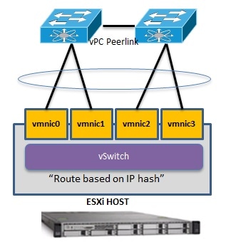
If the upstream switches support virtual Port Channels (vPC)/Virtual Switching System (VSS)/Cisco StackWise, links to the upstream switches could be aggregated together in a EtherChannel and the VMware NIC teaming "Route based on IP hash" policy could be configured.
|
|
| |
|
| QoS Design Considerations for VMs with Cisco UCS B-Series Blade Servers |
|
|
Unified Communications applications such as Cisco Unified Communications Manager (Unified CM) run as virtual machines on top of the VMware Hypervisor. These Unified Communications virtual machines are connected to a virtual software switch rather than a hardware-based Ethernet. The following types of virtual software switches are available:
Distributed VMware vSwitch: Available only with the Enterprise Plus Edition of the VMware ESXi hypervisor. Distributed virtual software switching can span multiple physical blade servers and helps simplify manageability of the software switch. Cisco Nexus 1000V Switch: Cisco has a software switch called the Nexus 1000 Virtual (1000V) Switch. The Cisco Nexus 1000V requires the Enterprise Plus Edition of VMware ESXi. It is a distributed virtual switch visible to multiple VMware hosts and virtual machines. The Cisco Nexus 1000V Series provides policy-based virtual machine connectivity, mobile virtual machine security, enhanced QoS, and network policy. From the virtual connectivity point of view, each virtual machine can connect to any one of the above virtual switches residing on a physical server. UC virtual machine traffic flows from the application, to the virtual machine's vNIC, then to the VMware host's virtual software switch (one of VMware vSwitch, VMware Distributed vSwitch, or Cisco Nexus 1000V Switch), then out a physical adapter. What kind of physical adapter depends on the compute/network hardware in use:
Note that CNA, Cisco VIC, UCS I/O Modules, and UCS FI 6100/6200/6300 carry both the IP and fibre channel SAN traffic via Fibre Channel over Ethernet (FCoE) on a single wire. If using UCS 6100/6200/6300 Fabric Interconnect Switches, it sends IP traffic to an IP switch (for example, Cisco Catalyst or Nexus Series Switch), and it sends SAN traffic to a Fibre Channel SAN Switch (for example, Cisco MDS Series Switch).
|
|
| |
|
| Congestion Scenario |
|
|
In a deployment with Cisco UCS B-Series blades servers and with Cisco Collaboration applications only, network congestion or an oversubscription scenario is unlikely because the UCS Fabric Interconnect Switch provides a high-capacity switching fabric, and the usable bandwidth per server blade far exceeds the maximum traffic requirements of a typical Collaboration application.
However, there might be scenarios where congestion could arise. For example, with a large number of B-Series blade servers and chassis, a large number of applications, and/or third-party applications requiring high network bandwidth, there is a potential for congestion on the different network elements of the UCS B-Series system (adapters, IO Modules, Fabric Interconnects). In addition, FCoE traffic is sharing the same network elements as IP traffic, therefore applications performing a high amount of storage transfer would increase the utilization on the network elements and contribute to this potential congestion.
|
|
| |
|
| QoS Implementation with Cisco UCS B-Series |
|
|
Cisco UCS Fabric Interconnect Switches and adapters such as the Cisco VIC adapter perform QoS based on Layer 2 CoS values. Traffic types are classified by CoS value into QoS system classes that determine, for example, the minimum amount of bandwidth guaranteed and the packet drop policy to be used for each class. However, Cisco Collaboration applications perform QoS marking at Layer 3 only, not at the Layer 2. Hence the need for mapping the L3 values used by the applications to the L2 CoS values used by the Cisco UCS elements.
The VMware vSphere Standard Switch, vSphere Distributed Switch, Cisco UCS Fabric Interconnect switches, and other UCS network elements do not have the ability to perform this mapping between L3 and L2 values. Use the Cisco Nexus 1000V, which like the traditional Cisco switches, can perform this mapping. For example, the Nexus 1000V can map PHB EF (real-time media traffic) to CoS 5 and PHB CS3 (voice/video signaling traffic) to CoS 3.
Note: The decision to use the Nexus 1000V will vary on a case-by-case basis, depending on the available bandwidth for Unified Communications applications within the UCS architecture. If there is a possibility that a congestion scenario will arise, then the Nexus 1000V switch should be deployed.
If the Nexus 1000V is not deployed, it is still possible to provide some QoS, but it would not be an optimal solution. For example, you could create multiple virtual switches and assign a different CoS value for the uplink ports of each of those switches. For example, virtual switch 1 would have uplink ports configured with a CoS value of 1, virtual switch 2 would have uplink ports configured with a CoS value of 2, and so forth. Then the application virtual machines would be assigned to a virtual switch, depending on the desired QoS system class. The downside to this approach is that all traffic types from a virtual machine will have the same CoS value. For example, with a Unified CM virtual machine, real-time media traffic such as MoH traffic, signaling traffic, and non-voice traffic (for example, backups, CDRs, logs, Web traffic, and so forth) would share the same CoS value.
|
|