
New and Changed Information
The following table provides an overview of the significant changes up to this current release. The table does not provide an exhaustive list of all changes or of the new features up to this release.
| Release Version | Feature | Description |
|---|---|---|
|
NDFC release 12.2.1 |
Support for NDFC discovery of IOS-XOR devices without having to configure SNMP |
With this feature, you can discover an IOS-XR device without having to configure the Simple Network Management Protocol (SNMP). NDFC uses Secure Shell (SSH) only for IOS-XR device discovery. For more information, see VRF Lite Between Cisco Nexus 9000 Based Border and Non-Nexus Device. |
VRF Lite
External connectivity from data centers is a prime requirement where workloads that are part of a data center fabric can communicate with an outside fabric over WAN or Backbone services. To enable Layer 3 for north-south traffic flow, use virtual routing and forwarding instances (VRF)-Lite peering between data center border devices and the external fabric edge routers.
A VXLAN (Virtual Extensible Local Area Network) EVPN (Ethernet Virtual Private Network)-based data center fabrics provide connectivity by distributing IP-MAC reachability information among various devices within the fabric. The VRF-Lite feature is used for connecting the fabric to an external Layer 3 domain. This can be a border router or a Border Gateway router.
You can enable VRF Lite on the following devices:
-
Border
-
Border Spine
-
Border Gateway
-
Border Gateway Spine
-
Border Super Spine
For more information on managing and monitoring VXLAN EVPN fabrics, see the Managing and Monitoring VXLAN EVPN Fabrics Using Cisco Nexus Dashboard Fabric Controller (NDFC).
Prerequisites and Guidelines
-
VRF Lite requires Cisco Nexus 9000 Series Cisco Nexus Operating System (NX-OS) Release 7.0(3)I6(2) or later.
-
Familiarity with VXLAN BGP EVPN data center fabric architecture and VXLAN overlay provisioning through NDFC.
-
Fully configured VXLAN BGP EVPN fabrics including underlay and overlay configurations for the various leafs and spine devices, external fabric configuration through NDFC, and relevant external fabric device configuration (edge routers, for example).
-
You can configure VXLAN BGP EVPN fabric (and its connectivity to an external Layer 3 domain for north-south traffic flow) manually or using NDFC.
This document explains the process to connect the fabric to an edge router (outside the fabric, toward the external fabric) through NDFC. So, you must know how to configure and deploy VXLAN BGP EVPN and external fabrics through NDFC.
-
You can enable VRF Lite on a physical ethernet interface or on a Layer 3 port channel. A subinterface over a physical interface or Layer 3 port-channel interface is created in NDFC at the VRF extension moment for each VRF-Lite link for which the VRF is extended over.
-
-
When you create a VXLAN VRF, ensure that you check the following three fields:
Field Description Advertise Host Routes
By default, over the VRF-Lite peering session, only nonhost (/32 or /128) prefixes are advertised. If host routes (/32 or /128) must be enabled and advertised from the border device to the edge/WAN router, check the Advertise Host Routes check box. Route-map does outbound filtering. By default, this check box is disabled.
Advertise Default Route
This field controls whether a network statement 0/0 is enabled under the VRF. This in turn advertises 0/0 route in BGP. By default, this field is enabled. When you choose this check box, this ensures that a 0/0 route is advertised inside the fabric over EVPN route type 5 to the leafs, thereby providing a default route out of the leafs toward the border devices.
Config Static 0/0 Route
By default, this check box is checked. This field controls whether a static 0/0 route to the edge/WAN router must be configured under the VRF on the border device. By default, this field is enabled. If WAN/edge routers are advertising a default route over the VRF-Lite peering to the border device in the fabric, then this field must be disabled. In addition, the Advertise Default Route field must be disabled. The 0/0 route that is advertised over the External Border Gateway Protocol sends over EVPN to the leafs without requiring more configuration. The clean IBGP EVPN separation inside the fabric with eBGP for external out-of-fabric peering provides for this desired behavior.
-
To delete a VRF-Lite IFC, remove all the VRF extensions that are enabled on the IFC. Otherwise an error message displays. After you remove the VRF-Lite attachments, recalculate and deploy the fabric to remove any pending Layer 3 extension configurations. NDFC removes the per-VRF subinterface and per-VRF External Border Gateway Protocol configuration on the devices.
Sample Scenarios
The following sections explain different use cases for configuring VRF Lite:
-
Automatic VRF Lite (IFC) Configuration
-
VRF Lite between Cisco Nexus 9000 based Border and Cisco Nexus 9000 based edge router
-
VRF Lite between Cisco Nexus 9000 based Border and Non-Cisco device
-
VRF Lite between Cisco Nexus 9000 based Border and Non-Nexus device
This is a typical use case of a Cisco ASR 9000-based edge router in managed mode.
Automatic VRF Lite (IFC) Configuration
Guidelines
-
Auto IFC is supported on Cisco Nexus devices only.
-
You can configure Cisco ASR 1000 Series routers and Cisco Catalyst 9000 Series switches as edge routers. To configure, set up a VRF Lite IFC, and connect it as a border device with easy fabric.
-
You can configure Cisco ASR 9000 Series routers as edge routers in managed mode.
-
If the device in the External fabric is non-Nexus, you must create IFC manually.
-
Ensure that no user policy is enabled on the interface that connects to the edge router. If a policy exists, then the interface will not be configured.
-
Autoconfiguration is supported for the following cases:
-
Border role in the VXLAN fabric and Edge Router role in the connected external fabric device
-
Border Gateway role in the VXLAN fabric and Edge Router role in the connected external fabric device
-
Border role to another Border role directly

Autoconfiguration is not provided between two Border Gateways (BGWs).
If VRF Lite is required between other roles, you must deploy it manually on the NDFC Web UI.
-
-
To deploy configurations in the external fabric, you must uncheck the Fabric Monitor Mode check box in the external fabric settings. When an external fabric is set to Fabric Monitor Mode Only, you cannot deploy configurations on the switches.
Easy Fabric Settings
The following are the two modes in which you can deploy VRF Lite. By default, VRF-Lite deployment is set to Manual. You can change the settings based on your requirement.
| Field | Description |
|---|---|
|
Manual |
Use this option to deploy the VRF Lite IFCs manually between the source and the destination devices. |
|
Back2Back&ToExternal |
Use this option to automatically configure VRF Lite IFCs between a border switch and the edge or core switches in external fabric or between back-to-back border switches in VXLAN EVPN fabric.
Though VRF-Lite mode is set to Manual for NDFC resource handling, a Data Center Interconnectivity (DCI) subnet is required. The Manual mode is the default mode in fabric settings. To change the default mode to another mode, click Edit fabric settings. On the Resource tab, modify the VRF Lite Deployment field to the above mentioned auto configuration modes. |
|
Auto Deploy Peer |
This check box is applicable for VRF-Lite deployment. When you check this check box, IFCs are automatically created for peer devices. You can check or uncheck this check box when the VRF Lite Deployment field is not set to Manual. The value you choose takes priority. This configuration only affects the new auto-created IFCs and does not affect the existing IFCs. |
|
Auto Deploy Default VRF |
When you select this check box, the Auto Generate Configuration on default VRF field is automatically enabled for auto-created VRF Lite IFCs. You can check or uncheck this checkbox when the VRF Lite Deployment field is not set to Manual. The Auto Generate Configuration on default VRF field when set, automatically configures the physical interface for the border device in the default VRF, and establishes an EBGP connection between the border device and the edge device or another border device in a different VXLAN EVPN fabric. |
|
Auto Deploy Default VRF for Peer |
When you select this check box, the Auto Generate Configuration for NX-OS Peer on default VRF field is automatically enabled for auto-created VRF Lite IFCs. You can check or uncheck this check box when the VRF Lite Deployment field is not set to Manual. The Auto Generate Configuration for NX-OS Peer on default VRF field when set, automatically configures the physical interface and the EBGP commands for the peer NX-OS switch.
You can access the Auto Generate Configuration on default VRF and Auto Generate Configuration for NX-OS Peer on default VRF fields for an IFC link by navigating to Actions > Edit > VRF Lite. |
|
Redistribute BGP Route-map Name |
Defines the route map for redistributing the BGP routes in default VRF. |
|
VRF Lite Subnet IP Range |
The IP address for VRF Lite IFC deployment is chosen from this range. The default value is 10.33.0.0/16. Ensure that each fabric has its own unique range and is distinct from any underlay range to avoid possible duplication. These addresses are reserved with the Resource Manager. |
|
VRF Lite Subnet Mask |
By default, it is set to /30, which is a best practice for point-to-point (P2P) links. |
VRF Lite Between Cisco Nexus 9000 Based Border and Cisco Nexus 9000 Based Edge Router
In the following example topology, the DC-VXLAN fabric is connected to a WAN-VXLAN cloud. The easy fabric has a border leaf role and the WAN-VXLAN cloud has a device with the role edge router. NDFC shows the physical and logical representation of the topology with Cisco Discovery Protocol/Link Layer Discovery Protocol (LLDP) link discovery.
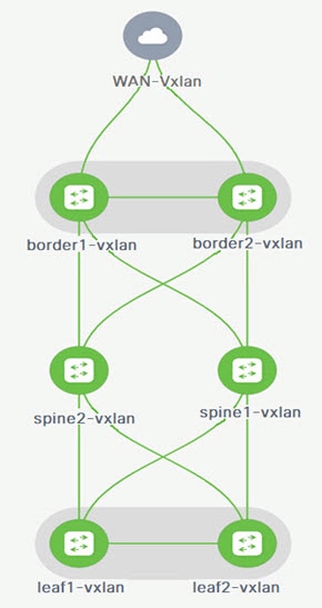
In this example, you can enable VRF-Lite connections between a DC-VXLAN border leaf and a WAN-VXLAN edge router.
For a VRF-Lite configuration, you must enable External Border Gateway Protocol (EBGP) peering between the fabric’s border interfaces and the edge router’s interfaces, through point-to-point (P2P) connections.
The border physical interfaces are:
-
eth1/1 on border1-Vxlan, toward eth1/1 on WAN1-Vxlan.
-
eth1/2 on border2-Vxlan, toward eth1/2 on WAN1-Vxlan.
Workflow for Configuring an IPv4 or an IPv6 Overlay Network
-
Create an inter-fabric connection using source and destination IPv4 or IPv6 addresses.
For more information, see Verify a VRF-Lite Configuration.
-
Add a VRF-Lite extension.
-
Attach the VRF and the VRF-Lite extension to the border device.
For more information, see Attach the VRF and the VRF-Lite Extension to the Border Device.
-
Create a network configured with an IPv4 or an IPv6 gateway.
For more information, see the section "Creating Network for Standalone Fabrics" in About Fabric Overview for LAN Operational Mode Setups.
-
Recalculate and deploy the configuration.
Verify a VRF-Lite Configuration
-
Verify the links between the border and the edge router.
-
Choose Manage > Fabrics and double-click on a DC-VXLAN fabric.
On the Fabric Overview page, click the Links tab.
-
Verify that NDFC detects the links and the ext_fabric_setup policy is assigned automatically.
-
Select the fabric name and choose Actions > Edit.
Field Description Link Type
Specifies the interfabric connection (IFC) link between two different fabrics within NDFC. By default, the Inter-Fabric option displays.
Link Sub-Type
Specifies the subtype of link. By default, the VRF_LITE option displays.
Link Template
Specifies the template for the link. The default template for a VRF-Lite IFC is ext_fabric_setup. The template enables the source and destination interfaces as Layer 3 interfaces, configures the no shutdown command, and sets the Maximum Transmission Unit (MTU) value to 9216.
Source Fabric
NDFC autodetects and populates the Source Fabric field based on the Cisco Discovery Protocol or LLDP discovery.
Destination Fabric
NDFC autodetects and populates the Destination Fabric field based on the Cisco Discovery Protocol or LLDP discovery.
Source Interface
NDFC autodetects and populates the Source Interface field based on the Cisco Discovery Protocol or LLDP discovery.
Destination Device
NDFC autodetects and populates the Destination Device field based on the Cisco Discovery Protocol or LLDP discovery.
Source Interface
NDFC autodetects and populates the Source Interface field based on the Cisco Discovery Protocol or LLDP discovery.
Destination Interface
NDFC autodetects and populates the Destination Interface field based on the Cisco Discovery Protocol or LLDP discovery.
-
Enter the necessary field values to configure an inter-fabric link.
The tabs and their fields on the page are explained in the following sections.
-
When you have completed the necessary configurations, click Save.
General Parameters
The General Parameters tab is displayed by default. The fields in this tab are described in the following table.
| Field | Description |
|---|---|
|
Source BGP ASN |
Specifies the Border Gateway Protocol (BGP) Autonomous System Number (ASN) for the selected source fabric. |
|
Source IP Address/Mask |
Specifies the NDFC auto allocated IP pool from the resource manager pool of the VRF-Lite subnet pool for the Ethernet1/1 subinterface, the source interface of the IFC. A subinterface is created for each VRF extended over this IFC, and a unique 802.1Q ID is assigned to it. The IP address/mask entered here, along with the BGP neighbor IP field (explained below) is used as the default value for the subinterface that is created as a VRF extension and can be overwritten. For example, an 802.1Q ID of 2 is associated with subinterface Eth 1/1.2 for VRF corporate traffic, and 802.1Q ID of 3 is associated with Eth 1/1.3 and VRF engineering, and so on. The IP prefix is reserved by the NDFC resource manager. Ensure that you use a unique IP address prefix for each IFC you create in the topology. |
|
Destination IP Address |
Specifies the NDFC auto allocated IP pool from the resource manager pool of the VRF-Lite subnet pool. This is a BGP neighbor IP on the device. Inter-fabric traffic from different VRFs for an IFC with the same source IP address (10.33.0.1/30) and destination IP address (10.33.0.2) as an example. |
|
Source IPv6 Address/Mask |
Specifies the source IPv6 address and mask if you are configuring an IPv6-only inter-fabric link or a dual stack (IPv6 and IPv4) inter-fabric link. |
|
Destination IPv6 Address |
Specifies the destination IPv6 address if you are configuring an IPv6-only inter-fabric link or a dual stack (IPv6 and IPv4) inter-fabric link. |
|
Destination BGP ASN |
Specifies the BGP ASN of the selected destination fabric. |
|
Link MTU |
Specifies the default MTU value of 9216. |
|
Auto Generate Configuration for Peer |
Specifies to auto generate a VRF-Lite configuration for managed NX-OS neighbor devices. This knob autoconfigures the neighbor VRF on the neighboring managed device. For example, NDFC automatically creates a VRF on the edge router inside the WAN-Vxlan external fabric. |
What’s next: Complete the configurations in another tab if necessary, or click Save when you have completed the necessary configurations for this link.
Advanced
Enter the following details in The Advanced tab. The fields in this tab are described in the following table:
| Field | Description |
|---|---|
|
Source Interface Description |
Enter a description for the source interface. |
|
Destination Interface Description |
Enter a description for the destination interface. |
|
Source Interface Freeform Config |
Specifies a freeform configuration for the source interface. |
|
Destination Interface Freeform Config |
Specifies a freeform configuration for the destination interface. |
|
Template for Configuration Generation on Peer |
Specifies a Python template for VRF-Lite configuration on an NX-OS peer in an external fabric. This is an auto populated field. |
What’s next: Complete the configurations in another tab if necessary, or click Save when you have completed the necessary configurations for this link.
Default VRF
Enter the following details in the Default VRF tab.
| Field | Description |
|---|---|
|
Auto Generate Configuration on default VRF |
Automatically configures the physical interface for the border device for the default VRF. Establishes an External Border Gateway Protocol (EBGP) connection between the border device and its peer in the VRF-LITE IFC (edge router or another border device in a different VXLAN EVPN fabric). |
|
Auto Generate Configuration for NX-OS/IOS XE Peer on default VRF |
Automatically configures the physical interface and the BGP commands for the NX-OS or the IOS XE peer switch corresponding to the default VRF. |
|
Redistribute BGP Route-map Name |
Defines the route map used for redistributing the BGP routes in the default VRF. |
|
Default VRF BGP Neighbor Password |
Allows you to provide additional security by specifying a password for the BGP neighbor. |
|
Default VRF BGP Password Key Encryption Type |
Specifies the encryption type for the BGP password. |
|
VRF Name in NX-OS Peer Switch |
Enables you to provide a name for the VRF in the peer switch. By default, the peer device is configured with the default VRF, if left blank. |
|
Enable DCI tracking |
Enables Data Center Interconnectivity (DCI) tracking on the physical interface, which allows you to use an existing VRF-Lite link as the VXLAN EVPN multi-site underlay link. Note that you must enable this option only on a border gateway device. |
|
Routing TAG |
Specifies the routing tag associated with the interface IP for the default VRF.
All the configuration changes made to the devices as a result of the above configurations are displayed on the Pending Config page. |
Click Save to save the configuration.
Attach the VRF and the VRF-Lite Extension to the Border Device
-
Click the VRFs tab.
-
Double-click on a VRF Name.
The VRF Overview page displays.
-
Click the VRF Attachments tab.
-
Choose a VRF Name and click Actions > Edit.
The Edit VRF Attachment page appears.
-
You can edit details in the Extension table.
-
Toggle the knob to Attach.
-
In Extend, choose VRF_LITE from the drop-down list.
-
In the Extension table, choose one switch at a time and click Edit.
-
Enter the details for PEER_VRF_NAME.
This auto deploys the VRF on the neighboring device.
When you extend a VRF-Lite consecutive scenario, the VRF must be in the peer fabric and the VRF name must be the same. If the VRF is not in the peer fabric and if you try to extend VRF Lite, an error message is generated displaying the issue.
When you extend VRF Lite between an easy fabric and an external fabric, the VRF name can be the same as the name of the source fabric, or default name, or another VRF name.
-
Enter the required VRF name in the PEER_VRF_NAME field.
The child Policy Template Instances (PTIs) for subinterface, VRF creation, and BGP peering on the external fabric have source values that are populated in the PTI. You cannot edit or delete the policies.
-
Follow the above procedure for adding other inter-fabric links.
-
On the Edit page, click Attach-All, to attach the required VRF extension to the border device.
-
Click Save.
Recalculate and Deploy the Configuration on a VXLAN EVPN Easy Fabric
-
On the Fabric page, double-click on the appropriate fabric to navigate to the Fabric Overview page.
-
Click Actions > Recalculate & Deploy.
-
Perform the same operation by choosing the required VRF Name on the VRF Attachments tab and clicking Actions > Deploy to initiate the VRF or VRF-Lite configuration on the border device.
-
Alternatively, on the Fabric page, click Actions > Recalculate and Deploy.
You can also choose the VRF attachment, edit, and click Deploy.
NDFC pushes VRF and VRF-Lite configurations to the border devices.
Recalculate and Deploy the Configuration on an External Fabric
Choose the external fabric and follow the same procedure.
VRF Lite Between Cisco Nexus 9000 Based Border and Non-Cisco Device
This section describes the procedure for enabling a VRF-Lite connection between a VXLAN EVPN border leaf device and a non-Cisco device in an external fabric.
We recommend using the meta definition of a device instead of importing devices in an external fabric. This allows VRF-Lite configurations to extend Cisco Nexus 9000-managed border devices in an easy fabric. NDFC does not manage destination non-Cisco devices. You must configure the relevant VRF-Lite configuration on the destination device.
Create New IFC Links Between a Border Device and an Edge Router
-
On the Manage > Fabrics page, double-click on a VXLAN EVPN fabric.
The Fabric Overview page appears.
-
Navigate to the Links tab.
-
On the Links tab, click Actions > Create.
The Link Management - Create Link page appears.
-
Enter the following required parameters.
Field Description Link Type
Specifies the inter-fabric connection (IFC) link between two different fabrics within NDFC. By default, the Inter-Fabric option displays.
Link Sub-Type
Specifies the subtype of the link. By default, the VRF_LITE option displays.
Link Template
Specifies the template for the link. The default template for a VRF-Lite IFC is ext_fabric_setup. The template enables the source and destination interfaces as Layer 3 interfaces, configures the no shutdown command, and sets the Maximum Transmission Unit (MTU) value to 9216.
Source Fabric
Select the Source Fabric. This is the easy fabric where a Cisco Nexus 9000 based border device resides.
Destination Fabric
Select any external or Classic LAN fabric. The fabric can be in monitor mode as well.
Source Device
Select the Source Device. This is the Cisco Nexus 9000 based border device.
Destination Device
You can create a "meta device definition". Type any name and click Save. For example, non-cisco.
Source Interface
Select the interface on the border device where the non-cisco device is connected.
Destination Interface
You can create a "meta device interface". Type any interface name and click Save. For example, gig1, tengig1/10, eth1/1 are the valid interface names.
The tabs and their fields on the page are explained in the following sections.
-
When you have completed the necessary configurations, click Save.
General Parameters
The General Parameters tab is displayed by default. The fields in this tab are described in the following table.
| Field | Description |
|---|---|
|
Source BGP ASN |
Specifies the Border Gateway Protocol (BGP) Autonomous System Number (ASN) for the selected source fabric. |
|
Source IP Address/Mask |
Specifies the IP address and mask for the Ethernet1/5 subinterfaces, the source interface of the IFC. The subinterface is created for each VRF extended over this IFC, and a unique 802.1Q ID is assigned to it. The IP address/mask entered here, along with the BGP Neighbor IP field (explained below) used as the default value for the subinterface that is created as a VRF extension and can be overwritten. For example, an 802.1Q ID of 2 is associated with subinterface Eth 1/5.2 for VRF CORP traffic, and 802.1Q ID of 3 is associated with Eth 1/5.3 and VRF ENG, and so on. The IP prefix is reserved with the NDFC resource manager. Ensure that you use a unique IP address prefix for each IFC you create in the topology. |
|
Destination IP Address |
Specifies the NDFC auto allocated IP pool from the resource manager pool of the VRF-Lite subnet pool. This is a BGP neighbor IP on the device. Interfabric traffic from different VRFs for an IFC with the same source IP address (10.33.0.1/30) and destination IP address (10.33.0.2) as an example. |
|
Source IPv6 Address/Mask |
Specifies the source IPv6 address and mask if you are configuring an IPv6-only inter-fabric link or a dual stack (IPv6 and IPv4) inter-fabric link. |
|
Destination IPv6 Address |
Specifies the destination IPv6 address if you are configuring an IPv6-only inter-fabric link or a dual stack (IPv6 and IPv4) inter-fabric link. |
|
Destination BGP ASN |
Specifies the BGP ASN of the selected destination fabric. |
|
Link MTU |
Specifies the default MTU value of 9216. |
|
Auto Deploy Flag |
Not applicable as the destination device is a non-Nexus and a non-Cisco device. |
Advanced
Enter the following details in the Advanced tab. The fields in this tab are described in the following table.
| Field | Description |
|---|---|
|
Source Interface Description |
Enter a description for the source interface. |
|
Destination Interface Description |
Enter a description for the destination interface. |
|
Source Interface Freeform Config |
Specifies a freeform configuration for the source interface. |
|
Destination Interface Freeform Config |
Specifies a freeform configuration for the destination interface. |
|
Template for Configuration Generation on Peer |
Specifies a Python template for VRF-Lite configuration on an NX-OS peer in an external fabric. This is an auto populated field. |
What’s next: Complete the configurations in another tab if necessary, or click Save when you have completed the necessary configurations for this link.
Default VRF
Enter the following details in the Default VRF tab. The fields in this tab are described in the following table.
| Field | Description |
|---|---|
|
Auto Generate Configuration on default VRF |
Automatically configures the physical interface for the border device for the default VRF. Establishes an External Border Gateway Protocol (EBGP) connection between the border device and its peer in the VRF-LITE IFC (edge router or another border device in a different VXLAN EVPN fabric). |
|
Auto Generate Configuration for NX-OS/IOS XE Peer on default VRF |
Automatically configures the physical interface and the BGP commands for the NX-OS or the IOS XE peer switch corresponding to the default VRF. |
|
Redistribute BGP Route-map Name |
Defines the route map used for redistributing the BGP routes in the default VRF. |
|
Default VRF BGP Neighbor Password |
Allows you to provide additional security by specifying a password for the BGP neighbor. |
|
Default VRF BGP Password Key Encryption Type |
Specifies the encryption type for the BGP password. |
|
VRF Name in NX-OS Peer Switch |
Enables you to provide a name for the VRF in the peer switch. By default, the peer device is configured with the default VRF, if left blank. |
|
Enable DCI tracking |
Enables Data Center Interconnectivity (DCI) tracking on the physical interface, which allows you to use an existing VRF-Lite link as the VXLAN EVPN multi-site underlay link. Note that you must enable this option only on a border gateway device. |
|
Routing TAG |
Specifies the routing tag associated with the interface IP for the default VRF.
All the configuration changes made to the devices as a result of the above configurations are displayed on the Pending Config page. |
Click Save to create a new link with the parameters mentioned.
Attach the VRF and the VRF-Lite Extension to the Border Device
-
On the Manage > Fabrics page, double-click on the VXLAN EVPN fabric.
-
On the Fabric Overview page, navigate to the VRFs tab.
-
Double-click on a VRF Name.
The VRF Overview page displays.
-
Click the VRF Attachments tab.
-
Choose a VRF Name and click Actions > Edit.
The Edit VRF Attachment page displays.
-
Click Attach-All to attach the required VRF-Lite extension to the border device and then click Save.
Recalculate and Deploy the Configuration on the VXLAN EVPN Easy Fabric
-
On the Manage > Fabrics page, double-click on the appropriate fabric to navigate to the Fabric Overview page.
-
Click Actions > Recalculate & Deploy.
-
Perform the same action by choosing the required VRF Name on the VRF Attachments tab and clicking Actions > Deploy to initiate the VRF or VRF-Lite configuration on the border device.
VRF Lite Between Cisco Nexus 9000 Based Border and Non-Nexus Device
In this example, you can enable VRF-Lite connections between a DC-VXLAN border leaf and a non-Nexus device in an external fabric.
Before Cisco NDFC Release 12.0.1a, ASR 9000 was supported for an external fabric in monitor mode only. From Release 12.0.1a, ASR 9000 is supported in managed mode with an edge router role.
The following are the supported platforms:
-
ASR 9000
-
NCS 5501 and NCS 5001
-
Cisco 8000
Configuration compliance is enabled for IOS XR switches in an external fabric, similar to Cisco Nexus switches configured on an external fabric. NDFC pushes the configuration at the end of the deployment.
Ensure that the VXLAN BGP EVPN border device is active.
-
Navigate to Manage > Fabrics to create an external fabric.
-
Choose Create Fabric from the Actions Drop-Down List.
-
Enter a name for the external fabric.
-
Choose a fabric type on the Select Type of Fabric page.
-
On the Create Fabric page, enter the appropriate ASN number, uncheck the Fabric Monitor Mode check box, and then click Save.
-
Navigate to the Manage > Inventory > Switches tab and click Actions > Add Switches.
Beginning with NDFC 12.2.1, you do not need to configure the Simple Network Management Protocol (SNMP) for IOS-XR discovery of switches. NDFC uses Secure Shell (SSH) for IOS-XR device discovery.
To add non-Nexus devices to external fabrics, see the section "Adding Non-Nexus Devices to External Fabrics" in External Connectivity Network.
-
On the Add Switches page, choose Discover and click IOS-XR from the Device Type drop-down list.
-
After the router is discovered, you can view the switch name in the Discovery Results field.
-
Choose the discovered router and add it to the external fabric.
Ensure that the Discovery Status displays OK in the Status column.
An edge router role is supported.
After successful discovery, you can view the links between the devices in the Links tab.
-
To create a VRF Lite IFC for an external fabric with a Cisco Nexus 9000 border leaf, choose the appropriate link and click Edit from the Actions drop-down list.
-
On the Link Management-Edit Link page, fill in the required details for Inter-Fabric Connection (IFC) creation.
A few fields are auto-populated.
For a non-NX-OS device, the deploy flag is not applicable.
-
To extend a VRF Lite configuration on a VXLAN border device, navigate to the VRFs tab.
-
Choose the VRF name.
-
Click Edit from the Actions drop-down list.
-
Extend the configuration as VRF_Lite.
-
Deploy the configuration on a VXLAN border device.
-
Navigate to the Manage > Fabrics page.
Ensure that the external fabric has the discovered router.
-
Click Apply for VRF Lite BGP policies.
-
Navigate to the Policies tab.
-
Add the ios_xr_base_bgp policy and enter the required details.
-
Click Save.
-
Add another policy ios_xr_Ext_VRF_Lite_Jython and enter the required details.
-
Click Save.
-
Deploy the configuration on the IOS XR router.
Appendix
Nexus 9000 Border device configurations
Border-Vxlan (base border configurations) generated by template ext_base_border_vrflite_11_1
switch configure terminal
switch(config)#
ip prefix-list default-route seq 5 permit 0.0.0.0/0 le 1
ip prefix-list host-route seq 5 permit 0.0.0.0/0 eq 32
route-map extcon-rmap-filter deny 10
    match ip address prefix-list default-route
route-map extcon-rmap-filter deny 20
    match ip address prefix-list host-route
route-map extcon-rmap-filter permit 1000
route-map extcon-rmap-filter-allow-host deny 10
    match ip address prefix-list default-route
route-map extcon-rmap-filter-allow-host permit 1000
ipv6 prefix-list default-route-v6 seq 5 permit 0::/0
ipv6 prefix-list host-route-v6 seq 5 permit 0::/0 eq 128
route-map extcon-rmap-filter-v6 deny 10
    match ipv6 address prefix-list default-route-v6
route-map extcon-rmap-filter-v6 deny 20
    match ip address prefix-list host-route-v6
route-map extcon-rmap-filter-v6 permit 1000
route-map extcon-rmap-filter-v6-allow-host deny 10
    match ipv6 address prefix-list default-route-v6
route-map extcon-rmap-filter-v6-allow-host permit 1000
Border-Vxlan VRF Lite Extension configuration
switch configure terminal
vrf context CORP
  ip route 0.0.0.0/0 2.2.2.2
exit
router bgp 100
  vrf CORP
    address-family ipv4 unicast
      network 0.0.0.0/0
      exit
    neighbor 2.2.2.2
      remote-as 200
      address-family ipv4 unicast
        send-community both
        route-map extcon-rmap-filter out
configure terminal
interface ethernet1/1.2
  encapsulation dot1q 2
  mtu 9216
  vrf member CORP
  ip address 2.2.2.22/24
  no shutdown
configure terminal
WAN-Vxlan (External fabric Edge Router) VRF Lite Extension configuration
switch configure terminal
vrf context CORP
  address-family ipv4 unicast
exit
router bgp 200
  vrf CORP
    address-family ipv4 unicast
    neighbor 10.33.0.2
      remote-as 100
      address-family ipv4 unicast
        send-community both
        exit
      exit
    neighbor 10.33.0.6
      remote-as 100
      address-family ipv4 unicast
        send-community both
configure terminal
interface ethernet1/1.2
  mtu 9216
  vrf member CORP
  encapsulation dot1q 2
  ip address 10.33.0.1/30
  no shutdown
interface ethernet1/2.2
  vrf member CORP
  mtu 9216
  encapsulation dot1q 2
  ip address 10.33.0.5/30
  no shutdown
configure terminal
Copyright
THE SPECIFICATIONS AND INFORMATION REGARDING THE PRODUCTS IN THIS MANUAL ARE SUBJECT TO CHANGE WITHOUT NOTICE. ALL STATEMENTS, INFORMATION, AND RECOMMENDATIONS IN THIS MANUAL ARE BELIEVED TO BE ACCURATE BUT ARE PRESENTED WITHOUT WARRANTY OF ANY KIND, EXPRESS OR IMPLIED. USERS MUST TAKE FULL RESPONSIBILITY FOR THEIR APPLICATION OF ANY PRODUCTS.
THE SOFTWARE LICENSE AND LIMITED WARRANTY FOR THE ACCOMPANYING PRODUCT ARE SET FORTH IN THE INFORMATION PACKET THAT SHIPPED WITH THE PRODUCT AND ARE INCORPORATED HEREIN BY THIS REFERENCE. IF YOU ARE UNABLE TO LOCATE THE SOFTWARE LICENSE OR LIMITED WARRANTY, CONTACT YOUR CISCO REPRESENTATIVE FOR A COPY.
The Cisco implementation of TCP header compression is an adaptation of a program developed by the University of California, Berkeley (UCB) as part of UCB’s public domain version of the UNIX operating system. All rights reserved. Copyright © 1981, Regents of the University of California.
NOTWITHSTANDING ANY OTHER WARRANTY HEREIN, ALL DOCUMENT FILES AND SOFTWARE OF THESE SUPPLIERS ARE PROVIDED “AS IS" WITH ALL FAULTS. CISCO AND THE ABOVE-NAMED SUPPLIERS DISCLAIM ALL WARRANTIES, EXPRESSED OR IMPLIED, INCLUDING, WITHOUT LIMITATION, THOSE OF MERCHANTABILITY, FITNESS FOR A PARTICULAR PURPOSE AND NONINFRINGEMENT OR ARISING FROM A COURSE OF DEALING, USAGE, OR TRADE PRACTICE.
IN NO EVENT SHALL CISCO OR ITS SUPPLIERS BE LIABLE FOR ANY INDIRECT, SPECIAL, CONSEQUENTIAL, OR INCIDENTAL DAMAGES, INCLUDING, WITHOUT LIMITATION, LOST PROFITS OR LOSS OR DAMAGE TO DATA ARISING OUT OF THE USE OR INABILITY TO USE THIS MANUAL, EVEN IF CISCO OR ITS SUPPLIERS HAVE BEEN ADVISED OF THE POSSIBILITY OF SUCH DAMAGES.
Any Internet Protocol (IP) addresses and phone numbers used in this document are not intended to be actual addresses and phone numbers. Any examples, command display output, network topology diagrams, and other figures included in the document are shown for illustrative purposes only. Any use of actual IP addresses or phone numbers in illustrative content is unintentional and coincidental.
The documentation set for this product strives to use bias-free language. For the purposes of this documentation set, bias-free is defined as language that does not imply discrimination based on age, disability, gender, racial identity, ethnic identity, sexual orientation, socioeconomic status, and intersectionality. Exceptions may be present in the documentation due to language that is hardcoded in the user interfaces of the product software, language used based on RFP documentation, or language that is used by a referenced third-party product.
Cisco and the Cisco logo are trademarks or registered trademarks of Cisco and/or its affiliates in the U.S. and other countries. To view a list of Cisco trademarks, go to this URL: http://www.cisco.com/go/trademarks. Third-party trademarks mentioned are the property of their respective owners. The use of the word partner does not imply a partnership relationship between Cisco and any other company. (1110R)
© 2017-2024 Cisco Systems, Inc. All rights reserved.