IDSL Overview
Available Languages
Contents
Introduction
ISDN digital subscriber line (IDSL) is a leased line ISDN Basic Rate Interface (BRI) that is not switched and does not contain signaling (a D-channel). IDSL and ISDN BRI use the same 2B1Q line modulation. On the router, this equates to the placement of the BRI interface in a leased line configuration. You can configure the line for a speed of 64 kbps, 128 kbps, or 144 kbps.
The frames that go across the wire are standard high-level data link control (HDLC) frames. You can configure either PPP or Frame Relay encapsulation for the leased line BRI interface. Consider the BRI interface as a synchronous serial port that runs at a slow speed.
Prerequisites
Requirements
These items are required in order to use IDSL:
-
A router that supports the isdn leased-line global configuration command and has a BRI interface.
-
A digital subscriber line access multiplexer (DSLAM) with IDSL interfaces to terminate the other side of the connection.
Currently, Cisco has eight-port IDSL cards to use in the Cisco 6160 DSLAM. Support for the 6130 DSLAM is planned. The difference is that the Cisco 6130 supports only four ports per IDSL card.
-
Speed and encapsulation that matches the DSLAM configuration.
There are only a few types of IDSL DSLAMs. Therefore, it is easy to connect to the equipment of other vendors.
-
Only one pipe at 64 kbps, 128 kbps, or 144 kbps.
Cisco does not support a BRI interface which is channelized into two leased-line pipes.
Components Used
The information in this document is based on these software and hardware versions:
-
Cisco 804 customer premises equipment (CPE) IOS ® Software Release 12.0(7)T
-
Cisco 6400 UAC Node Route Processor (NRP) IOS Software Release 12.0(7)DC
-
Cisco 6400 UAC Node Switch Processor (NSP) IOS Software Release 12.0(4)DB
-
Cisco 6130 DSLAM-NI2 IOS Software Release 12.1(1)DA
The information in this document was created from the devices in a specific lab environment. All of the devices used in this document started with a cleared (default) configuration. If your network is live, make sure that you understand the potential impact of any command.
Conventions
Refer to Cisco Technical Tips Conventions for more information on document conventions.
Configure a CPE for a Remote User
This section explains how to configure a CPE for a remote user.
In this section, you are presented with the information you can use to configure the features described in this document.
Note: In order to find additional information on the commands used in this document, use the Command Lookup Tool (registered customers only) .
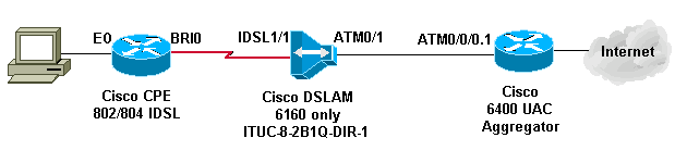
Network Diagram
This document uses this network setup:
Step-by-Step Instructions
In order to configure a router with a BRI interface for IDSL, complete these steps:
-
Add these commands:
isdn leased-line bri [#] [128|144]
!
interface bri [#]
  no shut
!
At this point the line comes up, but not the line protocol (like a serial port).
Do not issue the show isdn status command. It is irrelevant since there is not a D-channel. It sometimes shows that Layer 1 is down when it is not down.
-
Issue a show int bri[#] command and follow the rules of a serial interface in terms of line protocol and line status.
-
Add the PPP or Frame Relay configuration.
This example shows the PPP configuration:
isdn leased-line bri 0 128
!
username b-nrp password 0 cisco

!--- b-nrp is the username assigned to the ISDN router !--- to authenticate with the ISP. !--- cisco is the password assigned to the ISDN router !--- to authenticate with the ISP.

!
!
interface BRI0
 ip address 7.7.7.2 255.255.255.0
 encapsulation ppp
 ppp authentication chap
!
These two examples show Frame Relay configuration. Make sure that you use Internet Engineering Task Force (IETF) encapsulation.
Example 1
!
interface BRI0/0
 ip address 10.0.0.1 255.255.255.0
 no ip directed-broadcast
 encapsulation frame-relay IETF
 fair-queue 64 16 0
 frame-relay map ip 10.0.0.2 300 broadcast IETF
 frame-relay lmi-type ansi
!
Example 2
!
interface BRI0/0
 no ip address
 no ip directed-broadcast
 encapsulation frame-relay IETF
 fair-queue 64 16 0
 frame-relay lmi-type ansi
!
interface BRI0/0.300 point-to-point
 ip address 10.0.0.2 255.255.255.0
 no ip directed-broadcast
 frame-relay interface-dlci 300 IETF
!
Note: Remember that there is no signaling, dialer interface, dialer lists, dialer strings, and no dialer maps. This is a dedicated line like a dedicated T1 serial line. The only difference is that 2B1Q modulation is used instead of V.35, which is used for data service unit/channel service unit (DSU/CSU).
If the line protocol does not come up for PPP, issue these debug commands:
-
debug ppp negotiation
-
debug ppp authentication
-
debug ppp error
Configure the Telco NI2 DSLAM
The NI2 DSLAM configuration assumes a knowledge of a DSL and ATM configuration, that includes PPP over ATM (PPPoA). The IDSL configuration is more in-depth than an asymmetric digital subscriber line (ADSL) or single-line digital subscriber line (SDSL) setup.
In order to use IDSL cards in the DSLAM, Cisco IOS Software Release 12.1(2)DA or later is required.
On the DSLAM, the ADSL and SDSL interfaces are shown in the configuration as ATM interfaces. The Cisco implementations of ADSL and SDSL use ATM. However, IDSL uses HDLC frames in order to transport data. As a result, the interfaces appear as IDSL interfaces in the configuration.
For one IDSL card in a Cisco 6160 DSLAM, the configuration looks like this output:
!
interface IDSL3/1
 no ip address
 no logging event link-status
 no arp frame-relay
!
interface IDSL3/2
 no ip address
 no logging event link-status
 no arp frame-relay
!
interface IDSL3/3
 no ip address

no logging event link-status
 no arp frame-relay
!
interface IDSL3/4
 no ip address
 no logging event link-status
 no arp frame-relay
!
interface IDSL3/5
 no ip address
 no logging event link-status
 no arp frame-relay
!
interface IDSL3/6
 no ip address
 no logging event link-status
 no arp frame-relay
!
interface IDSL3/7
 no ip address
 no logging event link-status
 no arp frame-relay
!
interface IDSL3/8
 no ip address
 no logging event link-status
 no arp frame-relay
!
Note: NI1 DSLAM platforms do not support IDSL and there is no plan to provide this support.
Convert HDLC Frames to ATM Cells
For every IDSL interface there is a pseudo ATM interface. On the hardware, the HDLC frames are converted to ATM cells before they are switched by the NI2 ATM fabric.
For PPP, define a permanent virtual circuit (PVC) that has a destination virtual path identifier (VPI) and virtual channel identifier (VCI). A source VCI/VPI is not required because there is only one connection for PPP.
For Frame Relay, set up sixteen PVCs, which translate into sixteen data-link connection identifiers (DLCIs). The configuration involves the provision of a source DLCI number and a destination VPI/VCI pair.
There are two major steps in a DSL configuration. For the PPP configuration, they are:
-
Set up the IDSL DSL profile.
-
Set up the PVC/SVC under the IDSL interface.
In addition, set up Quality of Service (QoS) for the IDSL link so that the ATM resources that go to the IDSL ports are used properly. Calculate the overhead for ATM framing. This table shows the maximum ATM peak cell rate/sustainable cell rate (PCR/SCR) that you need to configure for the equivalent IDSL bitrate.
| IDSL Bitrate Configured (kbps) | Max ATM PCR/SCR (kbps) |
|---|---|
| 56 | 71 |
| 64 | 81 |
| 128 | 163 |
| 144 | 183 |
These PPP options are available for the IDSL profile:
idsl bitrate [56 | 64 | 128 | 144]
idsl encapsulation [cisco-ppp | llc-ppp | mux-ppp ]
The bitrate must match the bitrate of the CPE. The encapsulation designates the type of PPPoA encapsulation that terminates at the aggregator.
This is the syntax used to create a PVC that connects to the IDSL PPP termination:
ppp pvc interface atm 0/x [VPI] [VCI]
There is no input PVC because the PPP link has only one connection. ATM 0/x is the ATM pipe out of the DSLAM to the aggregator.
In order to set up QoS parameters, use this global command. Use the PCR/SCR table for pcr and scr10 values.
atm connection-traffic-table-row index [row #] vbr-nrt pcr [#] scr10 [#]
In order to apply these values to the IDSL PVC, change ppp pvc interface atm 0/x [VPI] [VCI] to ppp pvc interface atm 0/x [VPI] [VCI] rx-cttr [row #] tx-cttr [row #] .
A PPP IDSL configuration that uses 128 Kbps and llc-ppp encapsulation to the aggregator is:
atm connection-traffic-table-row index 128 vbr-nrt
pcr 163 scr10 163
!
dsl-profile idsl1
 idsl encapsulation llc-ppp

!--- 128 kbps is the default.

!
!
interface IDSL3/1
 dsl profile idsl1
 ppp pvc interface ATM0/1 3 300 rx-cttr 128 tx-cttr 128
!
Configure the Aggregator for PPP Encapsulation
If the DSLAM is configured for encapsulation llc-ppp under the IDSL profile (or nothing is set for encapsulation because this is default), then the aggregator needs to have this configuration:
!
interface ATM0/0/0.300 point-to-point
 no ip directed-broadcast
 pvc 3/300
  encapsulation aal5snap
  protocol ppp Virtual-Template10
 !
!
If the DSLAM is configured for encapsulation cisco-ppp, change the configuration to:
!
interface ATM0/0/0.300 point-to-point
 no ip directed-broadcast
 pvc 3/300
  encapsulation aal5ciscoppp Virtual-Template10
 !
!
If the DSLAM is configured for IDSL encapsulation mux-ppp, make sure that the configuration on the aggregator is:
!
interface ATM0/0/0.300 point-to-point
 no ip directed-broadcast
 pvc 3/300
  encapsulation aal5mux ppp Virtual-Template10
 !
!
Configure Frame Relay
For the Frame Relay configuration, the two major steps are the same as in the PPP configuration.
-
Set up the IDSL DSL profile.
-
Set up the PVC/SVC under the IDSL interface.
For the QoS on the Frame Relay link, no special conversion is necessary. Set the maximum rate in the connection-table-row so that it matches the bandwidth defined on the CPE.
For the IDSL profile, these are the options for Frame Relay:
idsl bitrate [56 | 64 | 128 | 144]
idsl frame-relay ?
     bc-default   Default Bc in bytes
     lmi-n392dce  LMI error threshold
     lmi-n393dce  set LMI monitored event count
     lmi-t392dce  set DCE polling verification timer
     lmi-type     Use CISCO-ANSI-CCITT type LMI
     upc-intent   UPC to use on Soft-VCs/PVCs
In order to enable Frame Relay encapsulation, you also must add the idsl encapsulation frame-relay command.
This syntax creates a PVC that connects to the IDSL Frame Relay termination:
frame-relay pvc [DLCI] service translation interface atm0/1 [VPI] [VCI]
There also is a transparent parameter that is not discussed in this document. The translation keyword translates the Frame Relay DLCI defined into the ATM PVC defined. The ATM PVC is an AAL5SNAP PVC.
In order to set up the QoS parameters, use this global command:
frame-relay connection-traffic-table-row index [row #] [CIR] [Burst] [PIR] vbr-rt
Usually, CIR=PIR equals the bandwidth defined in the IDSL profile for the link. The burst rate is usually at the maximum of 32,768 bps.
In order to apply these values to the IDSL PVC, change frame-relay pvc [DLCI] service translation interface atm0/1 [VPI] [VCI] to frame-relay pvc [DLCI] rx-cttr [Row #] tx-cttr [Row #] service translation interface atm0/1 [VPI] [VCI].
A Frame Relay IDSL configuration that uses 128 Kbps with lmi-type ANSI is:
!
dsl-profile idslframe
 idsl encapsulation frame-relay
 idsl frame-relay lmi-type ansi
!
frame-relay connection-traffic-table-row index 128 128000 32768
128000 vbr-rt
!
!
interface IDSL2/2
 no ip address
 dsl profile idslframe
 no arp frame-relay
 frame-relay pvc 300 rx-cttr 128 tx-cttr 128 service translation
interface  ATM0/1 3 300
!
Configure the Aggregator for Frame Relay Encapsulation
For Frame Relay encapsulation on the CPE side, the DSLAM converts the Frame Relay PVC to an ATM PVC. The ATM PVC is encapsulated in AAL5SNAP.
For a routed Frame Relay PVC:
!
interface ATM0/0/0.300 point-to-point
 ip address 10.0.0.1 255.255.255.0
 pvc 3/300
  encapsulation aal5snap
  protocol ip (inarp) broadcast
 !
!
Similar to other cards that are inserted into the DSLAM chasis, the IDSL card probably needs to be manually designated in the NI2 configuration.
DSLAM(config)#slot 2 ituc-1-8IDSL
After the IDSL card is inserted, issue a show oir status command in order to show the status of the code downloaded to the card.
DSLAM#show oir status 2
Slot 2: timer stopped delay 100
last heard 30348 ms ago, last sent 30348 ms ago
Slot 2: loading. . .         current offset 0x1CFD1, done at 0xBF858
This log output is seen.
00:04:20: %SLOT-3-MODULE_DETECTED: CLEAR INFO Slot 2 Module was
detected
00:04:45: %SLOT-3-MODULE_MISSING: CLEAR MAJOR Slot 2 Provisioned
slot is empty
00:04:45: %SLOT-3-MODULE_DETECTED: ASSERT INFO Slot 2 Module was
detected
00:04:48: %LINK-3-UPDOWN: Interface IDSL2/1 to IDSL2/8, changed
state to down

DSLAM#show hardware
Chassis Type: C6160
Slot 1 : STUC-4-2B1Q-DIR-1                      Slot 18: EMPTY
Slot 2 : ITUC-1-8IDSL                           Slot 19: EMPTY
Slot 3 : EMPTY                                  Slot 20: EMPTY
Slot 4 : EMPTY                                  Slot 21: EMPTY
Slot 5 : EMPTY                                  Slot 22: EMPTY
Slot 6 : EMPTY                                  Slot 23: EMPTY
Slot 7 : EMPTY                                  Slot 24: EMPTY
Slot 8 : EMPTY                                  Slot 25: EMPTY
Slot 9 : EMPTY                                  Slot 26: EMPTY
Slot 10: NI-2-155SM-DS3                         Slot 27: EMPTY
Slot 11: EMPTY                                  Slot 28: EMPTY
Slot 12: EMPTY                                  Slot 29: EMPTY
Slot 13: EMPTY                                  Slot 30: EMPTY
Slot 14: EMPTY                                  Slot 31: EMPTY
Slot 15: EMPTY                                  Slot 32: EMPTY
Slot 16: EMPTY                                  Slot 33: EMPTY
Slot 17: EMPTY                                  Slot 34: EMPTY

Fan Module:  Present
Power Supply Module 1:  Present   2:  Not Present
Troubleshoot IDSL PPP Connections
This section provides the information you can use to troubleshoot your configuration.
Troubleshoot Commands
Certain show commands are supported by the Output Interpreter Tool (registered customers only) , which allows you to view an analysis of show command output.
Note: Before you issue debug commands, refer to Important Information on Debug Commands.
-
debug ppp negotiation—Monitors PPP negotiation events.
-
debug ppp authentication—Determines if a client passes authentication.
-
show dsl interface idsl 2/2—Displays IDSL and connection statistics.
-
show atm vc interface—Displays the pseudo ATM interface behind the IDSL interface.
-
show users—Displays information about active users.
In order to troubleshoot an IDSL PPP connection, issue the debug ppp negotiation and debug ppp authentication commands. For an active connection, this is the output of a show users command
Router#show users

    Line       User      Host(s)             Idle       Location
 *  0 con 0              idle                00:00:00

   Interface   User      Mode                Idle Peer Address
   BR0/0         b-nrp   Sync PPP        00:00:03 10.0.0.2
On the DSLAM, these commands show IDSL statistics and connection statistics.
DSLAM#show dsl interface idsl 2/2
Port Status:
 Subscriber Name:         Circuit ID:
 IOS admin: UP     oper: UP    Card status: ITUC-1-8IDSL
 Last Change: 00 days, 00 hrs, 07 min, 13 sec  No. of changes: 1

 Loopback: none
 Firmware version: 961170635
 BERT has not been executed on this interface
Configured:
 Profile Name:   default
 Alarms Enabled: NO
 IDSL profile parameters
      Bitrate:             128 kbit/sec
      Encapsulation:       llc-ppp
      Frame Relay parameters:
         UPC intent:       pass
         Bc default:       32768 bytes
         LMI type:         cisco
         lmi-n392dce:      2 events
         lmi-n393dce:      2 events
         lmi-t392dce:      15 seconds

Performance Statistics:
 Physical layer
  Coding violations        : 0
  Errored seconds          : 0
  Severely errored seconds : 0
 Physical layer (far end)
  Coding violations        : 0
  Errored seconds          : 0
  Severely errored seconds : 0
 HDLC layer
  Coding violations        : 0
  Aborts                   : 0
  Aligns                   : 0
  Shorts                   : 5
  Longs                    : 0
  Discards                 : 42
Alarm Status: NONE
Note that each IDSL interface has an associated pseudo ATM interface behind it.
DSLAM#show atm vc interface atm-p 2/2
Interface     VPI   VCI   Type   X-Interface  X-VPI  X-VCI   Encap
Status
ATM-P2/2      0    37     PVC     ATM0/1        3      300     UP


DSLAM#show atm vc interface atm-p 2/2 0 37

Interface: ATM-P2/2, Type: ATM-PSEUDO
VPI = 0  VCI = 37
Status: UP
Time-since-last-status-change: 00:02:24
Connection-type: PVC
Cast-type: point-to-point
Packet-discard-option: disabled
Usage-Parameter-Control (UPC): pass
Number of OAM-configured connections: 0
OAM-configuration: disabled
OAM-states:  Not-applicable
Cross-connect-interface: ATM0/1, Type: suni_dual
Cross-connect-VPI = 3
Cross-connect-VCI = 300
Cross-connect-UPC: pass
Cross-connect OAM-configuration: disabled
Cross-connect OAM-state:  Not-applicable
Rx cells: 27, Tx cells: 0
Rx connection-traffic-table-index: 128
Rx service-category: VBR-NRT (Non-Realtime Variable Bit Rate)
Rx pcr-clp01: 163
Rx scr-clp01: 163
Rx mcr-clp01: none
Rx      cdvt: none
Rx       mbs: 1024 (from default for interface)
Tx connection-traffic-table-index: 128
Tx service-category: VBR-NRT (Non-Realtime Variable Bit Rate)
Tx pcr-clp01: 163
Tx scr-clp01: 163
Tx mcr-clp01: none
Tx      cdvt: none
Tx       mbs: none
You also can look at the PVC from the other side (from the aggregator toward the CPE).
DSLAM#show atm vc interface atm 0/1 3 300

Interface: ATM0/1, Type: suni_dual
VPI = 3  VCI = 300
Status: UP
Time-since-last-status-change: 00:03:20
Connection-type: PVC
Cast-type: point-to-point
Packet-discard-option: disabled
Usage-Parameter-Control (UPC): pass
Number of OAM-configured connections: 0
OAM-configuration: disabled
OAM-states:  Not-applicable
Cross-connect-interface: ATM-P2/2, Type: ATM-PSEUDO
Cross-connect-VPI = 0
Cross-connect-VCI = 37
Cross-connect-UPC: pass
Cross-connect OAM-configuration: disabled
Cross-connect OAM-state:  Not-applicable
Rx cells: 0, Tx cells: 68
Rx connection-traffic-table-index: 128
Rx service-category: VBR-NRT (Non-Realtime Variable Bit Rate)
Rx pcr-clp01: 163
Rx scr-clp01: 163
Rx mcr-clp01: none
Rx      cdvt: none
Rx       mbs: 1024 (from default
for interface)
Tx connection-traffic-table-index: 128
Tx service-category: VBR-NRT (Non-Realtime Variable Bit Rate)
Tx pcr-clp01: 163
Tx scr-clp01: 163
Tx mcr-clp01: none
Tx      cdvt: none
Tx       mbs: none
Troubleshoot IDSL Frame Relay Connections
This section provides the information you can use in order to troubleshoot your configuration.
Troubleshoot Commands
Certain show commands are supported by the Output Interpreter Tool (registered customers only) , which allows you to view an analysis of show command output.
Note: Before you issue debug commands, refer to Important Information on Debug Commands.
-
show frame lmi—Displays statistics about the Local Management Interface (LMI).
-
debug frame lmi—Determines if LMI packets are properly sent and received.
-
show frame-relay pvc—Displays PVC statistics for Frame Relay interfaces.
-
show frame map—Displays the current map entries and information about the connections.
-
show frame-relay interface resource—Displays QoS parameters.
-
show interface idsl—Displays Frame Relay statistics.
-
show atm vc interface—Displays the pseudo ATM interface behind the IDSL interface.
In order to troubleshoot an IDSL BRI port connection, use the same commands used to troubleshoot a serial port.
Router#show frame lmi

!--- Check for status messages received and Enq. sent.


LMI Statistics for interface BRI0/0 (Frame Relay DTE) LMI TYPE = CISCO

  Invalid Unnumbered info 0             Invalid Prot Disc 0
  Invalid dummy Call Ref 0              Invalid Msg Type 0
  Invalid Status Message 0              Invalid Lock Shift 0
  Invalid Information ID 0              Invalid Report IE Len 0
  Invalid Report Request 0              Invalid Keep IE Len 0
  Num Status Enq. Sent 71               Num Status msgs Rcvd 0
  Num Update Status Rcvd 0              Num Status Timeouts 70
Timeouts mean that there is no communication from the NI2 switch.
In order to debug, issue the debug frame lmi command in the same manner as it is used for a serial interface. You also can issue the show frame-relay pvc and show frame map commands.
Router#show frame lmi

LMI Statistics for interface BRI0/0 (Frame Relay DTE) LMI TYPE = ANSI

  Invalid Unnumbered info 0             Invalid Prot Disc 0
  Invalid dummy Call Ref 0              Invalid Msg Type 0
  Invalid Status Message 0              Invalid Lock Shift 0
  Invalid Information ID 0              Invalid Report IE Len 0
  Invalid Report Request 0              Invalid Keep IE Len 0
  Num Status Enq. Sent 17               Num Status msgs Rcvd 18
  Num Update Status Rcvd 0              Num Status Timeouts 0

Router#show frame-relay pvc

PVC Statistics for interface BRI0/0 (Frame Relay DTE)

             Active      Inactive      Deleted      Static

  Local         1            0             0            0
  Switched      0            0             0            0
  Unused        0            0             0            0

DLCI = 300, DLCI USAGE = LOCAL, PVC STATUS = ACTIVE, INTERFACE = BRI0/0

  input pkts 0             output pkts 0            in bytes 0
  out bytes 0              dropped pkts 0           in FECN pkts 0
  in BECN pkts 0           out FECN pkts 0          out BECN pkts 0
  in DE pkts 0             out DE pkts 0
  out bcast pkts 0         out bcast bytes 0
  pvc create time 00:02:30, last time pvc status changed 00:02:30


Router#show frame map
BRI0/0 (up): ip 10.0.0.2 dlci 300(0x12C,0x48C0), static,
              broadcast,
              IETF, status defined, active
On the DSLAM side, you also can issue a show frame lmi command.
DSLAM#show frame-relay lmi interface idsl2/2

LMI Statistics for interface IDSL2/2 (Frame Relay DCE) LMI TYPE = ANSI
  Invalid Unnumbered info 0             Invalid Prot Disc 0
  Invalid dummy Call Ref 0              Invalid Msg Type 0
  Invalid Status Message 0              Invalid Lock Shift 0
  Invalid Information ID 0              Invalid Report IE Len 0
  Invalid Report Request 0              Invalid Keep IE Len 0
  Num Status Enq. Rcvd 2                Num Status msgs Sent 2
  Num Update Status Sent 0              Num St Enq. Timeouts 0
In order to see QoS parameters, issue the show frame-relay interface resource command.
DSLAM#show frame-relay interface resource idSL 2/1
Encapsulation: FRAME-RELAY
Resource Management state:
 Available bit rates (in bps):
    128000 vbr-nrt RX, 128000 vbr-nrt TX
    128000 vbr-rt RX,  128000 vbr-rt TX
    128000 ubr RX,
    128000 ubr TX
 Allocated bit rates (in bps):
    0 vbr-nrt RX, 0 vbr-nrt TX
    0 vbr-rt RX,  0 vbr-rt TX
    0 ubr RX,     0 ubr TX
When the interface is configured for Frame Relay mode, issue a show interface idsl command in order to show Frame Relay statistics.
DSLAM#show interface idsl2/2
IDSL2/2 is up, line protocol is up
  Hardware is idsl
  MTU 1500 bytes, BW 128 Kbit, DLY 0 usec,
     reliability 255/255, txload 1/255, rxload 1/255
  Encapsulation FRAME-RELAY IETF, loopback not set
  Keepalive set (10 sec)
  LMI enq sent  0, LMI stat recvd 0, LMI upd recvd 0
  LMI enq recvd 8, LMI stat sent  8, LMI upd sent  0, DCE LMI up
  LMI DLCI 0  LMI type is ANSI Annex D  frame relay DCE
  Broadcast queue 0/64, broadcasts sent/dropped 0/0, interface broadcasts 0
  Last input 00:00:03, output 00:00:03, output hang never
  Last clearing of "show interface" counters 00:01:20
  Queueing strategy: fifo
  Output queue 0/40, 0 drops; input queue 0/75, 0 drops
  5 minute input rate 0 bits/sec, 0 packets/sec
  5 minute output rate 0 bits/sec, 0 packets/sec
     8 packets input, 112 bytes, 0 no buffer
     Received 0 broadcasts, 0 runts, 0 giants, 0 throttles
     0 input errors, 0 CRC, 0 frame, 0 overrun, 0 ignored, 0 abort
     8 packets output, 117 bytes, 0 underruns
     0 output errors, 0 collisions, 0 interface resets
     0 output buffer failures, 0 output buffers swapped out
     0 carrier transitions


DSLAM#show dsl interface idsl 2/2
Port Status:
 Subscriber Name:           Circuit ID:
 IOS admin: UP      oper: UP    Card status: ITUC-1-8IDSL
 Last Change: 00 days, 00 hrs, 06 min, 09 sec  No. of changes: 64

 Loopback: none

 Firmware version: 961170635

 BERT has not been executed on this interface

Configured:
 Profile Name:   idslframe
 Alarms Enabled: NO

 IDSL profile parameters
      Bitrate:            128 kbit/sec
      Encapsulation:      frame-relay
      Frame Relay parameters:
         UPC intent:      pass
         Bc default:      32768 bytes
         LMI type:        ansi
         lmi-n392dce:     2 events
         lmi-n393dce:     2 events
         lmi-t392dce:     15 seconds

Performance Statistics:
 Physical layer
  Coding violations        : 0
  Errored seconds          : 0
  Severely errored seconds : 0
 Physical layer (far end)
  Coding violations        : 0
  Errored seconds          : 0
  Severely errored seconds : 0
 HDLC layer
  Coding violations        : 0
  Aborts                   : 0
  Aligns                   : 0
  Shorts                   : 0
  Longs                    : 0
  Discards                 : 0

Alarm Status: NONE


DSLAM#show atm vc interface atm-p 2/2
Interface     VPI   VCI   Type   X-Interface  X-VPI X-VCI   Encap
Status
ATM-P2/2      0    37     PVC     ATM0/1        3     300    UP


DSLAM#show atm vc interface atm-p 2/2 0 37

Interface: ATM-P2/2, Type: ATM-PSEUDO
VPI = 0  VCI = 37
Status: UP
Time-since-last-status-change: 00:06:59
Connection-type: PVC
Cast-type: point-to-point
Packet-discard-option: disabled
Usage-Parameter-Control (UPC): pass
Number of OAM-configured connections: 2
OAM-configuration: Ais-on
OAM-states:  OAM-Up
OAM-Loopback-Tx-Interval: 5
Cross-connect-interface: ATM0/1, Type: suni_dual
Cross-connect-VPI = 3
Cross-connect-VCI = 300
Cross-connect-UPC: pass
Cross-connect OAM-configuration: Ais-on
Cross-connect OAM-state:  OAM-Up
OAM-Loopback-Tx-Interval: 5
Rx cells: 0, Tx cells: 0
Rx connection-traffic-table-index: 100
Rx service-category: VBR-NRT (Non-Realtime Variable Bit Rate)
Rx pcr-clp01: 106
Rx scr-clp0 : 106
Rx mcr-clp01: none
Rx      cdvt: none
Rx       mbs: 50
Tx connection-traffic-table-index: 100
Tx service-category: VBR-NRT (Non-Realtime Variable Bit Rate)
Tx pcr-clp01: 106
Tx scr-clp0 : 106
Tx mcr-clp01: none
Tx      cdvt: none
Tx       mbs: 50
Issues and Bugs
PPP over Frame Relay is not supported for the Cisco 800 series for IDSL.
If you wish to use a Cisco router for an IDSL application and the router runs a Cisco IOS Software Release earlier than 12.1, you must configure the ISDN switch type. Refer to Configuring Cisco Routers for Use with IDSL for more information.
If you do not configure the ISDN switch type, the BRI interface of the router probably does not come back up after the IDSL line goes down and back up. In order to prevent this problem, issue the isdn switch-type basic-ni command while in global configuration mode.
This problem does not occur if the Cisco router runs Cisco IOS Software Release 12.1 or later.
Related Information
 Feedback
Contact Cisco
- Open a Support Case

- (Requires a Cisco Service Contract)