Rubrik CDM on Cisco UCS C-Series Rack Systems
Available Languages
Bias-Free Language
The documentation set for this product strives to use bias-free language. For the purposes of this documentation set, bias-free is defined as language that does not imply discrimination based on age, disability, gender, racial identity, ethnic identity, sexual orientation, socioeconomic status, and intersectionality. Exceptions may be present in the documentation due to language that is hardcoded in the user interfaces of the product software, language used based on RFP documentation, or language that is used by a referenced third-party product. Learn more about how Cisco is using Inclusive Language.
- US/Canada 800-553-2447
- Worldwide Support Phone Numbers
- All Tools
 Feedback
 Feedback
In partnership with:

![]()
About the Cisco Validated Design Program
The Cisco Validated Design (CVD) program consists of systems and solutions designed, tested, and documented to facilitate faster, more reliable, and more predictable customer deployments. For more information, go to: http://www.cisco.com/go/designzone.
Digital transformation has brought significant benefits to organizations, including increased agility and flexibility, but it has also led to a rise in cyber attack vectors. 66 percent of organizations were hit with ransomware within the last year, according to a 2022 Sophos survey. The widespread adoption of cloud services and Software-as-a-Service (SaaS) applications has expanded the attack surface, making it more challenging to manage and secure data. Additionally, the increased use of mobile devices and remote work have made it easier for cybercriminals to launch attacks from anywhere, at any time.
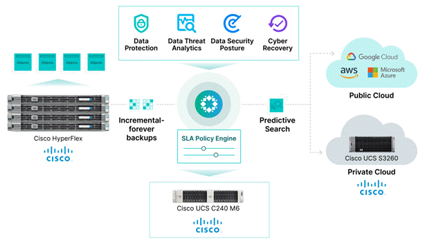
Rubrik Security Cloud is the leading data security platform built upon a unique backup architecture that secures data. Rubrik is designed with zero trust principles to incorporate a logical air gap, secure protocols, native immutability, encryption, and access controls. The principal economic benefit of Rubrik is reduced costs associated with combating cyber threats. Data Protection safeguards data with secure backups. Data Threat Analytics makes it easy to monitor data risk and investigate threats faster. Data Security Posture helps to proactively reduce data exposure risk. Cyber Recovery helps restore business operations faster.
Rubrik Security Cloud on Cisco UCS C-Series systems, managed through Cisco Intersight provides an appliance-like deployment model. Business resilience, agility, flexibility, and orchestration of resources at scale across the edge, public, and private cloud environments are a key value differentiators of this joint solution.
This Cisco Validated Design and Deployment Guide provides prescriptive guidance for the design, setup, configuration, and ongoing use of the Rubrik Security Cloud on the Cisco UCS C-Series Rack System. Together, Cisco and Rubrik deliver the unified computing and Zero Trust Data Security capabilities you need to meet the demands for increased development agility and management of distributed environments, while ensuring your data is resilient against cyber-attacks, malicious insiders, and operational disruptions.
This chapter contains the following:
● Audience
With Rubrik, organizations can be confident that their critical data is safe from deletion, compromise, or encryption. This is because air-gapped, immutable, access-controlled backups enable organizations to withstand cyberattacks, malicious insiders, and operational disruptions. Data is stored in an immutable format and cannot be read, modified, or deleted. Additionally, data is encrypted in-flight and at rest, and backup data is stored in a purpose-built append-only file system.
Lastly, backed up data is logically air-gapped so it’s offline and not accessible through standard network protocols. System interfaces are secure, role-based, least privileged, and protected by multifactor authentication (MFA) to further reduce the risk of intrusion.
Data Resilience services include:
● Enterprise Data Protection – to keep your enterprise data safe from attacks or disasters.
● Cloud Data Protection – to ensure your cloud data is secure from compromise.
● SaaS Data Protection – to secure your SaaS application data with automated protection.
● Unstructured Data Protection – to protect, monitor, and rapidly recover unstructured data at petabyte-scale.
The Rubrik CDM joint solution with Cisco UCS, provides customers with a solution that is easy to deploy, manage and expand as per the growing demands of data protection workloads. Besides the best in class cyber security Rubrik solution, the security of the Cisco UCS platform starts with Cisco’s value chain or supply chain security, through a layered approach to the manufacturing facilities – all to ensure that there’s no tampering happening while the platform is being built. Cisco UCS products are designed and tested to Cisco’s rigorous security framework, using the latest technologies for prevention, and following comprehensive cybersecurity programs.
The Cisco Intersight platform uses a layered security architecture that builds on industry-standard security technologies. It also encrypts data, complies with strict Cisco security and data handling standards, and separates management and IT production network traffic for additional isolation. As a result, you can have confidence that your cloud-based systems management platform offers the strong security you require.
The intended audience for this document includes, but is not limited to, sales engineers, field consultants, professional services, IT managers, IT engineers, partners, and customers who are interested in learning about and deploying a secure, and scalable data protection solution for backup and recovery of workloads.
This document describes the design, configuration, deployment steps for the Rubrik CDM on Cisco UCS C-Series platform managed through Cisco Intersight.
This solution provides a reference architecture and validated deployment procedure for the Rubrik CDM on Cisco UCS C-Series platform managed through Cisco Intersight.
The key elements of this solution are as follows:
● Cisco Intersight—is a cloud operations platform that delivers intelligent visualization, optimization, and orchestration for applications and infrastructure across public cloud and on-premises environments. Cisco Intersight provides an essential control point for customers to get more value from hybrid IT investments by simplifying operations across on-prem and their public clouds, continuously optimizing their multi cloud environments and accelerating service delivery to address business needs.
● Cisco UCS C-Series platform— The Cisco UCS C240 M6 Rack Server is a 2-socket, 2-Rack-Unit (2RU) rack server offering industry-leading performance and expandability. It supports a wide range of storage and I/O-intensive infrastructure workloads, from big data and analytics to collaboration. Cisco UCS C-Series M6 Rack Servers can be deployed as standalone servers or as part of a Cisco Unified Computing System (Cisco UCS) managed environment, and now with Cisco Intersight is able to take advantage of Cisco’s standards-based unified computing innovations that help reduce customers’ Total Cost of Ownership (TCO) and increase their business agility.
● Rubrik Security Cloud — Rubrik Security Cloud gives organizations a single place to secure their data wherever it lives—across enterprise, cloud, and SaaS applications.
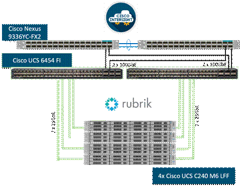
Figure 1 illustrates the deployment overview of the Rubrik Security Cloud on Cisco UCS.
This chapter contains the following:
● Cisco UCS C240 M6 Large Form Factor (LFF) Rack Server
As applications and data become more distributed from core data center and edge locations to public clouds, a centralized management platform is essential. IT agility will be a struggle without a consolidated view of the infrastructure resources and centralized operations. Cisco Intersight provides a cloud-hosted, management and analytics platform for all Cisco HyperFlex, Cisco UCS, and other supported third-party infrastructure deployed across the globe. It provides an efficient way of deploying, managing, and upgrading infrastructure in the data center, ROBO, edge, and co-location environments.
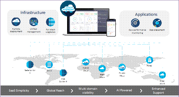
Cisco Intersight provides:
● No Impact Transition: Embedded connector (Cisco HyperFlex, Cisco UCS) will allow customers to start consuming benefits without forklift upgrade.
● SaaS/Subscription Model: SaaS model provides for centralized, cloud-scale management and operations across hundreds of sites around the globe without the administrative overhead of managing the platform.
● Enhanced Support Experience: A hosted platform allows Cisco to address issues platform-wide with the experience extending into TAC supported platforms.
● Unified Management: Single pane of glass, consistent operations model, and experience for managing all systems and solutions.
● Programmability: End to end programmability with native API, SDK’s and popular DevOps toolsets will enable customers to deploy and manage the infrastructure quickly and easily.
● Single point of automation: Automation using Ansible, Terraform and other tools can be done through Intersight for all systems it manages.
● Recommendation Engine: Our approach of visibility, insight and action powered by machine intelligence and analytics provide real-time recommendations with agility and scale. Embedded recommendation platform with insights sourced from across Cisco install base and tailored to each customer.
In this solution, Cisco Intersight provides a single global SaaS platform allowing management of Cisco C-Series Rack servers running the Rubrik CDM deployed across multiple data centers, edge, or remote sites. The life cycle management capabilities that Cisco Intersight offers allows easier Day 0 deployment, continuous monitoring of infrastructure, proactive RMAs, firmware upgrades and easier expansion of Rubrik CDM Clusters.
For more information, go to the Cisco Intersight product page on cisco.com.
Cisco Intersight Virtual Appliance and Private Virtual Appliance
In addition to the SaaS deployment model running on Intersight.com, you can purchase on-premises options separately. The Cisco Intersight virtual appliance and Cisco Intersight private virtual appliance are available for organizations that have additional data locality or security requirements for managing systems. The Cisco Intersight virtual appliance delivers the management features of the Cisco Intersight platform in an easy-to-deploy VMware Open Virtualization Appliance (OVA) or Microsoft Hyper-V Server virtual machine that allows you to control the system details that leave your premises. The Cisco Intersight private virtual appliance is provided in a form factor designed specifically for users who operate in disconnected (air gap) environments. The private virtual appliance requires no connection to public networks or to Cisco network.
Cisco Intersight Assist helps you add endpoint devices to the Cisco Intersight platform. A datacenter could have multiple devices that do not connect directly with the platform. Any device that the Cisco Intersight platform supports but does not connect with directly must have a connection mechanism, and Cisco Intersight Assist provides it. In FlashStack, VMware vCenter and Pure Storage FlashArray connect to the Intersight platform with the help of the Cisco Intersight Assist virtual machine.
Cisco Intersight Assist is available within the Cisco Intersight virtual appliance, which is distributed as a deployable virtual machine contained within an OVA file format. Later sections in this paper have more details about the Cisco Intersight Assist virtual-machine deployment configuration.
The Cisco Intersight platform uses a subscription-based license with multiple tiers. You can purchase a subscription duration of 1, 3, or 5 years and choose the required Cisco UCS server volume tier for the selected subscription duration. Each Cisco endpoint automatically includes a Cisco Intersight Base license at no additional cost when you access the Cisco Intersight portal and claim a device. You can purchase any of the following higher-tier Cisco Intersight licenses using the Cisco ordering tool:
● Cisco Intersight Essentials: Essentials includes all the functions of the Base license plus additional features, including Cisco UCS Central software and Cisco Integrated Management Controller (IMC) supervisor entitlement, policy-based configuration with server profiles, firmware management, and evaluation of compatibility with the Cisco Hardware Compatibility List (HCL).
● Cisco Intersight Advantage: Advantage offers all the features and functions of the Base and Essentials tiers. It also includes storage widgets and cross-domain inventory correlation across compute, storage, and virtual environments (VMware ESXi). OS installation for supported Cisco UCS platforms is also included.
Servers in the Cisco Intersight managed mode require at least the Essentials license. For more information about the features provided in the various licensing tiers, see: https://www.intersight.com/help/saas/getting_started/licensing_requirements
Cisco UCS C240 M6 Large Form Factor (LFF) Rack Server
The Cisco UCS C240 M6 Rack Server is a 2-socket, 2-Rack-Unit (2RU) rack server offering industry-leading performance and expandability. It supports a wide range of storage and I/O-intensive infrastructure workloads, from big data and analytics to collaboration. Cisco UCS C-Series M6 Rack Servers can be deployed as standalone servers or as part of a Cisco Unified Computing System (Cisco UCS) managed environment, and now with Cisco Intersight is able to take advantage of Cisco’s standards-based unified computing innovations that help reduce customers’ Total Cost of Ownership (TCO) and increase their business agility.
In response to ever-increasing computing and data-intensive real-time workloads, the enterprise-class Cisco UCS C240 M6 server extends the capabilities of the Cisco UCS portfolio in a 2RU form factor. It incorporates 3rd Generation Intel Xeon Scalable processors, supporting up to 40 cores per socket and 33 percent more memory versus the previous generation.
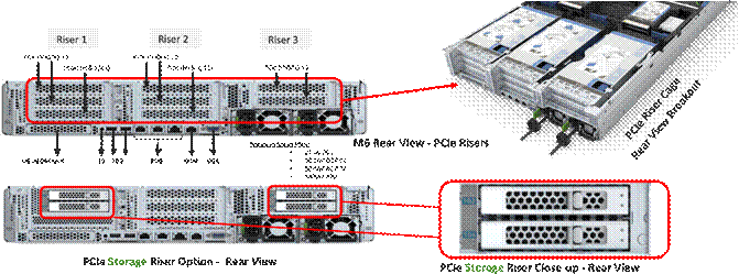
The Cisco UCS C240 M6 rack server brings many new innovations to the Cisco UCS rack server portfolio. With the introduction of PCIe Gen 4.0 expansion slots for high-speed I/O, DDR4 memory bus, and expanded storage capabilities, the server delivers significant performance and efficiency gains that will improve your application performance. Its features including the following:
● Supports the third-generation Intel Xeon Scalable CPU, with up to 40 cores per socket
● Up to 32 DDR4 DIMMs for improved performance, including higher density DDR4 DIMMs (16 DIMMs per socket)
● 16x DDR4 DIMMs + 16x Intel Optane persistent memory modules for up to 12 TB of memory
● Up to 8 PCIe Gen 4.0 expansion slots plus a modular LAN-on-motherboard (mLOM) slot
● Support for Cisco UCS VIC 1400 Series adapters as well as third-party options
● 16 LFF drives with options 4 rear SFF (SAS/SATA/NVMe) disk drives
● Support for a 12-Gbps SAS modular RAID controller in a dedicated slot, leaving the remaining PCIe Gen 4.0 expansion slots available for other expansion cards
● M.2 boot options
● Up to 960 GB with optional hardware RAID
● Up to five GPUs supported
● Modular LAN-on-motherboard (mLOM) slot that can be used to install a Cisco UCS Virtual Interface Card (VIC) without consuming a PCIe slot, supporting quad port 10/40 Gbps or dual port 40/100 Gbps network connectivity
● Dual embedded Intel x550 10GBASE-T LAN-on-motherboard (LOM) ports
● Modular M.2 SATA SSDs for boot
For more details and specification, go to: https://www.cisco.com/c/dam/en/us/products/collateral/servers-unified-computing/ucs-c-series-rack-servers/c240m6-lff-specsheet.pdf

Cisco UCS C240 M6 Rack Server support the following Cisco MLOM VICs and PCIe VICs:
● Cisco UCS VIC 1467 quad port 10/25G SFP28 mLOM
● Cisco UCS VIC 1477 dual port 40/100G QSFP28 mLOM
● Cisco UCS VIC 15428 quad port 10/25/50G MLOM
● Cisco UCS VIC 15238 dual port 40/100/200G MLOM
● Cisco UCS VIC 15427 Quad Port CNA MLOM with Secure Boot
● Cisco UCS VIC 15237, MLOM, 2x40/100/200G for Rack
● Cisco UCS VIC 1495 Dual Port 40/100G QSFP28 CNA PCIe
● Cisco UCS VIC 1455 quad port 10/25G SFP28 PCIe
● Cisco UCS VIC 15425 Quad Port 10/25/50G CNA PCIE
● Cisco UCS VIC 15235 Dual Port 40/100/200G CNA PCIE
In this configuration with Rubrik CDM, Cisco UCS VIC 1467 quad port 10/25G SFP28 mLOM with deployed on Cisco UCS C240 M6 LFF server.
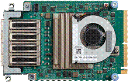
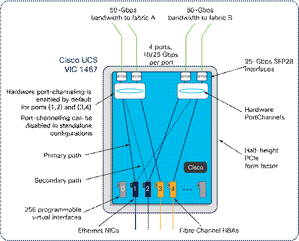
Cisco UCS VIC 1467
The Cisco UCS VIC 1467 is a quad-port Small Form-Factor Pluggable (SFP28) mLOM card designed for Cisco UCS C-Series M6 Rack Servers. The card supports 10/25-Gbps Ethernet or FCoE. The card can present PCIe standards-compliant interfaces to the host, and these can be dynamically configured as either NICs or HBA. For more details, go to: https://www.cisco.com/c/en/us/products/collateral/interfaces-modules/unified-computing-system-adapters/datasheet-c78-741130.html
Cisco UCS 6400 Fabric Interconnects
The Cisco UCS fabric interconnects provide a single point for connectivity and management for the entire Cisco UCS system. Typically deployed as an active-active pair, the fabric interconnects of the system integrate all components into a single, highly available management domain that Cisco UCS Manager or the Cisco Intersight platform manages. Cisco UCS Fabric Interconnects provide a single unified fabric for the system, with low-latency, lossless, cut-through switching that supports LAN, storage-area network (SAN), and management traffic using a single set of cables (Figure 6).
![]()
The Cisco UCS 6454 used in the current design is a 54-port fabric interconnect. This 1RU device includes twenty-eight 10-/25-GE ports, four 1-/10-/25-GE ports, six 40-/100-GE uplink ports, and sixteen unified ports that can support 10-/25-GE or 8-/16-/32-Gbps Fibre Channel, depending on the Small Form-Factor Pluggable (SFP) adapter.
Rubrik Security Cloud
Cyberattacks are increasing in frequency and sophistication. Despite large investments in infrastructure security tools, bad actors are finding their way through to the data. And they know legacy backup tools are vulnerable, so they are increasingly targeting backup data. When a cyberattack takes down data, it takes down businesses. It’s time for a new approach. One that marries the investments made in infrastructure security with data security.
Rubrik is on a mission to secure the world’s data. With Rubrik Security Cloud, you can automatically protect data from cyberattacks, continuously monitor data risks, and quickly recover data and applications across the enterprise, in the cloud, and in SaaS applications.
● Data Protection: Keep Data Readily Available
Ensure data integrity and availability with automated, secure, and access-controlled backups that are designed to withstand cyberattacks, malicious insiders, and operational disruptions.
● Data Threat Analytics: Monitor Data Risk and Investigate Faster
Continuously monitor for threats to data, including ransomware, data destruction, and indicators of compromise.
● Data Security Posture: Proactively Reduce Risk of Data Exposure
Proactively identify and monitor sensitive data exposure and use intelligent insights to mitigate risks to data.
● Cyber Recovery: Restore Business Operations Faster
Quickly return to business as usual within hours or days, not weeks or months. Orchestration and quarantining enable you to contain threats and rapidly recover your apps, files, or objects while avoiding malware reinfection.
Architecture and Design Considerations
This chapter contains the following:
● Deployment Architecture for Cisco UCS C240 with Rubrik
● Network Bond Modes with Rubrik and Fabric Interconnect Managed Systems
Deployment Architecture for Cisco UCS C240 with Rubrik
The Rubrik CDM on Cisco UCS C-Series requires a minimum four (4) nodes. Each Cisco UCS C240 M6 LFF node is equipped with both the compute and storage required to operate the Rubrik CDM. The entire deployment is managed through Cisco Intersight.
Each Cisco UCS C240 M6 LFF node is equipped with:
● 2x Intel 5318N 2.1GHz/150W 24C/36MB DDR4 2667MHz
● 384 GB DDR4 memory
● 2x 240GB M.2 card managed through M.2 RAID controller, for Rubrik operating system
● 1x 1.6 TB NVMe
● 12x 12TB,12G SAS 7.2K RPM LFF HDD (4K) managed through 1x Cisco M6 12G SAS HBA
Figure 7 illustrates the deployment architecture overview of Rubrik on Cisco UCS C-Series nodes.
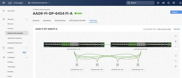
Figure 8 illustrates the cabling diagram for Rubrik on the Cisco UCS C-Series Rack Servers.
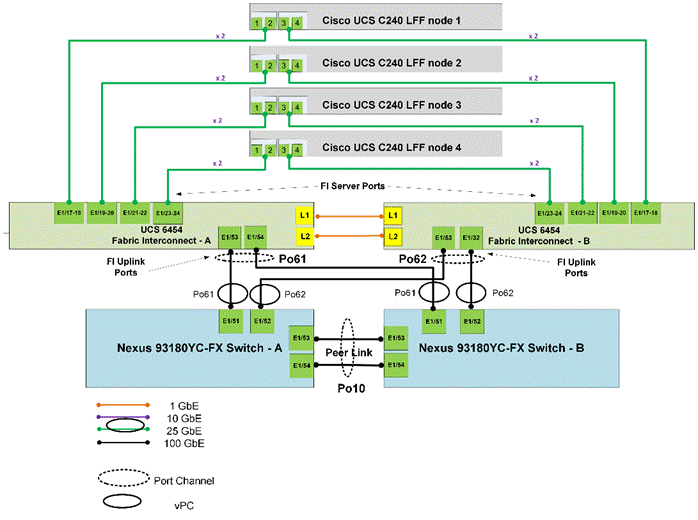
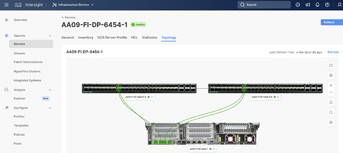
Figure 9 illustrates the cabling topology as captured through Cisco Intersight.
The reference hardware configuration includes:
● Two Cisco Nexus 93360YC-FX Switches in Cisco NX-OS mode provide the switching fabric.
● Two Cisco UCS 6454 Fabric Interconnects (FI) provide the chassis connectivity. One 100 Gigabit Ethernet port from each FI, configured as a Port-Channel, is connected to each Cisco Nexus 93360YC-FX.
● Four (4) Cisco UCS C240 LFF nodes. Each node is equipped with Cisco UCS VIC 1467. The Cisco UCS VIC 1467 is a quad-port Small Form-Factor Pluggable (SFP28) mLOM card designed for Cisco UCS C-Series M6 Rack Servers. Port 1-2 are connected to Server ports on Fabric Interconnect A and Port 3-4 are connected to Server ports on Fabric Interconnect B.
● Cisco Intersight as the SaaS management platform for Cisco UCS Fabric Interconnects and Cisco UCS C-Series Rack Servers.
Note: Do not connect port 1 of the VIC 1467 to Fabric Interconnect A, and then connect port 2 of the VIC 1467 to Fabric Interconnect B. Using ports 1 and 2, each connected to FI A and FI B will lead to discovery and configuration failures.
Note: The Cisco UCS C-Series Servers are connected directly to the Cisco UCS Fabric Interconnects in Direct Connect mode. Internally the Cisco UCS C-Series servers are configured with the PCIe-based system I/O controller for Quad Port 10/25G Cisco VIC 1467. The standard and redundant connection practice is to connect port 1 and port 2 of each server’s VIC card to a numbered port on FI A, and port 3 and port 4 of each server’s VIC card to the same numbered port on FI B. The design also supports connecting just port 1 to FI A and port 3 to FI B. The use of ports 1 and 3 are because ports 1 and 2 form an internal port-channel, as does ports 3 and 4
Network Bond Modes with Rubrik and Fabric Interconnect Managed Systems
All teaming/bonding methods that are switch independent are supported in the Cisco UCS Fabric Interconnect environment. These bonding modes do not require any special configuration on the switch and Cisco UCS side.
The restriction is that any load balancing method used in a switch independent configuration must send traffic for a given source MAC address via a single Cisco UCS Fabric Interconnect other than in a failover event (where the traffic should be sent to the alternate fabric interconnect) and not periodically to redistribute load.
Using other load balancing methods that operate on mechanisms beyond the source MAC address (such as IP address hashing, TCP port hashing, and so on) can cause instability since a MAC address is flapped between UCS Fabric Interconnects. This type of configuration is unsupported.
Switch dependent bonding modes require a port-channel to be configured on the switch side. The fabric interconnect, which is the switch in this case, cannot form a port-channel with the VIC card present in the servers. Furthermore, such bonding modes will also cause MAC flapping on Cisco UCS and upstream switches and is unsupported.
Cisco UCS Servers with Linux Operating System and managed through fabric interconnects, support active-backup (mode 1), balance-tlb (mode 5) and balance-alb (mode 6). The networking mode in the Rubrik operating system (Linux based) deployed on Cisco UCS C-Series managed through a Cisco UCS Fabric Interconnect is validated with bond mode 1 (active-backup). For reference, go to: https://www.cisco.com/c/en/us/support/docs/servers-unified-computing/ucs-b-series-blade-servers/200519-UCS-B-series-Teaming-Bonding-Options-wi.html)
Cisco Intersight uses a subscription-based license with multiple tiers. Each Cisco automatically includes a Cisco Intersight Essential trial license when you access the Cisco Intersight portal and claim a device.
More information about Cisco Intersight Licensing and the features supported in each license can be found here: https://www.cisco.com/site/us/en/products/computing/hybrid-cloud-operations/intersight-infrastructure-service/licensing.html
In this solution, using Cisco Intersight Advantage License Tier enables the following:
● Configuration of Domain and Server Profiles for Rubrik on Cisco UCS C-Series Rack Servers.
● Rubrik OS installation on Cisco UCS C-Series nodes through Cisco Intersight. This requires enabling an NFS/SMB/HTTPS repository which has the certified Rubrik CDM software.
This section details the physical hardware, software revisions, and firmware versions required to install Rubrik CDM Clusters running on Cisco Unified Computing System. A Rubrik on-premises cluster requires a minimum of four physical nodes deployed either on Cisco UCS C-Series Rubrik-certified nodes.
Table 1 lists the required hardware components and disk options for the Rubrik CDM on Cisco UCS C-Series Rack Servers.
Table 1. Cisco UCS C-Series nodes for the Rubrik CDM
| Component |
Hardware |
|
| Fabric Interconnects |
Two (2) Cisco UCS 6454 Fabric Interconnects |
|
| Server Node |
4x Cisco UCS C240 M6 LFF Server Node for Intel Scalable CPUs |
|
| Processors |
Each server node equipped with two Intel 5318N 2.1GHz/150W 24C/36MB |
|
| Memory |
Each server node equipped with 384 GB of total memory using twelve (12) 32GB RDIMM DRx4 3200 (8Gb) |
|
| Disk Controller |
Cisco M6 12G SAS HBA |
|
| Storage (each server node) |
OS Boot |
2x M.2 (240GB) with M.2 HW RAID Controller |
| Caching |
1x 1.6 TB NVMe |
|
|
|
Storage |
12x 12TB 12G SAS 7.2K RPM LFF HDD (4K) |
| Network (Each Server node) |
Cisco UCS VIC 1467 4x25G mLOM |
|
Table 2 lists the software components and the versions required for the Rubrik CDM and Cisco UCS C-Series nodes managed through Cisco UCS Fabric Interconnect in Intersight Managed mode (IMM), as tested, and validated in this document.
| Component |
Version |
| Rubrik CDM |
rubrik_os_8.1.3-p6-25150_iv_3.5.0-138 |
| Cisco Fabric Interconnect 6454 |
4.2 (3h) |
| Cisco UCS C240 M6 LFF servers |
4.2 (3h) |
This chapter contains the following:
● Create Cisco Intersight Account
● Set up Intersight Managed Mode (IMM)
● Manual Set up Server Template
● Install Rubrik CDM on Cisco UCS C-Series Nodes
● Configure Rubrik CDM Cluster
This chapter describes the solution deployment for Rubrik CDM on Cisco UCS C-Series Rack Servers in Intersight Managed Mode (IMM), with step-by-step procedures for implementing and managing the solution.
Prior to beginning the installation activities, complete the following necessary tasks and gather the required information.
IP addresses for the Rubrik CDM on Cisco UCS, need to be allocated from the appropriate subnets and VLANs to be used. IP addresses that are used by the system are comprised of the following groups:
● Cisco UCS Management: These addresses are used and assigned as management IPs for Cisco UCS Fabric interconnects. Two out of band, IP addresses are used; one address is assigned to each Cisco UCS Fabric Interconnect, this address should be routable to https://intersight.com or you can have proxy configuration.
● Cisco UCS C240 M6 LFF node management: Each Cisco UCS C240 M6 LFF server/node, is managed through an IMC Access policy mapped to IP pools through the Server Profile. Both In-Band or Out of Band configuration is supported for IMC Access Policy. One IP is allocated to each of the node configured through In-Band or Out of Band access policy. In the present configuration each Rubrik node is allocated both In-Band and Out of Band Access Policy. This allocates (two)2 IP addresses for each node using the IMC Access Policy
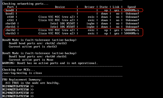
● Rubrik Operating System IP: These addresses are used by the Linux OS on each Rubik node. One IP addresses per node required from the same subnet. Rubrik node is configured with bond0 and bond1 as two separate networks. Both bond0 and bond1 networks support active-passive failover mode. Only bond0 network should configured for Cisco C-Series nodes connected to Cisco Fabric Interconnect. Once the Rubrik CDM software is installed on each node, Both Rubrik Management and Rubrik Data network are allocated in the same VLAN and configured in bond0 network.
● Once Rubrik cluster is configured, Customers have the option to configure sub-interfaces for Rubrik nodes. This allows accessibility to multiple networks through different VLANs.
Figure 10 elaborates on the network port (bond0). Only bond0 port should be configured for Cisco C-Series nodes connected to Cisco Fabric Interconnect.
Note: OS Installation through Intersight for FI-attached servers in IMM requires an In-Band Management IP address.(ref: https://intersight.com/help/saas/resources/adding_OSimage ). Deployments not using In-Band Management address can install OS by mounting the ISO through KVM.
Note: Rubrik CDM deployed on Cisco UCS C-Series Servers and attached to Cisco UCS Fabric Interconnect do not support IPMI configuration. In this configuration, Cisco UCS C-Series nodes are attached to Cisco Fabric Interconnect and do not utilize IPMI configuration. Therefore, in the below table the IPMI IPs are configured as 0.0.0.x
Note: Administrators deploying Rubrik CDM on standalone Cisco C-Series servers (not attached to Cisco Fabric Interconnect) can use the node CIMC address as the IPMI IP.
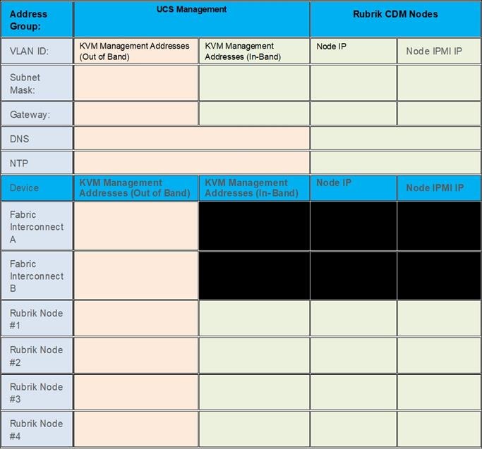
Note: Use the following tables to list the required IP addresses for the installation of a 4-node Rubrik CDM cluster and review an example IP configuration.
Note: Table cells shaded in black do not require an IP address.
Table 3. Rubrik Cluster IP Addressing
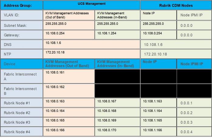
Note: Table 4 is a true representation of configuration deployed during Solution Validation.
Table 4. Example Rubrik Cluster IP Addressing
Prior to the installation, the required VLAN IDs need to be documented, and created in the upstream network if necessary. In present deployment the Rubrik Management and Backup Data traffic exist in the same VLAN on bond0 network. Customers can segregate Rubrik Management and Backup Data traffic by defining separate VLAN for Rubrik Management and Backup Data. Once the Rubrik cluster is bootstrapped and registered, customers can create sub-interfaces to segregate management and backup traffic.
Note: Ensure all VLANs are part of LAN Connectivity Policy defined in Cisco Server Profile for each C-Series node
Use the following tables to list the required VLAN information for the installation and review an example configuration.
| Name |
ID |
| <<rubrik-management-vlan>> |
1081 |
| <<rubrik-data-vlan>> |
1081 |
The Cisco UCS uplink connectivity design needs to be finalized prior to beginning the installation.
Use the following tables to list the required network uplink information for the installation and review an example configuration.
Table 6. Network Uplink Configuration
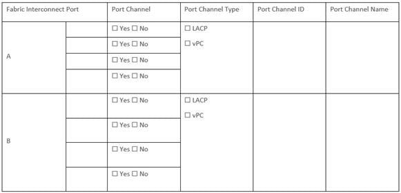
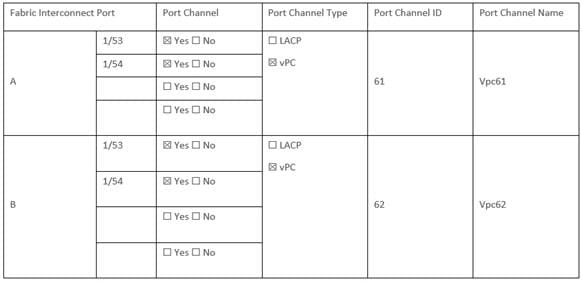
Table 7. Network Uplink Example Configuration
Create Cisco Intersight Account
Procedure 1. Create an account on Cisco Intersight
Note: Skip this step if you already have a Cisco Intersight account.
The procedure to create an account in Cisco Intersight is explained below. For more details, go to: https://intersight.com/help/saas/getting_started/create_cisco_intersight_account
Step 1. Go to https://intersight.com/ to create your Intersight account. You must have a valid Cisco ID to create a Cisco Intersight account.
Step 2. Click Create an account.
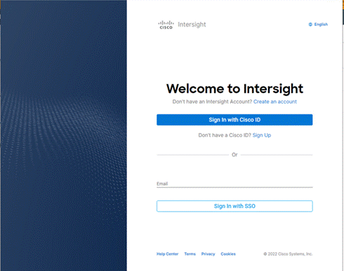
Step 3. Sign-In with your Cisco ID.
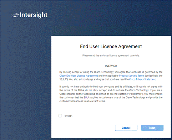
Step 4. Read the End User License Agreement and select I accept and click Next.
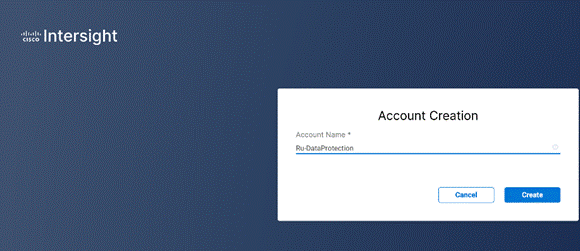
Step 5. Provide a name for the account and click Create.
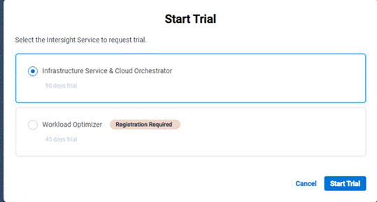
Step 6. Register for Smart Licensing or Start Trial.
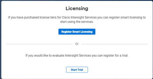
Step 7. Select Infrastructure Service & Cloud Orchestrator and click Start Trial.
Note: Go to: https://intersight.com/help/saas to configure Cisco Intersight Platform.
Set up Intersight Managed Mode (IMM)
Procedure 1. Set up Cisco Intersight Managed Mode on Cisco UCS Fabric Interconnects
The Cisco UCS fabric interconnects need to be set up to support Cisco Intersight managed mode. When converting an existing pair of Cisco UCS fabric interconnects from Cisco UCS Manager mode to Intersight Manage Mode (IMM), first erase the configuration and reboot your system.
Note: Converting fabric interconnects to Cisco Intersight managed mode is a disruptive process, and configuration information will be lost. You are encouraged to make a backup of their existing configuration. If a software version that supports Intersight Managed Mode (4.1(3) or later) is already installed on Cisco UCS Fabric Interconnects, do not upgrade the software to a recommended recent release using Cisco UCS Manager. The software upgrade will be performed using Cisco Intersight
Step 1. Configure Fabric Interconnect A (FI-A). On the Basic System Configuration Dialog screen, set the management mode to Intersight. All the remaining settings are similar to those for the Cisco UCS Manager Managed Mode (UCSM-Managed).
Cisco UCS Fabric Interconnect A
To configure the Cisco UCS for use in a FlexPod environment in ucsm managed mode, follow these steps:
Connect to the console port on the first Cisco UCS fabric interconnect.
Enter the configuration method. (console/gui) ? console
Enter the management mode. (ucsm/intersight)? intersight
The Fabric interconnect will be configured in the intersight managed mode. Choose (y/n) to proceed: y
Enforce strong password? (y/n) [y]: Enter
Enter the password for "admin": <password>
Confirm the password for "admin": <password>
Enter the switch fabric (A/B) []: A
Enter the system name: <ucs-cluster-name>
Physical Switch Mgmt0 IP address : <ucsa-mgmt-ip>
Physical Switch Mgmt0 IPv4 netmask : <ucs-mgmt-mask>
IPv4 address of the default gateway : <ucs-mgmt-gateway>
DNS IP address : <dns-server-1-ip>
Configure the default domain name? (yes/no) [n]: n
Default domain name :
Following configurations will be applied:
Management Mode=intersight
Switch Fabric=A
System Name=<ucs-cluster-name>
Enforced Strong Password=yes
Physical Switch Mgmt0 IP Address=<ucsa-mgmt-ip>
Physical Switch Mgmt0 IP Netmask=<ucs-mgmt-mask>
Default Gateway=<ucs-mgmt-gateway>
DNS Server=<dns-server-1-ip>
Apply and save the configuration (select 'no' if you want to re-enter)? (yes/no): yes
Step 2. After applying the settings, make sure you can ping the fabric interconnect management IP address. When Fabric Interconnect A is correctly set up and is available, Fabric Interconnect B will automatically discover Fabric Interconnect A during its setup process as shown in the next step.
Step 3. Configure Fabric Interconnect B (FI-B). For the configuration method, select console. Fabric Interconnect B will detect the presence of Fabric Interconnect A and will prompt you to enter the admin password for Fabric Interconnect A. Provide the management IP address for Fabric Interconnect B and apply the configuration.
Cisco UCS Fabric Interconnect B
Enter the configuration method. (console/gui) ? console
Installer has detected the presence of a peer Fabric interconnect. This Fabric interconnect will be added to the cluster. Continue (y/n) ? y
Enter the admin password of the peer Fabric interconnect: <password>
Connecting to peer Fabric interconnect... done
Retrieving config from peer Fabric interconnect... done
Peer Fabric interconnect Mgmt0 IPv4 Address: <ucsa-mgmt-ip>
Peer Fabric interconnect Mgmt0 IPv4 Netmask: <ucs-mgmt-mask>
Peer FI is IPv4 Cluster enabled. Please Provide Local Fabric Interconnect Mgmt0 IPv4 Address
Physical Switch Mgmt0 IP address : <ucsb-mgmt-ip>
Apply and save the configuration (select 'no' if you want to re-enter)? (yes/no): yes
Procedure 2. Set Up Cisco Intersight Resource Groups
A Resource Group represents a collection of resources. You can create a Resource Group to classify and manage resources. Resource Groups can be used for assigning resources to an organization. For more information, go to: https://intersight.com/help/saas/resources/RBAC#role-based_access_control_in_intersight
Note: In Cisco Intersight, all the resources and configurations in existing user accounts will automatically be placed in a default Resource Group, titled default Resource Group.
In this procedure, a Cisco Intersight organization is created where all Cisco Intersight Managed Mode configurations, including policies, are defined.
Step 1. Log into the Cisco Intersight portal.
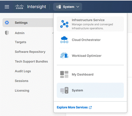
Step 2. Select System. Click Settings (the gear icon).
Step 3. Click Organizations.
Step 4. Click + Create Resource Groups.
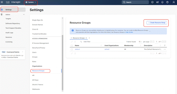
Step 5. Provide a name for the Resource group and click Create
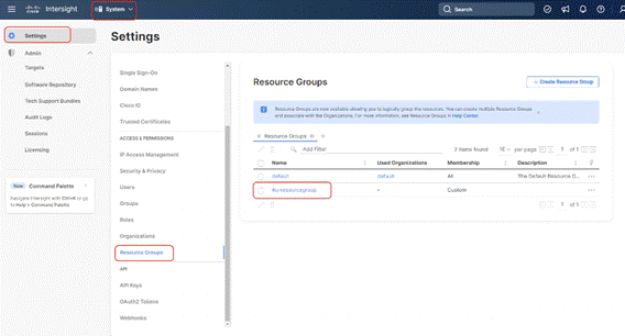
Procedure 3. Set Up Cisco Intersight Organization
An organization is a logical entity which enables multi-tenancy through separation of resources in an account. The organization allows you to use the Resource Groups and enables you to apply the configuration settings on a subset of targets.
Note: Administrators can use “default” organization. “Default” organization is automatically created once an Intersight account is created.
In this procedure, a Cisco Intersight organization is created where all Cisco Intersight Managed Mode configurations, including policies, are defined.
Step 1. Log into the Cisco Intersight portal.
Step 2. Select System. Click Settings (the gear icon).
Step 3. Click Organizations.
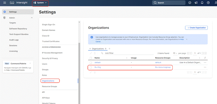
Step 4. Click + Create Organization
Step 5. Provide a name for the organization (for example, Ru-Org).
Step 6. Select the Resource Group created in the last step (for example, Ru-ResourceGroup).
Step 7. Click Create.
Procedure 4. Claim Cisco UCS Fabric Interconnects in Cisco Intersight
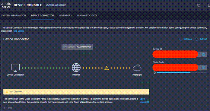
Note: Make sure the initial configuration for the fabric interconnects has been completed. Log into the Fabric Interconnect A Device Console using a web browser to capture the Cisco Intersight connectivity information.
Step 1. Use the management IP address of Fabric Interconnect A to access the device from a web browser and the previously configured admin password to log into the device.
Step 2. Under DEVICE CONNECTOR, the current device status will show “Not claimed.” Note or copy, the Device ID, and Claim Code information for claiming the device in Cisco Intersight.
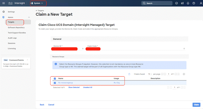
Step 3. Log into Cisco Intersight.
Step 4. Select System. Click Admin > Targets.
Step 5. Click Claim a New Target.
Step 6. Select Cisco UCS Domain (Intersight Managed) and click Start.

Step 7. Copy and paste the Device ID and Claim from the Cisco UCS FI to Intersight, select the Resource Group created in previous section and click Claim.
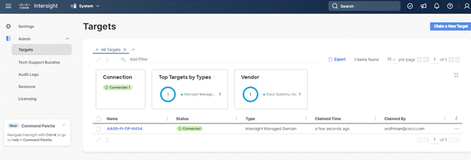
With a successful device claim, Cisco UCS FI should appear as a target in Cisco Intersight:
Step 8. In the Cisco Intersight window, click Settings and select Licensing. If this is a new account, all servers connected to the Cisco UCS domain will appear under the Base license tier. If you have purchased Cisco Intersight licenses and have them in your Cisco Smart Account, click Register and follow the prompts to register this Cisco Intersight account to your Cisco Smart Account. Cisco Intersight also offers a one-time 90-day trial of Advantage licensing for new accounts. Click Start Trial and then Start to begin this evaluation. The remainder of this section will assume Advantage licensing. A minimum of Cisco Intersight Essentials licensing is required to run the Cisco UCS C-Series platform in Intersight Managed Mode (IMM).
Procedure 5. Verify Addition of Cisco UCS Fabric Interconnects to Cisco Intersight
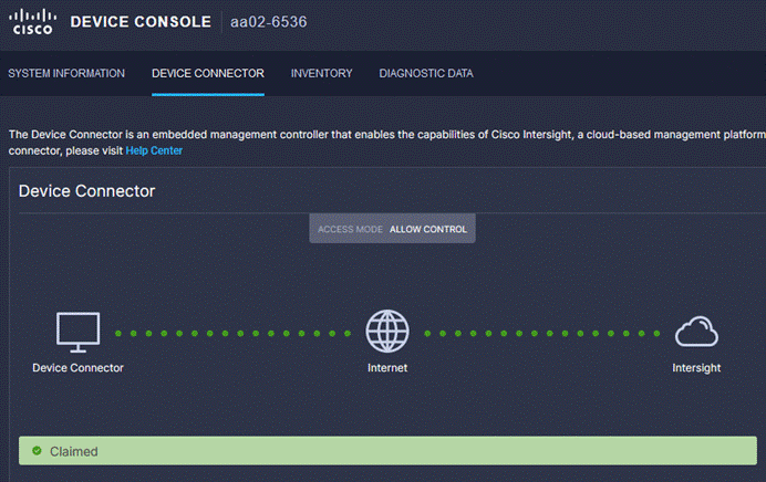
Step 1. Log into the web GUI of the Cisco UCS fabric interconnect and click the browser refresh button.
The fabric interconnect status should now be set to Claimed.
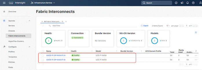
Step 2. Select Infrastructure Service.
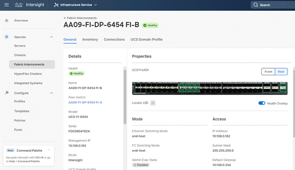
Step 3. Go to the Fabric Interconnects tab and verify the pair of fabric interconnects are visible on the Intersight dashboard.
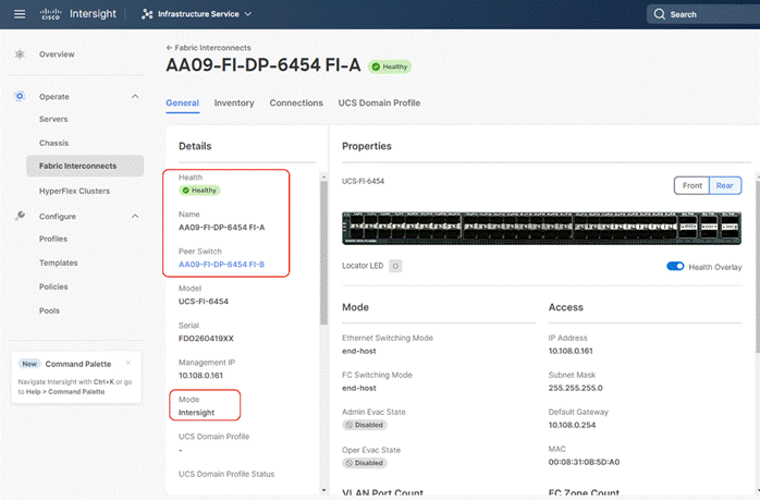
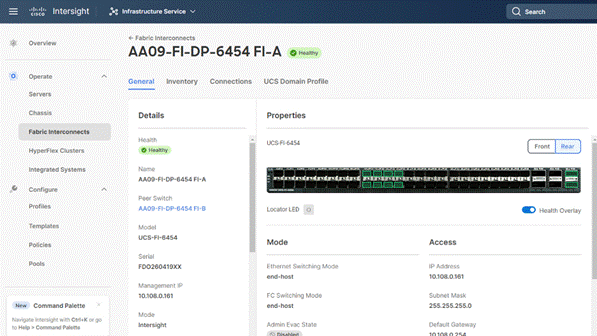
Step 4. You can verify whether a Cisco UCS fabric interconnect is in Cisco UCS Manager Managed Mode or Cisco Intersight managed mode by clicking the fabric interconnect name and looking at the detailed information screen for the fabric interconnect, as shown below:
Procedure 6. Upgrade Fabric Interconnect Firmware using Cisco Intersight
Note: If your Cisco UCS 6454 Fabric Interconnects are not already running firmware release 4.2(2c), upgrade them to 4.2(3d) or to the recommended release.
Note: If Cisco UCS Fabric Interconnects were upgraded to the latest recommended software using Cisco UCS Manager, this upgrade process through Intersight will still work and will copy the Cisco UCS firmware to the Fabric Interconnects.
Note: By default, Fabric Interconnect upgrades through Intersight are enabled with ‘Fabric Interconnect Traffic Evacuation. Since the present procedure is a new setup with no Domain Profile associated, Use Advanced Mode to exclude Fabric Interconnect traffic evacuation.
Step 1. Log into the Cisco Intersight portal.
Step 2. From the drop-down list, select Infrastructure Service and then select Fabric Interconnects under Operate.
Step 3. Click the ellipses “…”for either of the Fabric Interconnects and select Upgrade Firmware.
Step 4. Click Start.
Step 5. Verify the Fabric Interconnect information and click Next.
Step 6. Enable Advanced Mode and uncheck Fabric Interconnect traffic evacuation. This is only for new setup of Fabric Interconnects.
Step 7. Select 4.2(3d) release (or the latest release which has the Recommended icon) from the list and click Next.
Step 8. Verify the information and click Upgrade to start the upgrade process.
Step 9. Watch the Request panel of the main Intersight screen as the system will ask for user permission before upgrading each FI. Click the Circle with Arrow and follow the prompts on screen to grant permission.
Step 10. Wait for both the FIs to successfully upgrade.
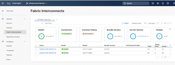
Step 11. Snap shot below details in the Fabric Interconnect upgrade to firmware version 4.2(3d)
A Cisco UCS domain profile configures a fabric interconnect pair through reusable policies, allows configuration of the ports and port channels, and configures the VLANs and VSANs in the network. It defines the characteristics of and configured ports on fabric interconnects. The domain-related policies can be attached to the profile either at the time of creation or later. One Cisco UCS domain profile can be assigned to one fabric interconnect domain.
Some of the characteristics of the Cisco UCS domain profile for Rubrik environment include:
● A single domain profile is created for the pair of Cisco UCS fabric interconnects.
● Unique port policies are defined for the two fabric interconnects.
● The VLAN configuration policy is common to the fabric interconnect pair because both fabric interconnects are configured for the same set of VLANs.
● The Network Time Protocol (NTP), network connectivity, and system Quality-of-Service (QoS) policies are common to the fabric interconnect pair.
Next, you need to create a Cisco UCS domain profile to configure the fabric interconnect ports and discover connected chassis. A domain profile is composed of several policies. Table 8 lists the policies required for the solution described in this document.
Table 8. Policies required for a Cisco UCS Domain Profile
| Policy |
Description |
| VLAN and VSAN Policy |
Network connectivity |
| Port configuration policy for fabric A |
Definition of Server Ports, FC ports and uplink ports channels |
| Port configuration policy for fabric B |
Definition of Server Ports, FC ports and uplink ports channels |
| Network Time Protocol (NTP) policy |
|
| Syslog policy |
|
| System QoS |
|
Procedure 1. Create VLAN configuration Policy
Step 1. Select Infrastructure Services.
Step 2. Under Policies, select Policy, then select UCS Domain, select the VLAN policy option and click Start.
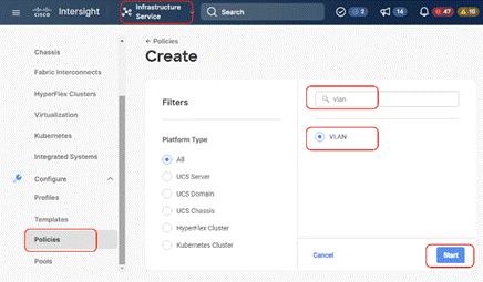
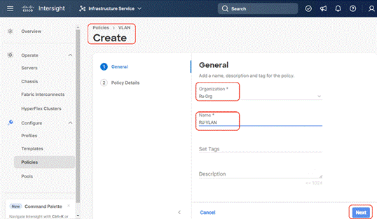
Step 3. Select organization, provide a name for the VLAN (for example, Ru-VLAN ) and click Next.
Step 4. Click Add VLANs to add your required VLANs.
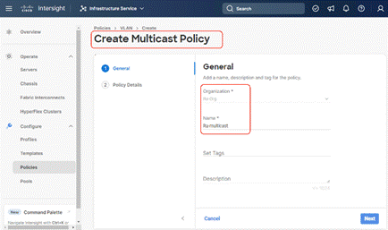
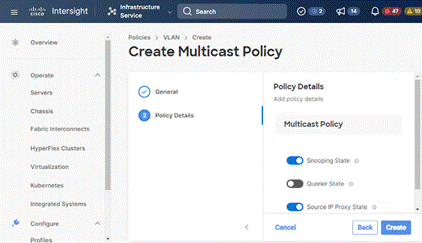
Step 5. Click Multicast Policy to add or create a multicast policy with default settings for your VLAN policy as show below:
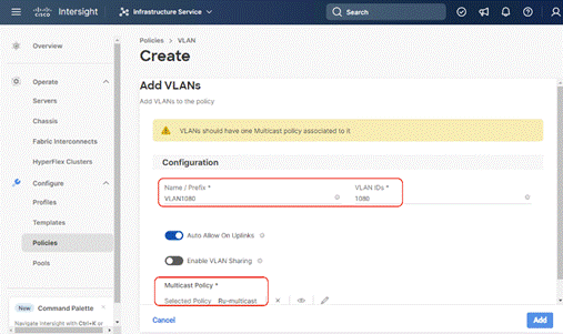
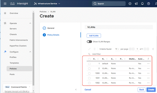
Step 6. Add additional VLANs as required with same multicast policy in the network setup and click Create.
Note: If you will be using the same VLANs on fabric interconnect A and fabric interconnect B, you can use the same policy for both.
Note: In the event any of the VLANs are marked native on the uplink Cisco Nexus switch, ensure to mark that VLAN native during VLAN Policy creation. This will avoid any syslog errors.
Procedure 2. Create Port Configuration Policy
Note: This policy has to be created for each of the fabric interconnects.
Step 1. Under Policies, for the platform type, select UCS Domain, then select Port and click Start.
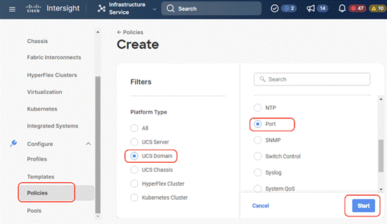
Step 2. Provide a name for the port policy, select the Switch Model (present configuration is deployed with FI 6454) and click Next.
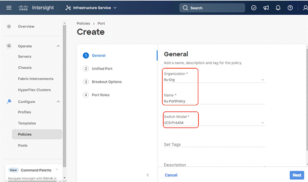
Step 3. Click Next. Define the port roles; server ports for chassis and server connections, Fibre Channel ports for SAN connections, or network uplink ports.
Step 4. If you need Fibre Channel, use the slider to define Fibre Channel ports.
Step 5. Select ports 1 through 16 and click Next, this creates ports 1-16 as type FC with Role as unconfigured. When you need Fibre Channel connectivity, these ports can be configured with FC Uplink/Storage ports.
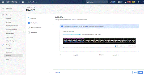
Step 6. Click Next.
Step 7. If required, configure the FC or Ethernet breakout ports, and click Next. In this configuration, no breakout ports were configured. Click Next.
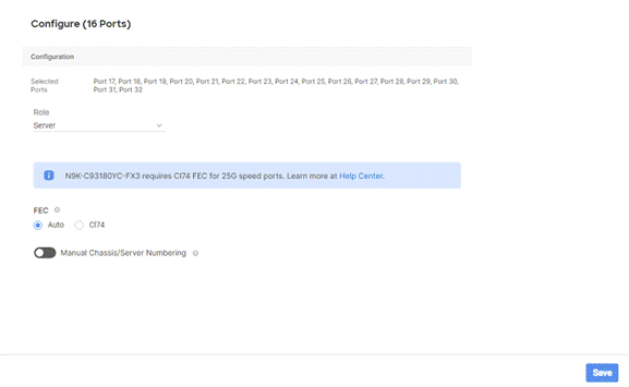
Step 8. To configure server ports, select the ports that have chassis or rack-mounted servers plugged into them and click Configure.
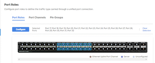
Step 9. From the drop-down list, select Server and click Save.
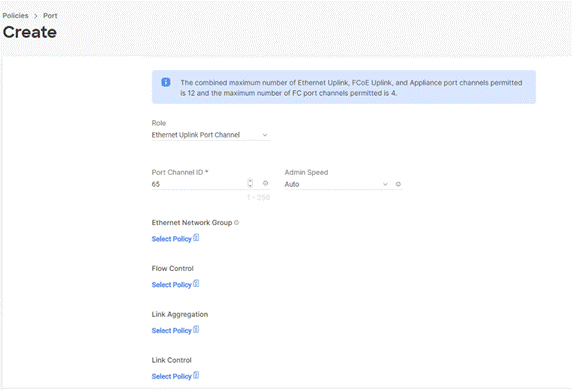
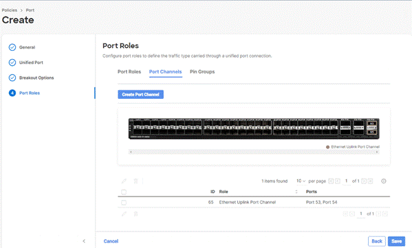
Step 10. Configure the uplink ports as per your deployment configuration. In this setup, port 53/54 are configured as uplink ports. Select the Port Channel tab and configure the port channel ID 65 ( or as defined in your configuration table) as per the network configuration. In this setup, port 53/54 are port channeled and provide uplink connectivity to the Cisco Nexus switch.
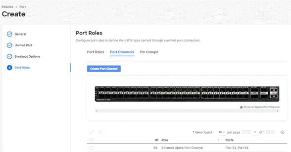
Step 11. Repeat this procedure to create a port policy for Fabric Interconnect B. Configure the port channel ID for Fabric B as per the network configuration. In this setup, the port channel ID 66 is created for Fabric Interconnect B, as shown below:
Procedure 3. Create NTP Policy
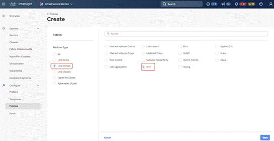
Step 1. Under Policies, select Create Policy, then select UCS Domain and then select NTP. Click Start.
Step 2. Provide a name for the NTP policy.
Step 3. Click Next.
Step 4. Define the name or IP address for the NTP servers. Define the correct time zone.
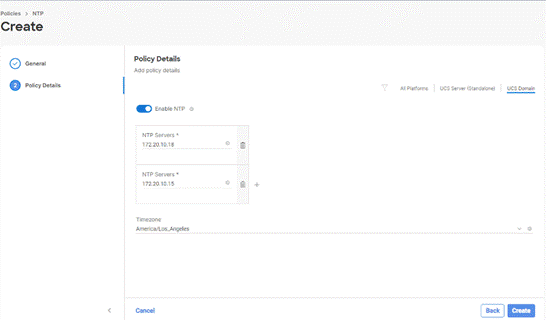
Step 5. Click Create.
Procedure 4. Create syslog Policy
Note: You do not need to enable the syslog server.
Step 1. Under Policies, select Create Policy, then select UCS Domain, and then select syslog. Click Start.
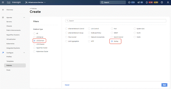
Step 2. Provide a name for the syslog policy.
Step 3. Click Next.
Step 4. Define the syslog severity level that triggers a report.
Step 5. Define the name or IP address for the syslog servers.
Step 6. Click Create.
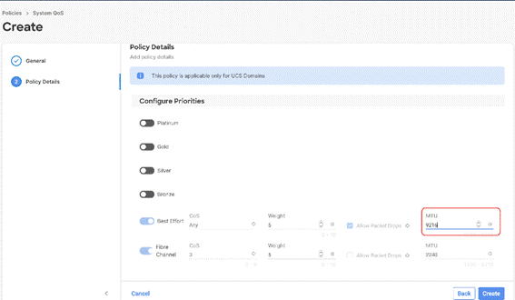
Procedure 5. Create QoS Policy
Note: QoS Policy should be created as per the defined QoS setting on uplink switch. In this Rubrik deployment, no Platinum/Gold/Silver, or Bronze Class of Service (CoS) were defined and thus all the traffic would go through best efforts.
Step 1. Under Policies, select Create Policy, select UCS Domain, then select System QoS. Click Start.
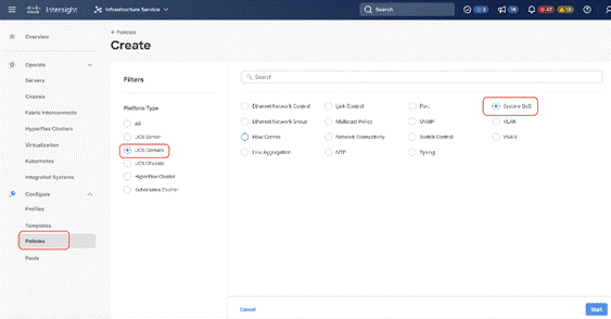
Step 2. Provide a name for the System QoS policy.
Step 3. Click Next.
Step 4. In this Rubrik configuration, no Platinum/Gold/Silver, or Bronze Class of Service (CoS) were defined and thus all the traffic would go through best efforts. Change the MTU of best effort to 9216. Click Create.
Note: All the Domain Policies created in this procedure will be attached to a Domain Profile. You can clone the Cisco UCS domain profile to install additional Cisco UCS Systems. When cloning the Cisco UCS domain profile, the new Cisco UCS domains use the existing policies for consistent deployment of additional Cisco Systems at scale.
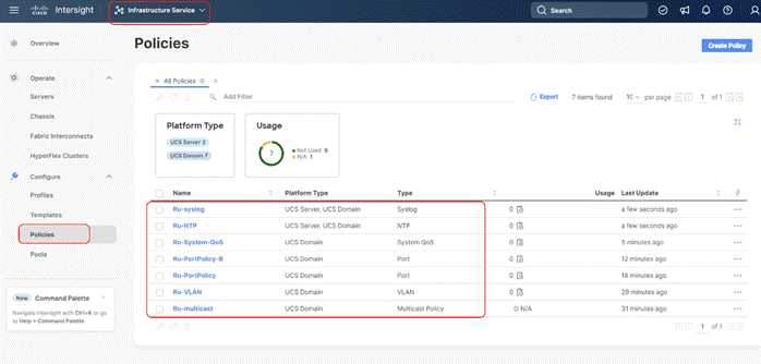
In the previous section, the following polices were created to successfully configure a Domain Profile
1. VLAN Policy and multicast policy
2. Port Policy for Fabric Interconnect A and B
3. NTP Policy
4. Syslog Policy
5. System QoS
The screenshot below displays the Policies created to configure a Domain Profile:
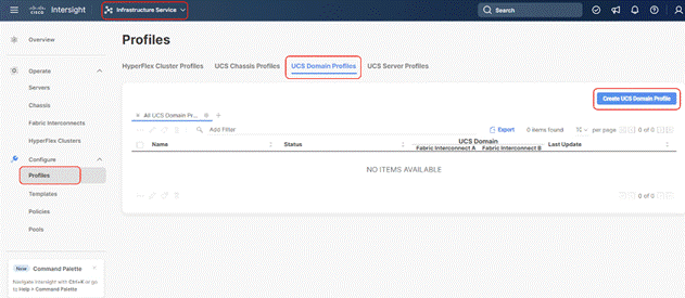
Procedure 6. Create Domain Profile
Step 1. Select the Infrastructure Service option and click Profiles.
Step 2. Select UCS Domain Profiles.
Step 3. Click Create UCS Domain Profile.
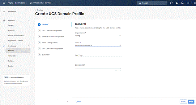
Step 4. Provide a name for the profile (for example, AA08-XSeries-DomainProfile) and click Next.
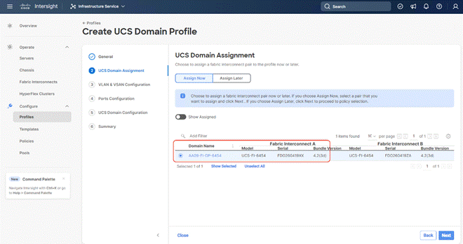
Step 5. Select the fabric interconnect domain pair created when you claimed your Fabric Interconnects.
Step 6. Under VLAN Configuration, click Select Policy to select the policies created earlier. (Be sure that you select the appropriate policy for each side of the fabric.) In this configuration the VLAN policy is same for both the fabric interconnects.
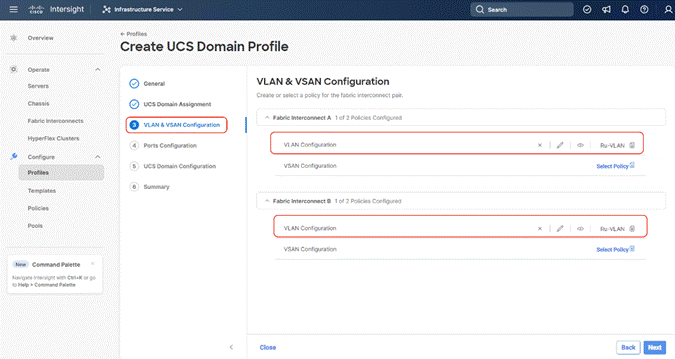
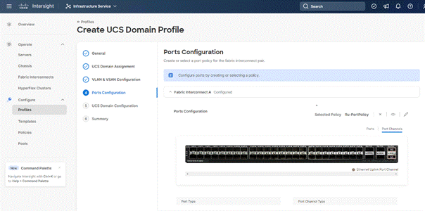
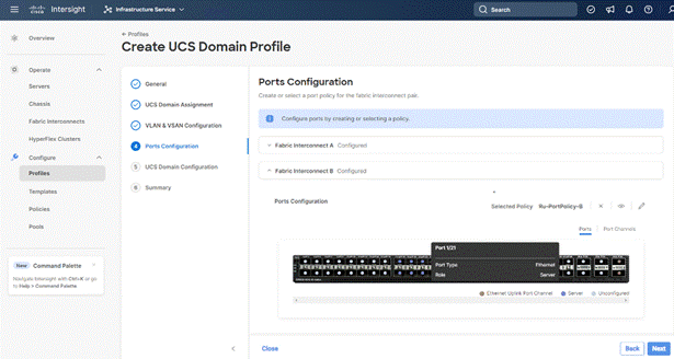
Step 7. Under Ports Configuration, select the port configuration policies created earlier. Each fabric has different port configuration policy with only the port channel ID different across both the Port Configuration Policy. Therefore, you need to select separate Port Policy for each Fabric Interconnect.
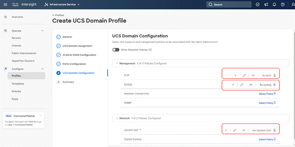
Step 8. Under UCS Domain Configuration, select syslog, System QoS, and the NTP policies created earlier. Click Next.
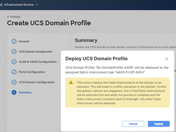
Step 9. Review the Summary and click Deploy. Accept the warning for the Fabric Interconnect reboot and click Deploy.
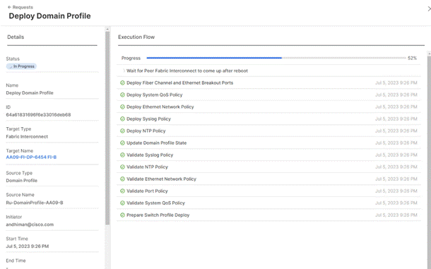
Step 10. Monitor the Domain Profile deployment status and ensure the successful deployment of Domain Profile.
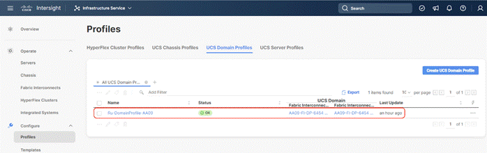
Step 11. After the Cisco UCS domain profile has been successfully created and deployed, the policies, including the port policies, are pushed to Cisco UCS fabric interconnects. Screenshot below details successful configuration of Domain Profile on Cisco UCS Fabric Interconnect in IMM mode (Intersight Managed Mode).
Step 12. Verify the uplink and Server ports are online across both Fabric Interconnects. In the event, the uplink ports are not green, please verify the configuration on the uplink Nexus switches.
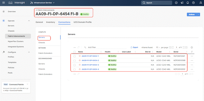
In the Port Policy, port 17-32 were defined as Server Ports. The 4x C240 M6 LFF certified for Rubrik deployment were already attached to these ports. The Servers are automatically discovered when the Domain Profile is configured on the Fabric Interconnects.
Step 13. To view the servers, go to the Connections tab and select Servers from the right navigation bar.
A server profile template enables resource management by simplifying policy alignment and server configuration. You can create a server profile template by using the server profile template wizard, which groups the server policies into the following categories to provide a quick summary view of the policies that are attached to a profile:
● Pools: KVM Management IP Pool, MAC Pool and UUID Pool.
● Compute policies: Basic input/output system (BIOS), boot order policy.
● Network policies: Adapter configuration and LAN policies.
◦ The LAN connectivity policy requires you to create an Ethernet network group policy, Ethernet network control policy, Ethernet QoS policy and Ethernet adapter policy.
● Storage policies for RAID1 configuration of internal M.2 cards. This is required for Rubrik OS installation.
● Management policies: IMC Access Policy for Rubrik certified Cisco C240 M6 LFF node, Intelligent Platform Management Interface (IPMI) over LAN; local user policy.
Procedure 1. Create Out of Band IP Pool
The IP Pool is a group of IP for KVM access, Server management and IPMI access of Rubrik Certified nodes. The management IP addresses used to access the CIMC on a server can be out-of-band (OOB) addresses, through which traffic traverses the fabric interconnect via the management port.
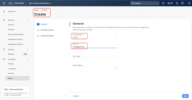
Step 1. Click Infrastructure Service, select Pool, and click Create Pool.
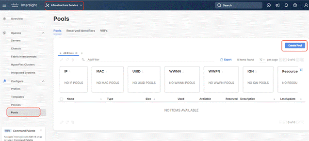
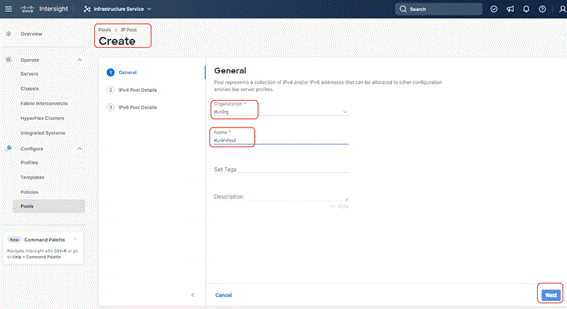
Step 2. Select IP and click Start.
Step 3. Select Organization, Enter a Name for IP Pool and click Next.
Step 4. Enter the required IP details and click Next.
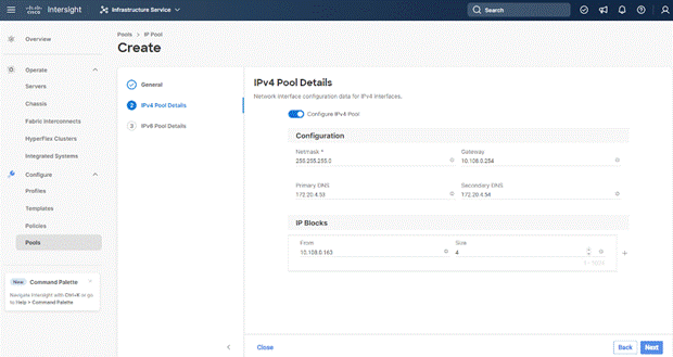
Step 5. Deselect the IPV6 configuration and click Create.
Procedure 2. Create In-Band IP Pool
The IP Pool is a group of IP for KVM access, Server management and IPMI access of Rubrik Certified nodes. The management IP addresses used to access the CIMC on a server can be inband addresses, through which traffic traverses the fabric interconnect via the fabric uplink port.
Note: Since vMedia is not supported for out-of-band IP configurations, the OS Installation through Intersight for FI-attached servers in IMM requires an In-Band Management IP address. For more information, go to: https://intersight.com/help/saas/resources/adding_OSimage.
Step 1. Click Infrastructure Service, select Pool, and click Create Pool.

Step 2. Select IP and click Start.
Step 3. Select Organization, Enter a Name for IP Pool and click Next.
Step 4. Enter the required IP details and click Next.
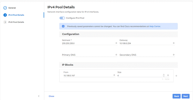
Step 5. Deselect the IPV6 configuration and click Create.
Procedure 3. Create MAC Pool
Note: Best practices mandate that MAC addresses used for Cisco UCS domains use 00:25:B5 as the first three bytes, which is one of the Organizationally Unique Identifiers (OUI) registered to Cisco Systems, Inc. The remaining 3 bytes can be manually set. The fourth byte (for example, 00:25:B5:xx) is often used to identify a specific UCS domain, meanwhile the fifth byte is often set to correlate to the Cisco UCS fabric and the vNIC placement order.
Note: Create two MAC Pools for the vNIC pinned to each of the Fabric Interconnect (A/B). This allows easier debugging during MAC tracing either on Fabric Interconnect or on the uplink Cisco Nexus switch.
Step 1. Click Infrastructure Service, select Pool, and click Create Pool.
Step 2. Select MAC and click Start.
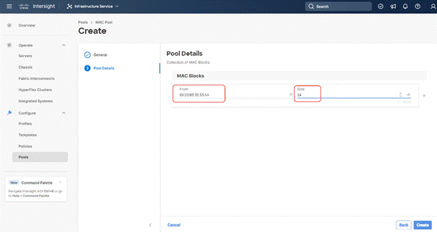
Step 3. Select organization, Enter a Name for Mac Pool (A) and click Start.
Step 4. Enter the last three octet of MAC address and the size of the Pool and click Create.
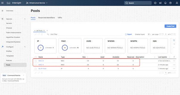
Step 5. Repeat this procedure for the MAC Pool for the vNIC pinned to Fabric Interconnect B, shown below:
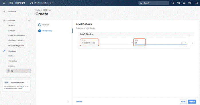
The screenshot below details two MAC Pool for each virtual NIC (vNIC) pinned to each Fabric Interconnect:
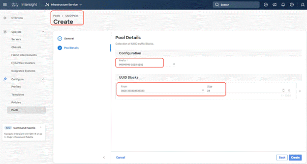
Procedure 4. Create UUID Pool
Step 1. Click Infrastructure Service, select Pool, and click Create Pool.
Step 2. Select UUID and click Start.
Step 3. Select Organization, Enter a Name for UUID Pool and click Next.
Step 4. Enter a UUID Prefix (the UUID prefix must be in hexadecimal format xxxxxxxx-xxxx-xxxx).
Step 5. Enter UUID Suffix (starting UUID suffix of the block must be in hexadecimal format xxxx-xxxxxxxxxxxx).
Step 6. Enter the size of the UUID Pool and click Create. The details are shown below:
Procedure 1. Create BIOS Policy
Table 9 lists the required polices for the BIOS policy.
Table 9. Policies required for domain profile
| Option |
Settings |
| Memory -> Memory Refresh Rate |
1x Refresh |
| Power and Performance -> Enhanced CPU Performance |
Auto |
| Processor -> Boot Performance Mode |
Max Performance |
| Processor -> Energy-Performance |
Performance |
| Processor -> Processor EPP Enable |
enabled |
| Processor -> EPP Profile |
Performance |
| Processor -> Package C State Limit |
C0 C1 state |
| Serial Port -> Serial A Enable |
enabled |
Step 1. Click Infrastructure Service, select Policies, and click Create Policy.
Step 2. Select UCS Server, BIOS and click Start.
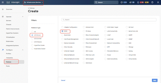
Step 3. Select Organization and enter a name for BIOS Policy.
Step 4. Select UCS Server (FI-Attached), In the policy detail page, select processor option (+) and change the below options and click Create:
● Boot Performance Mode to Max Performance
● Energy Performance to Performance
● Processor EPP Enable to Enable
● EPP Profile to Performance
● Package C State Limit to C0 C1 State
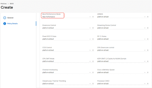
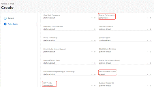
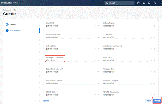
Step 5. Click Create.
Procedure 2. Create IPMI over LAN Policy
Note: The highest privilege level that can be assigned to an IPMI session on a server. All standalone rack servers support this configuration. FI-attached rack servers with firmware at minimum of 4.2.3a support this configuration.
Note: The encryption key to use for IPMI communication. It should have an even number of hexadecimal characters and not exceed 40 characters.
Step 1. Click Infrastructure Service, select Policies, and click Create Policy.
Step 2. Select UCS Server, IPMI over LAN and click Start.
Step 3. Select Organization, Name the IPMI Over LAN policy, then click Next.
Step 4. Select UCS Server (FI-Attached).
Step 5. For the Privilege Level, select admin and enter an encryption key.
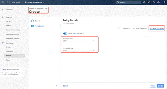
Step 6. Click Save.
Procedure 3. Create Storage Policy
The Storage policy allows you to create drive groups, virtual drives, configure the storage capacity of a virtual drive, and configure the M.2 RAID controllers.
In this configuration, Rubrik certified C240 M6 LFF nodes are configured with:
● 2x M.2 SSDs managed through M2 RAID Controller. A RAID1 configuration would be created across these drives.
● 12x Large Form Factor (LFF) drives managed through pass through SAS controller. These drives are configured in JBOD mode.
Step 1. Click Infrastructure Service, select Policies, and click Create Policy.
Step 2. Select UCS Server, Storage and click Start.
Step 3. Select Organization, Name the Storage policy, then click Next.
Step 4. Select UCS Server (FI-Attached).
Step 5. Change the Default Drive State’ to JBOD
Step 6. Enable M.2 RAID Configuration and select MSTOR-RAID-1 (MSTOR-RAID). (All Changes are marked in RED).
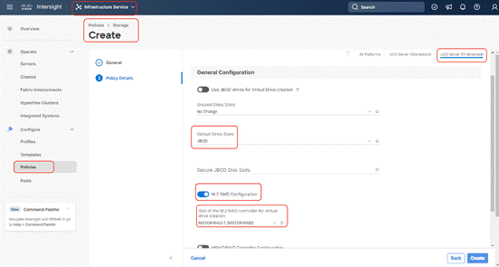
Step 7. Click Create.
LAN Connectivity Policy
LAN Connectivity Policy determines the connections, and the network communication resources between the server and the LAN on the network. Some of the key best practices which should be considered before creating a LAN Connectivity Policy for Rubrik nodes are explained below:
● To allow network access to Rubrik nodes, the LAN connectivity policy is used to create (four)4x virtual network interfaces (vNICs); vNIC0, vNIC1, vNIC2, VNIC3. vNIC0 and vNIC1 are pinned to Switch ID A and Switch ID B respectively, similarly vNIC2 and vNIC3 are pinned on Switch ID A and Switch ID B respectively, with the same Ethernet network group policy, Ethernet network control policy, Ethernet QoS policy and Ethernet adapter policy.
● Even though (four) 4x vNICs only (two)2 vNICs (vNIC2 and vNIC3) were created and are configured through Rubrik OS. vNIC0 and vNIC1 are never used by Rubrik OS. Four vNICs are created to ensure compatibility of configuration between C-Series nodes connect to Cisco Fabric Interconnect and standalone Cisco UCS C-Series nodes which allow Cisco UCS VIC directly connected to a uplink switch such as Cisco Nexus 9000 series.
● The primary network VLAN for Rubrik should be marked as native or the primary network VLAN should be tagged at the uplink switch.
● The two vNICs (vNIC2/vNIC3) managed by Rubrik for all UCS Managed mode or Intersight Managed mode (connected to Cisco UCS Fabric) should be in Active-Backup mode (bond mode 1). C-Series nodes connected to Cisco Fabric Interconnect does not support Active-Active mode ( 802.3ad / mode 4). Ref. https://www.cisco.com/c/en/us/support/docs/servers-unified-computing/ucs-b-series-blade-servers/200519-UCS-B-series-Teaming-Bonding-Options-wi.html
Figure 11 shows the mapping of VNIC2 and vNIC3 created in LAN connectivity Policy to network ports as identified on Rubrik nodes.
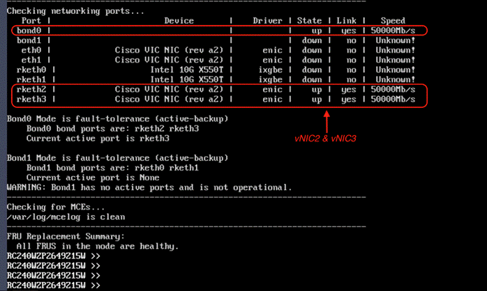
Table 10 lists the policy details which would be created through Intersight.
Table 10. LAN connectivity Policy details
| Network Port |
Mac Pool |
Switch ID |
PCI Order |
OS mapping |
| vNIC0 |
MAC Pool A |
A |
0 |
eth0 |
| vNIC1 |
MAC Pool B |
B |
1 |
eth1 |
| vNIC2 |
MAC Pool A |
A |
2 |
rketh2 |
| vNIC3 |
MAC Pool B |
B |
3 |
rketh3 |
Procedure 4. Create LAN Connectivity Policy
Step 1. Click Infrastructure Service, select Policies, and click Create Policy.
Step 2. Select UCS Server, then select Lan Connectivity Policy and click Start.
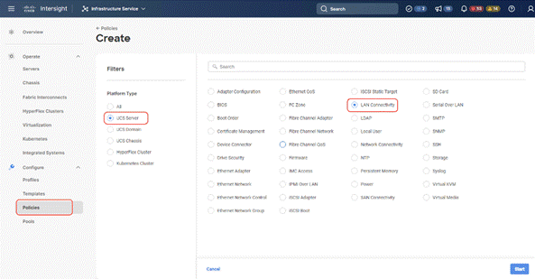
Step 3. Select Organization, Name the LAN Connectivity Policy and select UCS Server (FI Attached).
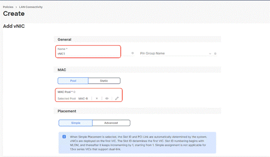
Step 4. Click Add vNIC.
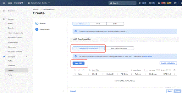
Step 5. Name the vNIC “vNIC0.”
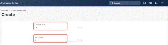
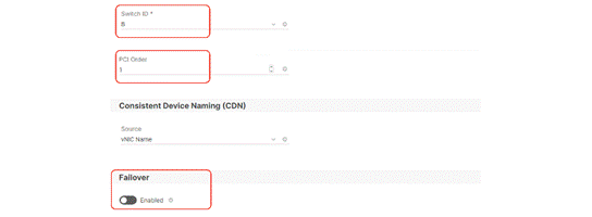
Step 6. For the for vNIC Placement, select Advanced.
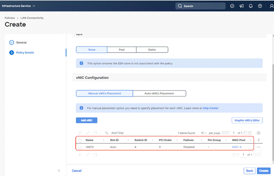
Step 7. Select MAC Pool A previously created, Switch ID A, PCI Order 0.
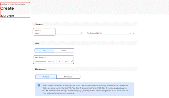
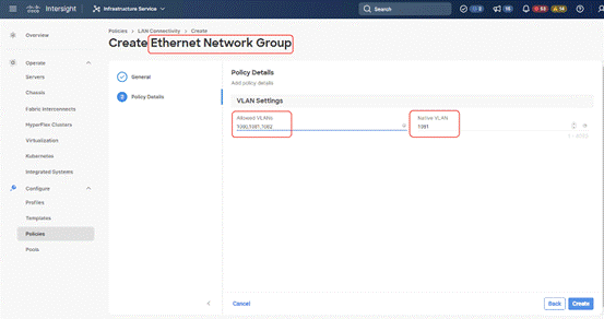
Step 8. Create the Ethernet Network Group Policy; add the allowed VLANs and add the native VLAN. The primary network VLAN for Rubrik should be marked as native or the primary network VLAN should be tagged at the uplink switch.
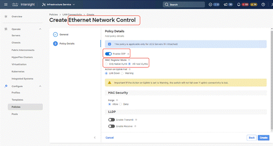
Step 9. Create the Ethernet Network Control policy; name the policy, enable CDP, set MAC Register Mode as All Host VLANs, and keep the other settings as default.
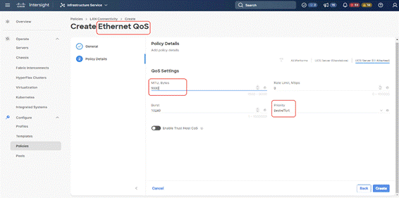
Step 10. Create the Ethernet QoS Policy; edit the MTU to 9000 and keep the Priority as best-effort.
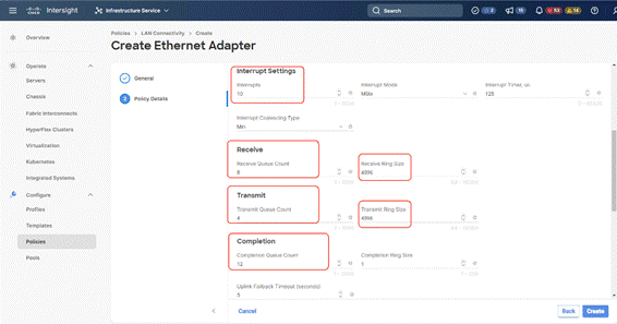
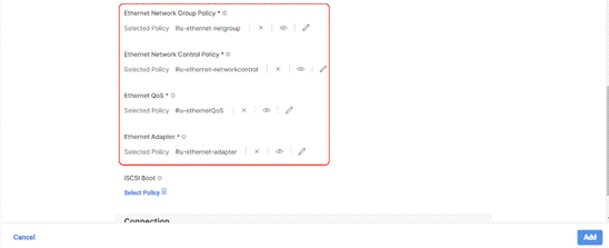
Step 11. Create the Ethernet Adaptor Policy; select UCS Server (FI-Attached), Interrupts=10, Receive Queue Count = 8 Receive Ring Size =4096, Transmit Queue Count = 4, Transmit Ring Size = 4096, Completion Queue = 12, keep the others as default, ensure Receive Side Scaling is enabled.
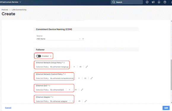
Step 12. Ensure the four policies are attached and Enable Failover is disabled (default). Click Add.
Step 13. Add vNIC as vNIC1. Select the same setting as vNIC0.
Step 14. For Switch ID, select B, and the PCI Order should be 1.
Step 15. Optional. The MAC Pool can be selected as the MAC Pool for Fabric B.
Step 16. Select the Ethernet Network Group Policy, Ethernet Network Control Policy, Ethernet QoS, and Ethernet Adapter policy as created for vNIC0 and click Add.
Step 17. Repeat steps 1 – 16 to add vNIC2 and vNIC3.
Step 18. vNIC2 and vNIC3 will have the same Ethernet Network Group Policy, Ethernet Network Control Policy, Ethernet QoS, and Ethernet Adapter policy as created for vNIC0 and VNIC1.
● vNIC2 needs to be pinned to Switch ID A, with AMC Pool B and PCI Order as 2.
● vNIC2 needs to be pinned to Switch ID B, with MAC Pool B and PCI Order as 3, select B, and the PCI Order should be 1.
Step 19. Ensure the LAN connectivity Policy is created as shown below with 4x vNIC and click Create.
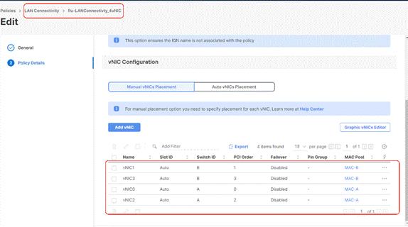
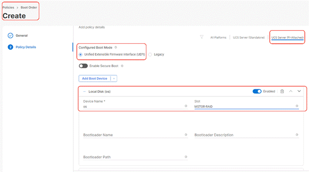
Procedure 5. Create Boot Order Policy
The boot order policy is configured with the Unified Extensible Firmware Interface (UEFI) boot mode. The following are the Boot Order mapping for Rubrik nodes:
● PXE Boot
● Virtual Media to mount ISO
● Virtual Drive with RAID1 created across (two)2x M.2 boot drives. Rubrik OS is installed on this Virtual Drive.
Step 1. Click Infrastructure Service, select Policies, and click Create Policy.
Step 2. Select UCS Server, Boot Order, and click Start.
Step 3. Select Organization, Enter a Name for Boot Order Policy.
Step 4. Under Policy Detail, select UCS Server (FI Attached), and ensure UEFI is checked.
Step 5. Select Add Boot Device and select local disk and enter device name as ‘os’ and Slot as ‘MSTOR-RAID.’
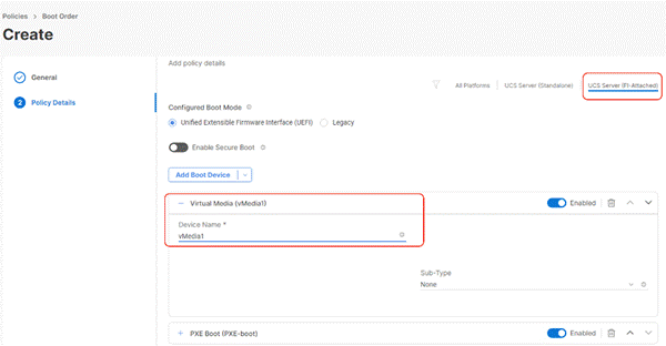
Step 6. Select Add Boot Device and click vMedia and name the ‘vmedia-1’ device name.
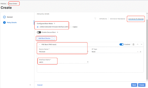
Step 7. Select Add Boot Device and select PXE Boot, enter device name as ‘PXE-boot’ and interface name as vNIC0.
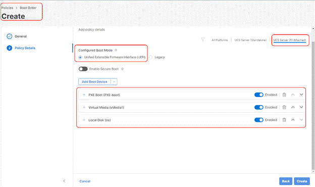
Step 8. Ensure the boot Device Order is as provided in the following screenshot, with 1st Boot Order as PXE boot, 2nd Boot Order as vMedia and 3rd Boot Order as os(local disk). Click Create.
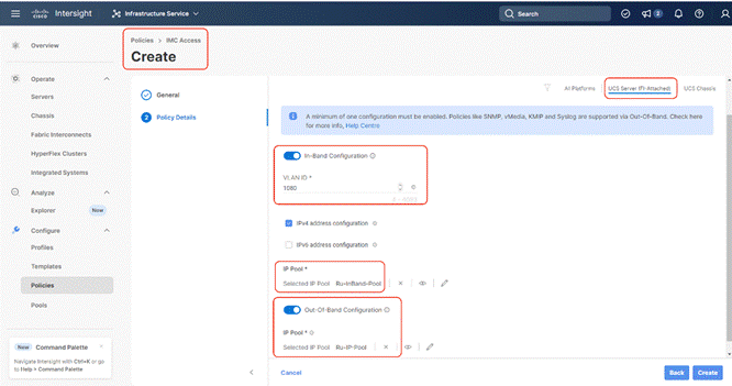
Procedure 6. Create IMC Access Policy
The IMC Access policy allows you to configure your network and associate an IP address from an IP Pool with a server. In-Band IP address, Out-Of-Band IP address, or both In-Band and Out-Of-Band IP addresses can be configured using IMC Access Policy and is supported on Drive Security, SNMP, Syslog, and vMedia policies.
In the present Rubrik configuration, customers can create both IN-Band Out of Band IMC Access Policy.
Note: In-Band IMC Access Policy is required to utilize operating system installation feature of Cisco Intersight.
Step 1. Click Infrastructure Service, select Policies, and click Create Policy.
Step 2. Select UCS Server, then select IMC Access and click Start.
Step 3. Select Organization, Name the IMC Access policy, then click Next.
Step 4. Select UCS Server (FI-Attached).
Step 5. Select the In-Band Configuration option.
Step 6. Enter VLAN for IN-Band Access and select the IN-Band IP Pool created during IP Pool configuration.
Step 7. Enable Out-of-Band (OOB) configuration, Select IP Pool ( as created under ‘Create Pools’) section.
Step 8. Click Create.
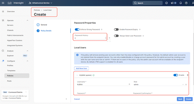
Procedure 7. Create Local User Policy
Note: Local User Policy creates local user and password for access to KVM through Server Management IP allocated through IMC Access Policy. For example, access to server console through https://<<KVM-IP>>/kvm/.
Step 1. Click Infrastructure Service, select Policies, and click Create Policy.
Step 2. Select UCS Server, then select Local User and click Start.
Step 3. Select Organization, Name the Local User policy and click Next.
Step 4. Change the password history to ‘0’, Add a local user with the name ‘RUBRIK’ and role as admin and enter a password. This is used to access the server KVM through KVM IP. Click Create. You can create multiple Local Users as required.
Procedure 1. Create Server Profile Template
A server profile template enables resource management by simplifying policy alignment and server configuration. All the policies created in previous section would be attached to Server Profile Template. You can derive Server Profiles from templates and attach to new Cisco UCS C-Series nodes deployed for Rubrik cluster. For more information, go to: https://www.intersight.com/help/saas/features/servers/configure#server_profiles
The pools and policies attached to Server Profile Template are listed in Table 11.
Table 11. Policies required for Server profile template
| Pools |
Compute Policies |
Network Policies |
Management Policies |
Storage Policy |
| KVM Management IP Pool for In-Band and Out-of-Band (OOB) Access |
BIOS Policy |
LAN Connectivity Policy |
IMC Access Policy |
Rubrik storage policy for RAID1 configuration across 2x M.2 cards. This is utilized for Rubrik OS installation |
| MAC Pool for Fabric A/B |
Boot Order Policy |
Ethernet Network Group Policy |
IPMI over LAN |
|
| UUID Pool |
|
Ethernet Network Control Policy |
Local User Policy |
|
|
|
|
Ethernet QoS Policy |
Serial Over LAN Policy |
|
|
|
|
Ethernet Adapter Policy |
|
|
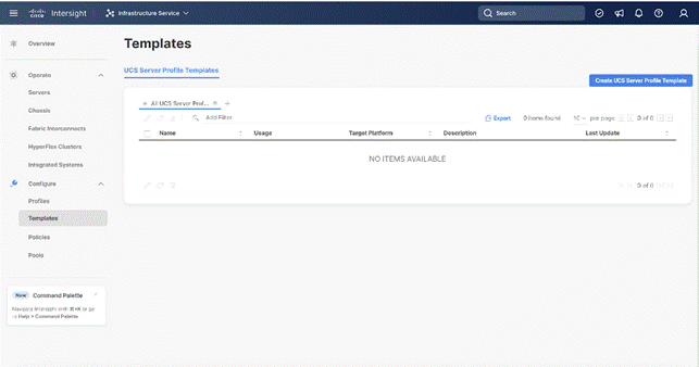
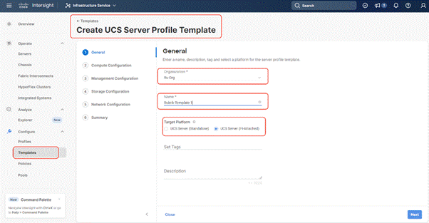
Step 1. Click Infrastructure Service, select Templates, and click Create UCS Server Profile Template.
Step 2. Select Organization, Name the Server Profile Template, select UCS Sever (FI-Attached) and click Next.
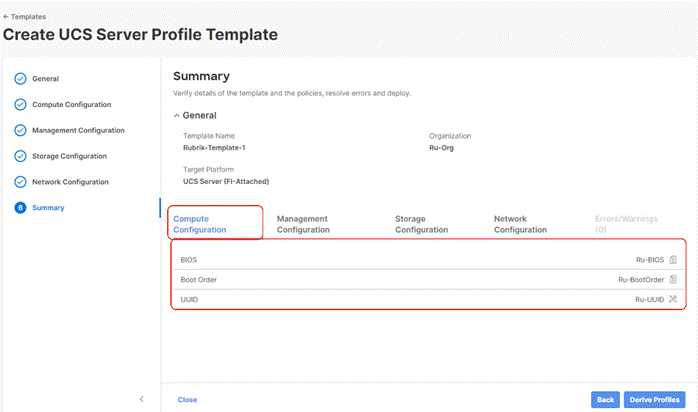
Step 3. Select UUID Pool and all Compute Policies (BIOS and Boot Order Policy) created in the previous section. Click Next.
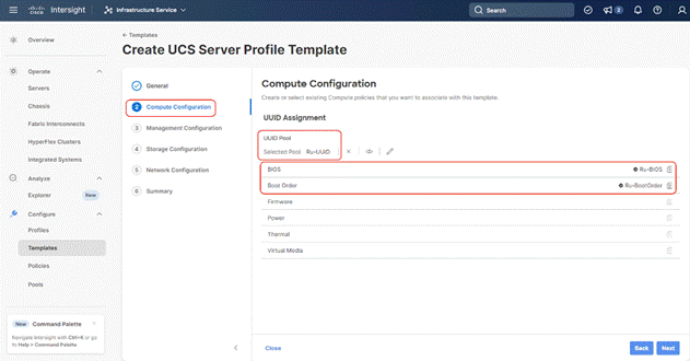
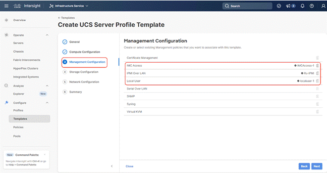
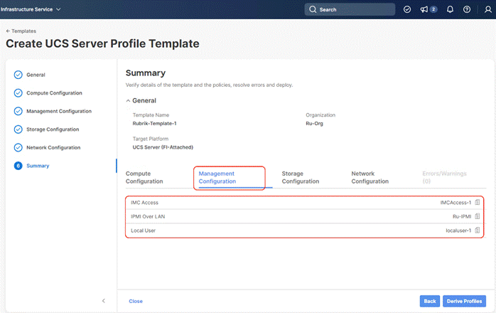
Step 4. Select all Management Configuration Policies ( IMC Access, IPMI over LAN and Local User policies ) and attach to the Server Profile Template.
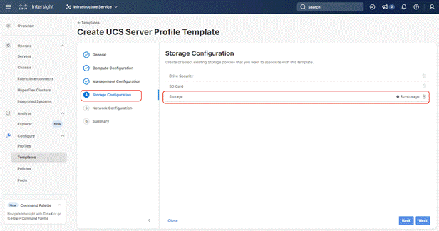
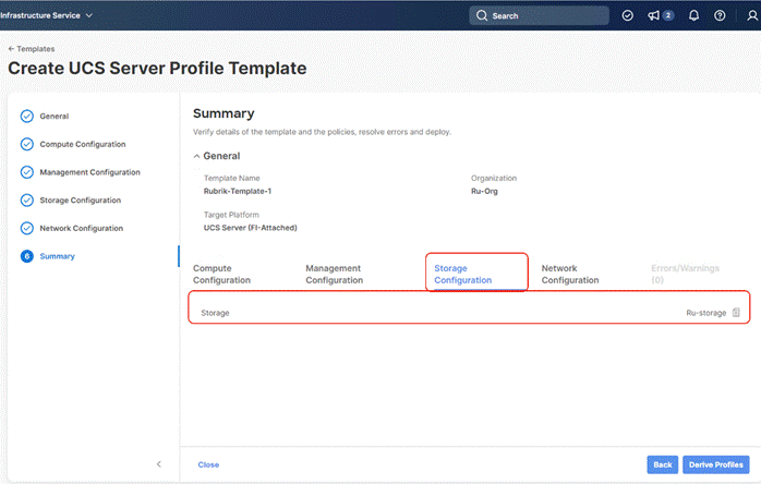
Step 5. In the next screen, under Storage Configuration, Select Storage Policy and click Next.
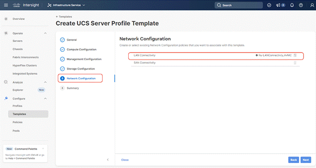
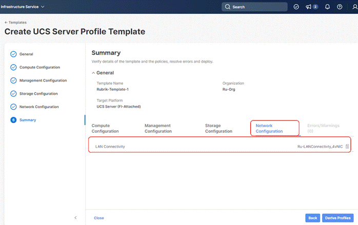
Step 6. Under Network Configuration, select the LAN connectivity Policy created in the previous section and click Next.
Step 7. Verify the summary and click Close. This completes the creation of Server Profile Template The details of the policies attached to the Server Profile Template are detailed below.
Install Rubrik CDM on Cisco UCS C-Series Nodes
Rubrik OS can be installed on Rubrik certified Cisco UCS C240 M6 LFF nodes with one of two options:
● Install OS through Intersight OS installation.
This allows installing the Rubrik CDM operating System through Cisco Intersight. You are required to have an Intersight Advantage license for this feature. The operating system resides on a local software repository as an OS Image Link configured in Cisco Intersight. The repository can be a HTTTPS, NFS or CIFS repository accessible through the KVM management network. This feature benefits in the following ways:
◦ It allows the operating system installation simultaneously across several C-Series nodes provisioned for the Rubrik CDM cluster.
◦ It reduces Day0 installation time by avoiding mounting the ISO as Virtual Media on the KVM console for each node deployed for Rubrik on each Cisco UCS C-Series node.
● Install the OS by mounting ISO as virtual Media for each node.
Derive and Deploy Server Profiles
Procedure 1. Derive and Deploy Server Profiles
In this procedure, Server Profiles are derived from Server Profile Template and deployed on Cisco C-Series nodes certified for the Rubrik CDM.
Step 1. Select Infrastructure Service, then select Templates and identify the Server Template created in the previous section.
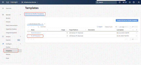
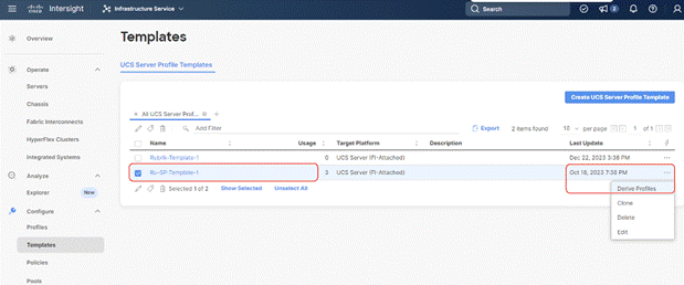
Step 2. Select the Server Template created in previous section, click the … icon and select Derive Profiles.
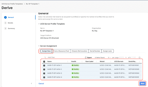
Step 3. Identify and select the Cisco UCS C-Series nodes for Server Profile deployment and click Next.
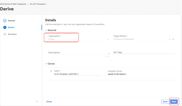
Step 4. Select organization (Ru-Org in this deployment), edit the name of Profiles if required and click Next.
Step 5. All Server policies attached to the template will be attached to the derived Server Profiles. Click Derive.
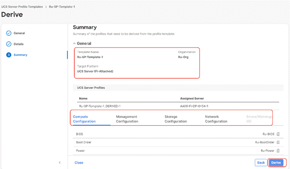
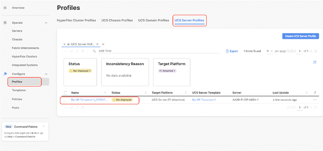
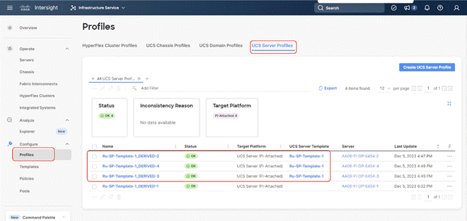
Step 6. The Server Profiles will be validated and ready to be deployed to the Cisco UCS C-Series. A “Not Deployed” icon will be displayed on the derived Server Profiles.
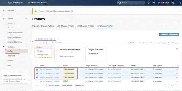
Step 7. Select the Not Deployed Server Profiles, click the … icon and click Deploy.
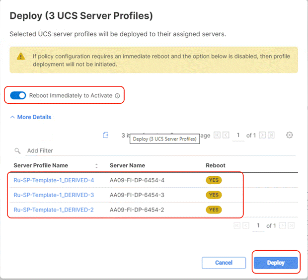
Step 8. Enable Reboot Immediately to Activate and click Deploy.
Step 9. Monitor the Server Profile deployment status and ensure the Profile deploys successfully to the Cisco UCS C-Series node.
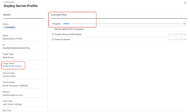
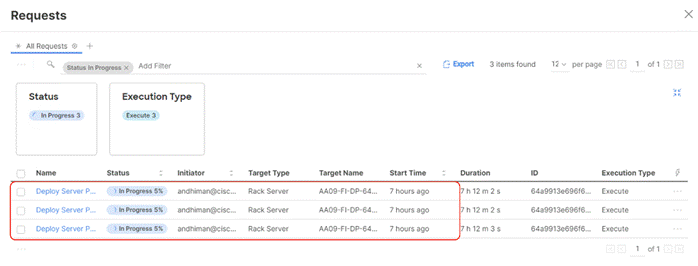
Step 10. Once the Server Profile deployment completes successfully, you can proceed to the Rubrik CDM deployment on the Cisco UCS C-Series nodes.
Step 11. Access KVM with KVM username > kvm-user (RUBRIK) and password > <<as configured in local user policy>>, and make sure the node is accessible.
Step 12. Virtual KVM can be accessed by directly launching from Cisco Intersight (Launch vKVM) or access the node management IP.
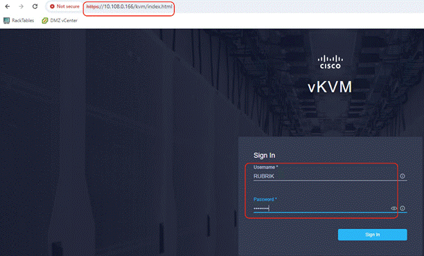
Procedure 1. Install Rubrik CDM through Cisco Intersight OS Installation feature
This procedure details the process to install the Rubrik CDM operating system through the Cisco Intersight OS installation feature.
Note: This feature is only supported with the Intersight Advantage Tier License.
Note: Make sure the certified Rubrik CDM ISO is available from a local repository, for example an HTTPS/NFS/CIFS server. This is a one-time process for each version of the Rubrik CDM ISO.
Step 1. Login to Cisco Intersight and click System.
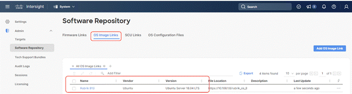
Step 2. Click Software Repository and click the OS Image Links tab.
Step 3. Click Add OS Image Link.
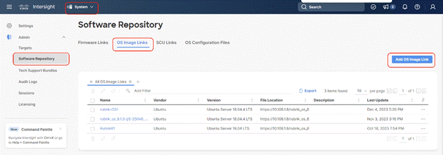
Step 4. Select organization, add the location of the Rubrik CDM ISO (NFS/CIFS or HTTPS server) and click Next.
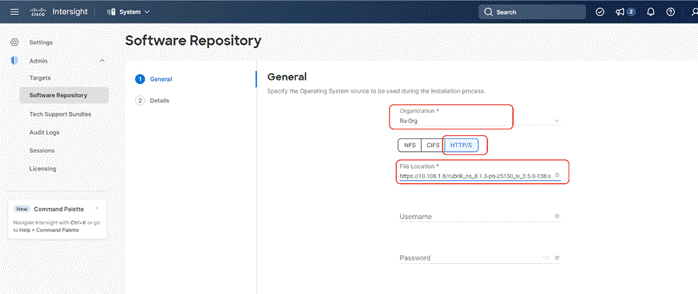
Step 5. Enter a name for the Repository, for the Vendor enter Ubuntu, and for the Version enter Ubuntu 18.04 Click Add.
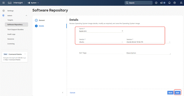
Step 6. Make sure the OS Repository is successfully created in Cisco Intersight.
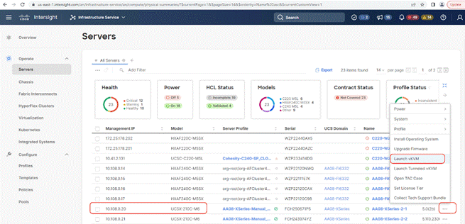
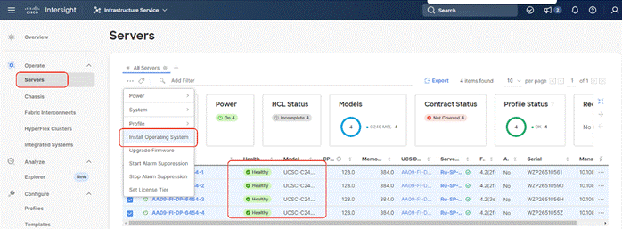
Step 7. From Cisco Intersight, click Infrastructure Service, then click Servers, and select the Cisco UCS C-Series nodes ready for the Rubrik CDM OS installation. Click the … and select Install Operating System. Click the … and select Install Operating System.
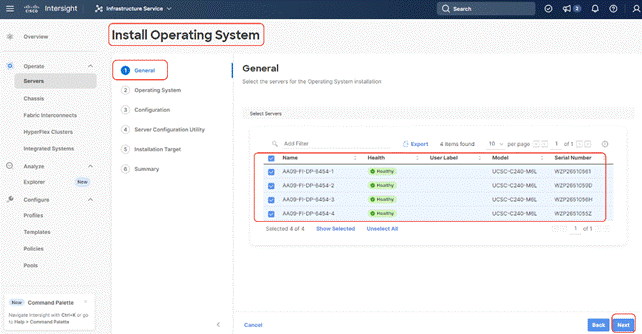
Step 8. In the General tab, ensure the nodes are selected. Click Next.
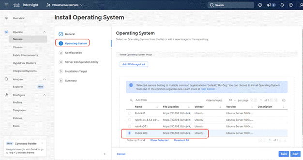
Step 9. Select the Operating System repository which was previously created for Rubrik CDM ISO and click Next.
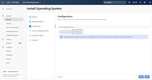
Step 10. From Configuration, click Embedded and click Next (the OS configuration file is already part of Rubrik CDM ISO). Click Next
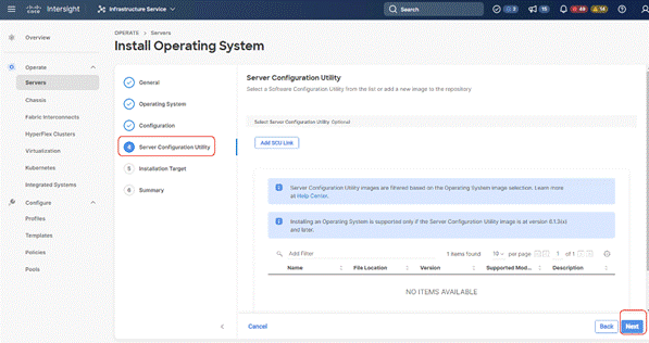
Step 11. Click Next on the Server Configuration Utility (SCU) tab.
Step 12. Click Next from the Installation target. Rubrik CDM ISO automatically identifies the Installation target as the RAID1 virtual drive created across 2x M.2 internal drives configured in the Boot Order Server Policy.
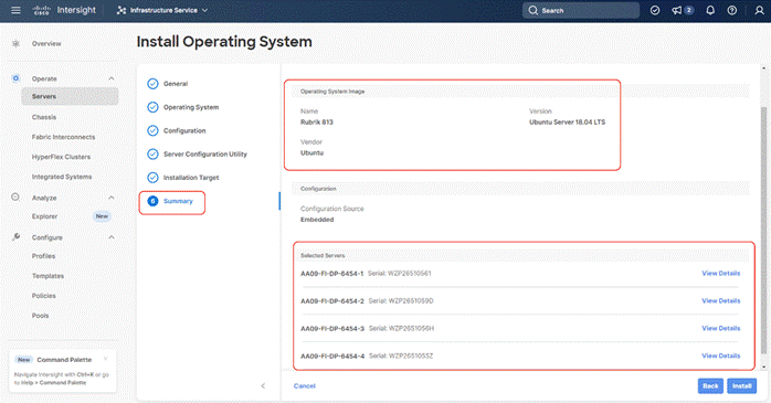
Step 13. Verify the summary and click Install.
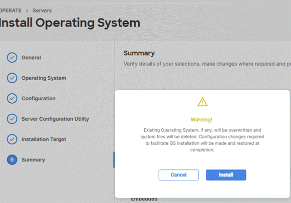
Step 14. Accept the warning for overwriting the existing OS image on the node and click Install.
Step 15. The OS installation for Rubrik on Cisco UCS C-Series nodes require few confirmations. Therefore, you need to open a vKVM window for each of the nodes wherein Rubrik OS is getting installed. The node will reboot for OS installation and the ISO would be automatically mounted.
Step 16. Confirm the Rubrik CDM version.
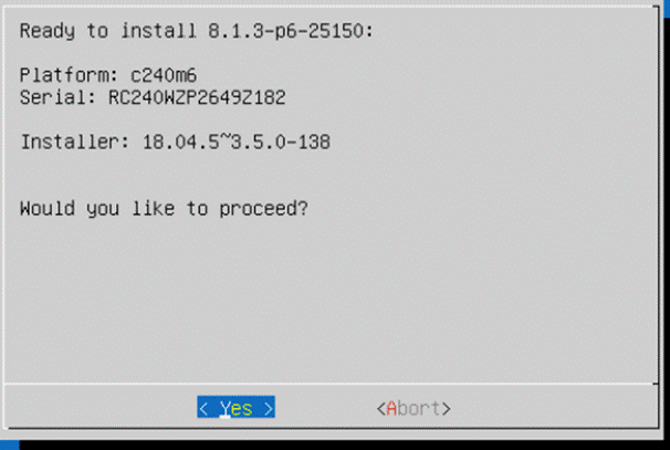
Rubrik Installer will verify the hardware compatibility.

Step 17. When the verification completes, confirm the errors detected. Ignore the NIC count, CPU and SSD model check errors.
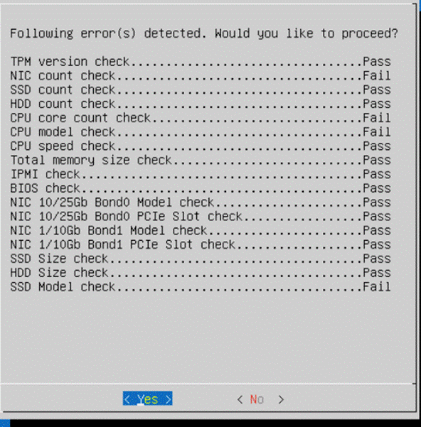
Next, the stage 2 of installation proceeds.

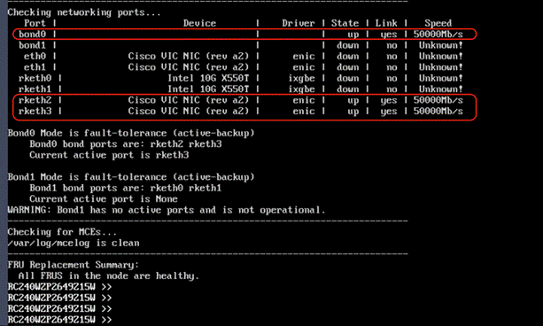
Step 18. When the OS is installed, login to each node (admin/rubrik) and verify the hardware health. Execute ‘cluster hw_health’ on each node to confirm on any hardware issue and the node is healthy.
Note: Ensure the bond0 is created across rketh2 and rketh3 and the network port status is up.
Install OS through Virtual Media
Procedure 1. Install Rubrik CDM OS through Virtual Media
This procedure details the process to install the Rubrik CDM operating system through virtual media. You need to open a virtual KVM session for each node. Virtual KVM session can be accessed through Cisco Intersight or logging into node management IP assigned during Server Profile deployment.
Note: If you are installing the OS through virtual media and it times out, please use a different browser such as Mozilla Firefox.
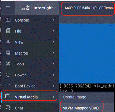
Step 1. Login to virtual KVM, click Virtual Media and click vKVM-Mapped DVD.
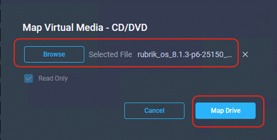
Step 2. Select the Rubrik CDM ISO from your local file system and click Map Drive.
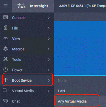
Step 3. Click Boot Device and then select Any Virtual Media as a one time boot device. This ensures the next boot of the node attaches to the ISO mounted on the Virtual Media.
Step 4. Click Power and then click Reset System to reset the power cycle on the node. The Rubrik CDM ISO automatically loads.

Step 5. The entire installation takes about an hour. When all the nodes are installed with Rubrik ISO, you can proceed to configure the Rubrik cluster.
Rubrik Installer will verify the hardware compatibility.
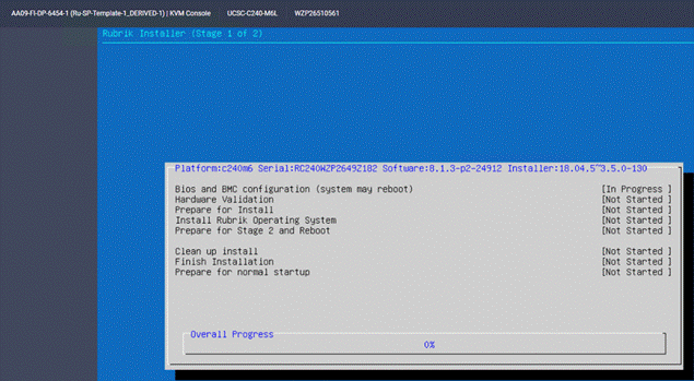
Step 6. When the verification completes, confirm the errors detected. Ignore the NIC count, CPU and SSD model check errors.

Next, the stage 1 of installation will proceed. It may take about 70-80 minutes for completion of stage 1.
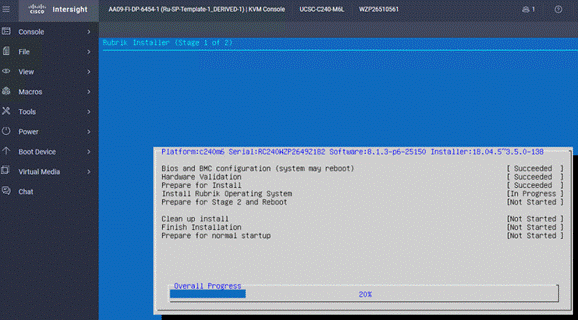
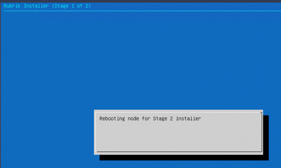
Step 7. When Stage 1 is complete, the installer will reboot the system and proceed to Stage 2.
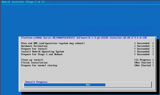
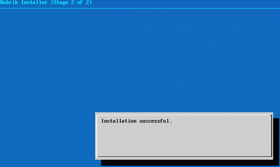
Step 8. When Stage2 is complete and installation succeeds, the node would be ready for normal setup and cluster configuration.
Step 9. Login to each node (admin/rubrik) and verify the hardware health. Execute ‘cluster hw_health’ on each node to confirm on any hardware issue and the node is healthy.
Note: Ensure the bond0 is created across rketh2 and rketh3 and the network port status is up.
Step 10. Repeat this procedure for all Cisco C-Series nodes to be configured for the Rubrik CDM cluster.
Configure Rubrik CDM Cluster
This section elaborates on the configuration of the Rubrik CDM Cluster on Cisco UCS C-Series nodes. The existing deployment is deployed with four (4) Cisco UCS C240 M6 LFF servers.
Note: Make sure the Rubrik CDM ISO is installed on each Cisco C-Series nodes.
Note: The network bonding mode on the Rubrik operating systems with Cisco UCS C-Series servers connected to Cisco UCS Fabric Interconnect, does not support bond mode 4. For reference, go to: https://www.cisco.com/c/en/us/support/docs/servers-unified-computing/ucs-b-series-blade-servers/200519-UCS-B-series-Teaming-Bonding-Options-wi.html)
Note: The following section is for reference; make sure to involve Rubrik support during cluster configuration.
The Rubrik CDM cluster configuration is a three-step process:
● Verify node network status and change node to UCS Managed (UCSM) mode
● Bootstrap cluster
● Register Cluster
Verify node network status and change node to UCS Managed (UCSM) mode.
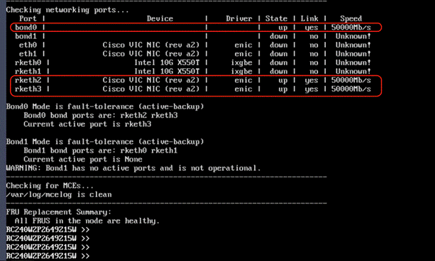
Procedure 1. Verify network active status
In this procedure, administrators should verify the network status of each Cisco UCS C-Series server to be configured as part of Rubrik CDM cluster
Step 1. Ensure Rubrik CDM OS is installed on each node. Login to each node (admin/rubrik) and execute cluster hw_health to verify the node health and network status. The following screenshot displays the output of cluster hw_health. The active network is Bond0 with ports as rketh2 and rketh3 with active-backup fault tolerance mode. These network ports are mapped to vNIC2/vNIC3 created in the LAN Connectivity Policy for Server Profile of Cisco UCS C-Series server. This was created in the Create Server Profile template section.
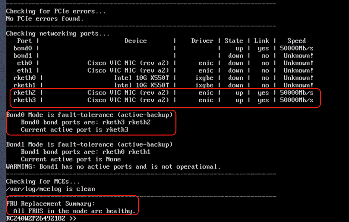
Procedure 2. Convert to UCS Managed node
Step 1. Convert each node in UCS Managed mode. Execute cluster change_cisco_UCS_mode. The following screenshot displays the output. This should be executed across each node which would be configured in Rubrik CDM cluster. This is required for all Cisco UCS C-Series servers configured as Rubrik CDM nodes and connected to Cisco UCS Fabric Interconnect in Intersight Managed Mode (IMM).
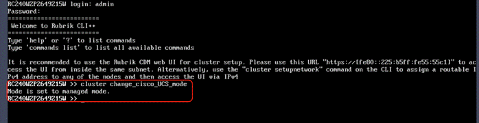
Note: The following section is for reference. Customers and administrators should contact Rubrik support to bootstrap and register Rubrik Cluster.
Note: This section explains the bootstrap process using the CLI method. To bootstrap Rubrik cluster through the UI, please refer to Setting up a Rubrik cluster using the UI in the Rubrik CDM Install and Upgrade Guide.
This section details the cluster bootstrap process. All IP address details should be pre-populated as provided in Table 3 Rubrik Cluster IP Addressing. It is recommended to involve Rubrik support during this process.
Procedure 1. Bootstrap cluster
Step 1. Login to any Rubrik node (admin/rubrik).
Step 2. Execute ‘cluster bootstrap’ Once the general inputs such as cluster name, DNS, NTP are entered, all the nodes pre-installed with Rubrik CDM OS will be discovered.
The following screenshots display the user inputs, marked in RED. All user inputs are detailed Table 3 Rubrik Cluster IP Addressing.
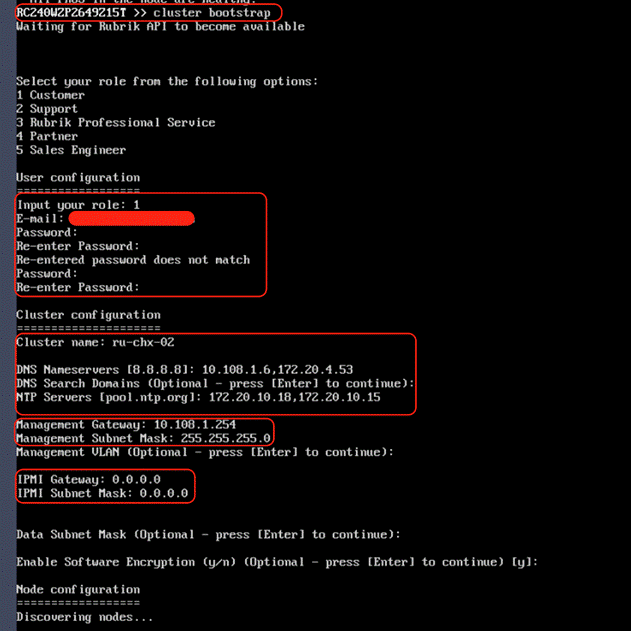
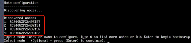
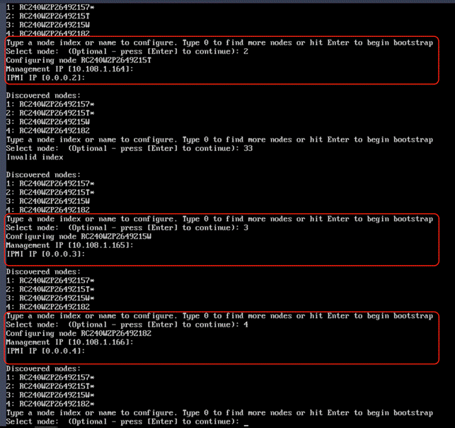
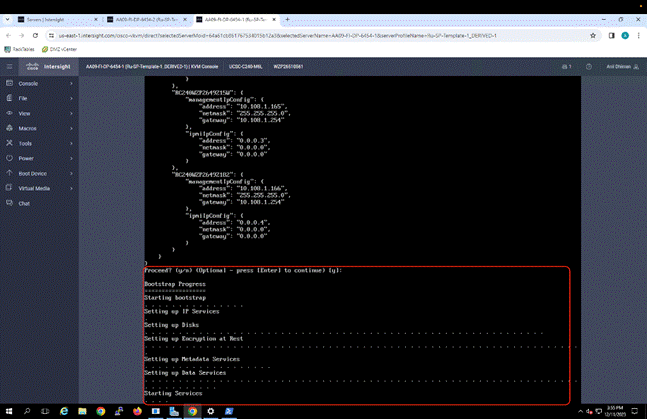
Step 3. When the bootstrap is successful, proceed to registering the cluster to Rubrik Security Cloud (RSC) instance.
Procedure 2. Rubrik Cluster Registration
Note: Ensure you have a Rubrik Security Cloud Instance created for your Rubrik account.
Step 1. Open a browser and login to Rubrik node with the Node OS IP address configured during the bootstrap process.
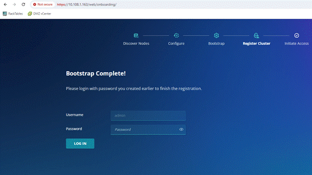
Step 2. Enter the Rubrik Security Cloud URL (RSC) and sign in to Rubrik.
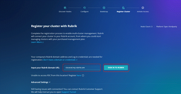
Step 3. Enter your Rubrik Security Cloud instance login and password.
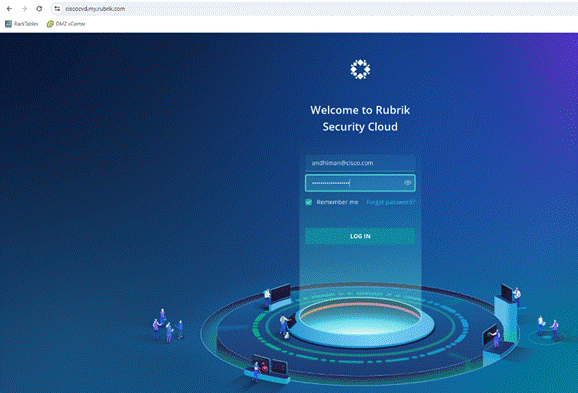
Step 4. Select the SaaS instance service type and confirm the cluster details for registration, click Next.
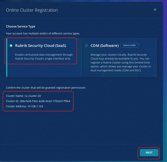
Step 5. Cluster registration may take few minutes, confirm the successful cluster registration to Rubrik Security Cloud instance.
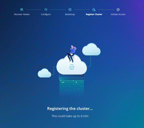
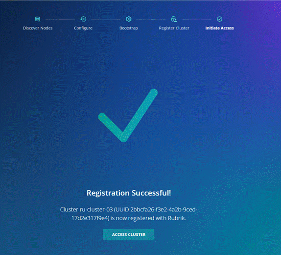
Cluster Expansion and Firmware Upgrades
This chapter contains the following:
● Upgrade Cisco UCS C-Series Node Firmware
Note: Rubrik support should be involved for both Cluster Expansion and Cisco C-Series Firmware Upgrades.
Cluster Expansion is a two-step process:
1. Derive, Deploy Server Profile, and Install Rubrik CDM operating system.
2. Add node through Rubrik management console.
Procedure 1. Derive and Deploy Server Profile to new node
Step 1. Go to https://intersight.com/, click Infrastructure Service and click Server.
Step 2. Verify the Cisco UCS Fabric Interconnect port assigned for the new C-Series node is enabled and has the role as Server. This can be confirmed by viewing the ‘port policy’ assigned to Domain Profile
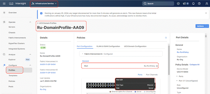
Step 3. Ensure additional Cisco UCS C-Series nodes for Rubrik Cluster is cabled to the Sever Port on Cisco UCS Fabric Interconnect. The following screenshot displays the cabling to Cisco UCS Fabric Interconnect.
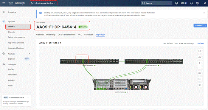
Step 4. Ensure there is an available IP in ‘IP Pool Policy’ assigned to Server Profile Template. This is required for CIMC access to the new Cisco UCS C-Series node.
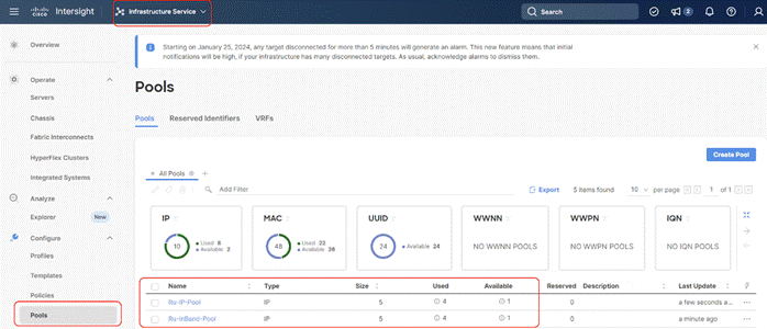
Step 5. Identify the new Cisco UCS C-Series server node, click the ellipses “… “, select Profile and Derive Profile from the template.
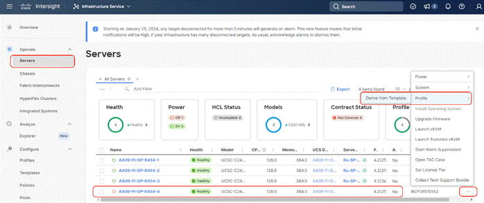
Step 6. The Cisco UCS C-Series node is displayed, click Next.
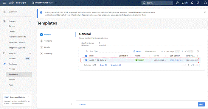
Step 7. Select the Server Profile template created to deploy the Cisco UCS C-Series node for the Rubrik CDM cluster and click Next.
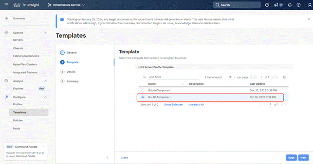
Step 8. Rename the Derive profile and click Next.
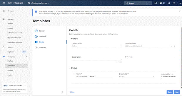
Step 9. Verify the policies and click Derive.
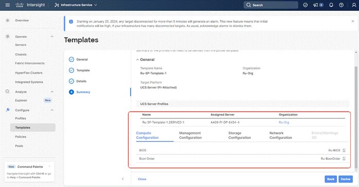
Step 10. When the Sever Profile is derived, go to the Servers tab, identify the Profile displayed as “Not Deployed,” click the ellipses“…” and select Deploy.
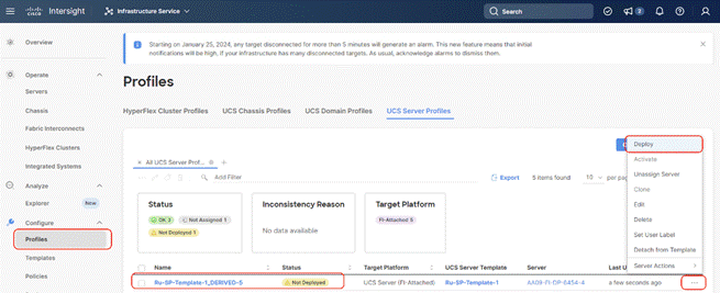
Step 11. On the Deploy Profile confirmation screen, enable Reboot Immediately to Activate and click Deploy.
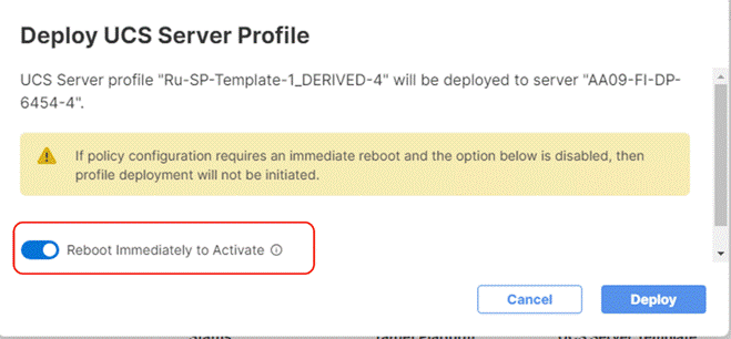
Step 12. Monitor the Sever Profile Deployment task and ensure profile is deployed successfully.
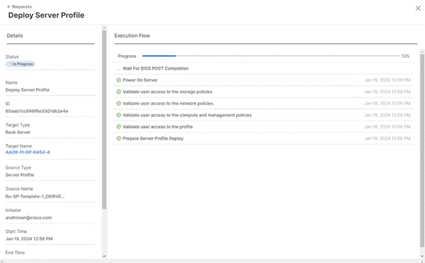
Step 13. When the profile is successfully deployed, install the OS using Cisco Intersight ‘OS installation’ feature or by mounting the Rubrik ISO to KVM console .Once Rubrik OS is installed, verify the node with cluster hw_health.
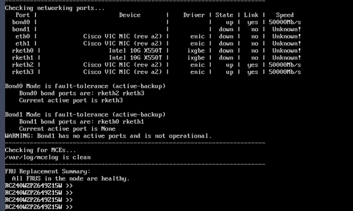
Procedure 2. Add Node through Rubrik Management Console
When the Rubrik CDM operating system is installed and the cluster hw_health is ‘healthy, contact Rubrik support to add the new node to existing cluster.
Note: The Add Node process demonstrates an expansion from three node cluster to four node cluster. Rubrik recommends having a minimum of four node in the cluster. Rubrik support should be involved for both Cluster Expansion and Cisco UCS C-Series Firmware Upgrades.
Note: Ensure the new node has Rubrik OS installed as detailed in the previous section.
Step 1. Ensure the existing cluster is an healthy state.
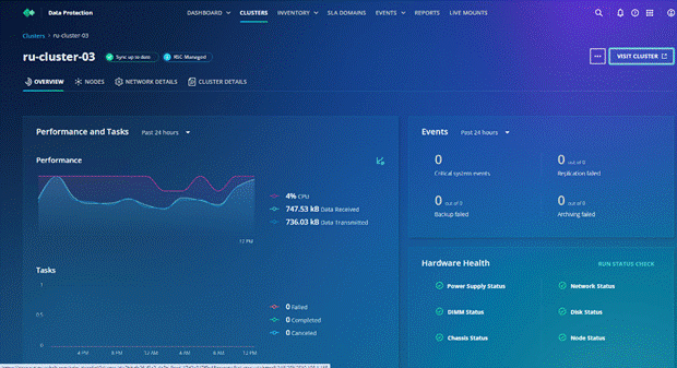
Step 2. Go to the Node tab. It displays a three node cluster. Click Add Node.
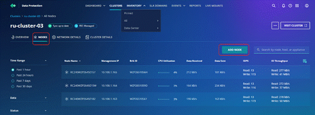
Step 3. Existing cluster automatically identifies the new node. Enter available Node IP address. In present configuration Cisco UCS C-Series nodes are attached to Cisco Fabric Interconnect and do not utilize IPMI configuration. Therefore, the IPMI IPs are configured as 0.0.0.x. Click Next.
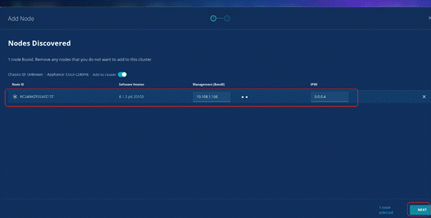
Step 4. Enter the subnet mask and Gateway. In present configuration Cisco UCS C-Series nodes are attached to Cisco Fabric Interconnect and do not utilize IPMI configuration. Therefore, the IPMI Gateway and subnet are 0.0.0.0. The node is registered to the cluster.
Step 5. It takes about 10-15 minutes for the new node to be visible in the cluster. The screenshot below confirms the addition of new node to the existing cluster:
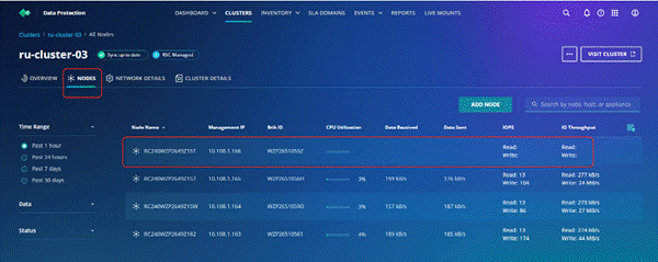
Upgrade Cisco UCS C-Series Node Firmware
Note: With the Intersight SaaS Management platform, the server firmware upgrade does not require you to download any firmware bundles to a local repository. When the suggested firmware upgrade request is issued, it automatically downloads the selected firmware and starts the upgrade process.
For detailed instructions to perform firmware upgrades, see Firmware Management in Intersight
Firmware upgrade of Cisco UCS C-Series nodes connected to Cisco UCS Fabric Interconnect is a two-step process. Administrators should upgrade the Cisco UCS Fabric Interconnect Firmware, thereafter, upgrade the Cisco UCS C-Series node firmware.
Note: Firmware upgrade of Cisco UCS Fabric Interconnect is non-disruptive, but firmware upgrade of Cisco UCS C-Series node is disruptive, administrators should have a maintenance window in which the Rubrik cluster is shutdown. Please contact Rubrik support to provision a maintenance window.
To successfully upgrade the Cisco UCS Fabric Interconnect and IO module firmware, see: https://intersight.com/help/saas/resources/Upgrading_Fabric_Interconnect_Firmware_imm#procedure
Note: During the upgrade of the Intersight Managed Fabric Interconnect, the fabric interconnect traffic evacuation is enabled by default. The fabric interconnect traffic evacuation evacuates all traffic that flows through the fabric interconnect from all servers attached to it, and the traffic will fail over to the peer fabric interconnect for fail over vNICs with no disruptions in the network.
Procedure 1. Upgrade Cisco UCS Fabric Interconnect Firmware
This procedure details the high-level procedure to upgrade firmware of the Cisco UCS Fabric Interconnect in Intersight Managed Mode (IMM). For more details, go to: https://intersight.com/help/saas/resources/Upgrading_Fabric_Interconnect_Firmware_imm#before_you_begin
Step 1. Login to https://Intersight.com, click Infrastructure Service, then click Fabric Interconnects, and select the Fabric Interconnect Pair (IMM). Click the ellipses“…” and select Upgrade Firmware.
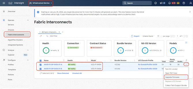
Step 2. Click Start and from Upgrade firmware make sure the UCS Domain Profile is selected and click Next.
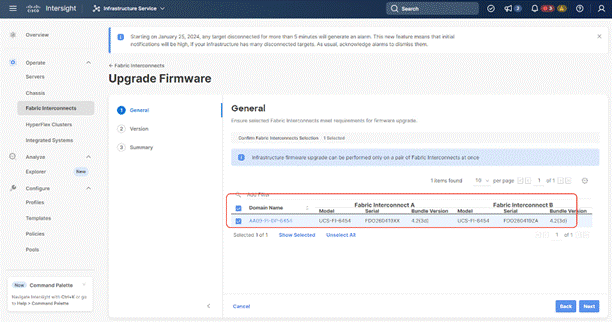
Step 3. Select the recommended Firmware release (currently 4.2(3h)). By default, the upgrade enables the Fabric Interconnect traffic evacuation. Use Advanced Mode to exclude the Fabric Interconnect traffic evacuation.
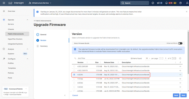
Step 4. On the summary page, confirm the firmware to be upgraded and click Upgrade.
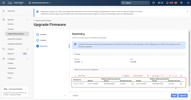
Step 5. Monitor the upgrade process and wait for it to complete.
Step 6. When the Firmware downloads, acknowledge the Fabric Interconnect B upgrade, and click Continue.
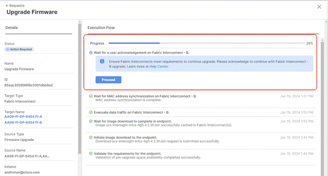
Step 7. When Fabric Interconnect -B is upgraded, acknowledge the Fabric Interconnect – A upgrade.
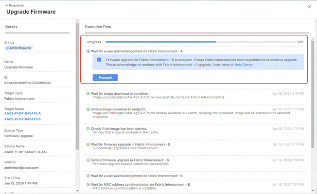
Step 8. Make sure the Firmware upgrade completed successfully.
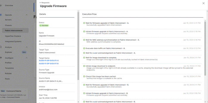
Step 9. Verify the firmware upgraded on the Cisco UCS Fabric Interconnect.
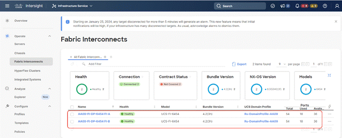
Upgrade Cisco UCS C-Series Node Firmware
This section details the procedure to upgrade the firmware of only Cisco UCS C-Series Rubrik certified nodes. The Rubrik CDM software upgrade is not part of this procedure.
Note: Since the Cisco UCS C-Series firmware upgrade requires a reboot, contact Rubrik support to shut down the cluster during the maintenance window.
This section is utilized in two key circumstances.
● Only the Cisco C-Series node firmware requires an upgrade.
● You are comfortable with having a maintenance window for the Rubrik cluster downtime.
Procedure 1. Upgrade Cisco UCS C-Series Node Firmware
Step 1. Login to https://intersight.com, click Infrastructure Service, then click Servers. Select the Cisco UCS C-Series nodes that are part of the Rubrik cluster. Click the ellipses… icon and select Upgrade Firmware.
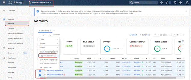
Step 2. Make sure all Cisco UCS C-Series nodes are selected for upgrade. Click Next.
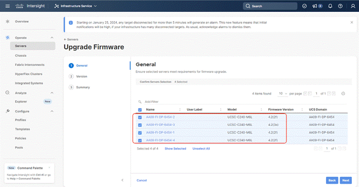
Step 3. Select the recommended Server Firmware version and click Next. At the time of publishing this guide, the suggested firmware was 4.2(3h) If the firmware upgrade does not require drive firmware updates, select Advanced Mode, and check the Exclude Drive option.
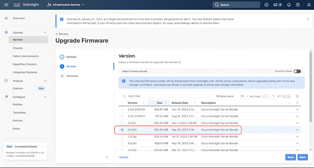
Step 4. Click Upgrade.
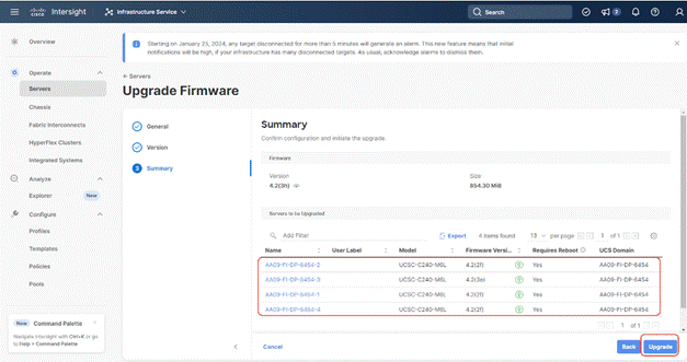
Step 5. Select the Reboot Immediately to Begin Upgrade option. This initiates the firmware upgrade across all Cisco UCS C-Series Rubrik certified nodes.
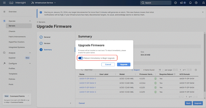
The Firmware image is downloaded to the end point and staged to the respective node:
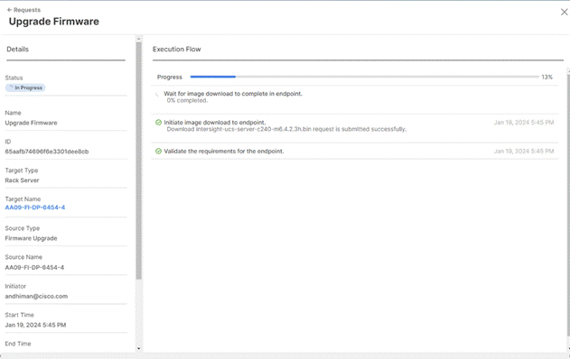
Step 6. Confirm the firmware upgrade across all Cisco UCS C-Series nodes is complete.
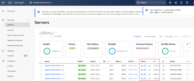
Step 7. Once the firmware across all Cisco UCS C240 LFF nodes are upgraded, restart the Rubrik CDM Cluster.
Rubrik Certified Cisco UCS Nodes
This solution utilizes 4x Cisco UCS C240 M6 LFF nodes configured with Rubrik CDM. Along with this configuration, Cisco and Rubrik have certified solutions with different capacity points available on Cisco UCS C-Series Rack Servers .This allows you to select your configuration based on key characteristics such as:
● Total Capacity
● Cluster Resiliency
● Performance requirements.
Note: Customers should contact Rubrik Sizing Team or Rubrik Sales Specialist for identification of Rubrik Cluster configuration.
Table 12 lists the Rubrik-certified nodes on Cisco UCS Platform.
Table 12. Rubrik Certified Cisco UCS Nodes
| Solution Name |
Cisco UCS Platform |
Capacity per Node |
Caching SSDs/NVMe per Node |
| Rubrik-C240M6 LFF |
Cisco UCS C240 M6 LFF Rack Server with 12 drive options |
48 TB (12x 4TB) |
1.6 TB |
| 96 TB (12x 8TB) |
1.6 TB |
||
| 144 TB (12x 12TB) |
1.6 TB |
||
| 168 TB (12x 14TB) |
1.6 TB |
||
| 192 TB (12x 16TB) |
1.6 TB |
||
| 240 TB (12x 20TB) |
1.6 TB |
||
| 264 TB (12x 22TB) |
1.6 TB |
Anil Dhiman, Technical Leader, Technical Marketing Engineering, UCS Solutions, Compute & Networking Group, Cisco Systems, Inc.
Anil Dhiman has nearly 20 years of experience specializing in data center solutions on Cisco UCS servers, and performance engineering of large-scale enterprise applications. Over the past 12 years, Anil has authored several Cisco Validated Designs for enterprise solutions on Cisco data center technologies. Currently, Anil's focus is on Cisco’s portfolio of hyperconverged infrastructure and data protection solutions.
For their support and contribution to the design, validation, and creation of this Cisco Validated Design, the authors would like to thank:
● Urshila Lohani, Product Manager, Cisco Systems Inc.
● Matt Tangvald, Director of Product Management at Rubrik
● Khush Nezam, Product Manager at Rubrik
● Ken Chao, Manufacturing Operations Support Engineer at Rubrik
● Rui Xiao, Staff Hardware Engineer at Rubrik
● Venkat Nitin P., Sr Software Engineer at Rubrik
● Daryl Stanbery, Senior, Director of Alliances at Rubrik
This appendix is organized into the following sections:
● Appendix A – Bill of Materials
● Appendix B – References Used in this Guide
Appendix A – Bill of Materials
Table 13 provides an example the Bill of Materials used for four (4) node Rubrik CDM cluster deployed on a single Cisco UCS C-Series systems, along with a pair of Cisco Fabric Interconnects, used in the testing and reference design described in this document.
Table 13. Cisco UCS Bill of Materials
| Cisco C-Series estimate (4x C240 M5 LFF nodes) for Rubrik CDM Cluster |
|||
| 1.0 |
UCS-M6-MLB |
UCS M6 RACK, BLADE MLB |
1 |
| 1.1 |
DC-MGT-SAAS |
Cisco Intersight SaaS |
1 |
| 1.1.1 |
DC-MGT-IS-SAAS-AD |
Infrastructure Services SaaS/CVA - Advantage |
4 |
| 1.1.2 |
SVS-DCM-SUPT-BAS |
Basic Support for DCM |
1 |
| 1.1.3 |
DC-MGT-UCSC-1S |
UCS Central Per Server - 1 Server License |
4 |
| 1.2 |
UCSC-C240-M6L |
UCS C240 M6 Rack w/o CPU, mem, drives, 2U w LFF |
4 |
| 1.2.0.1 |
CON-L1NCO-UCSCC2L4 |
CX LEVEL 1 8X7XNCDOSUCS C240 M6 Rack wo CPU mem drives 2 |
4 |
| 1.2.1 |
UCSC-M-V25-04 |
Cisco UCS VIC 1467 quad port 10/25G SFP28 mLOM |
4 |
| 1.2.2 |
CIMC-LATEST |
IMC SW (Recommended) latest release for C-Series Servers. |
4 |
| 1.2.3 |
UCS-M2-240G |
240GB SATA M.2 |
8 |
| 1.2.4 |
UCS-M2-HWRAID |
Cisco Boot optimized M.2 Raid controller |
4 |
| 1.2.5 |
UCSX-TPM-002C |
TPM 2.0, TCG, FIPS140-2, CC EAL4+ Certified, for M6 servers |
4 |
| 1.2.6 |
N20-BKVM |
KVM local IO cable for UCS servers console port |
4 |
| 1.2.7 |
UCSC-RAIL-M6 |
Ball Bearing Rail Kit for C220 & C240 M6 rack servers |
4 |
| 1.2.8 |
UCSC-BBLKD-S2 |
UCS C-Series M5 SFF drive blanking panel |
12 |
| 1.2.9 |
UCS-DIMM-BLK |
UCS DIMM Blanks |
80 |
| 1.2.10 |
UCSC-RIS1B-240M6 |
C240 M6 Riser1B; 2xHDD/SSD; StBkt; (CPU1) |
4 |
| 1.2.11 |
UCSC-RIS2A-240M6 |
C240 / C245 M6 Riser2A; (x8;x16;x8);StBkt; (CPU2) |
4 |
| 1.2.12 |
UCSC-RIS3B-240M6 |
C240 M6 Riser 3B; 2xHDD; StBkt; (CPU2) |
4 |
| 1.2.13 |
UCSC-HSLP-M6 |
Heatsink for 1U/2U LFF/SFF GPU SKU |
8 |
| 1.2.14 |
UCSC-M2EXT-240M6 |
C240M6 / C245M6 2U M.2 Extender board |
4 |
| 1.2.15 |
UCSC-MPSTOM6L-KIT |
C240M6L MID PLANE KIT 4x3.5" HDD |
4 |
| 1.2.16 |
UCS-CPU-I5318N |
Intel 5318N 2.1GHz/150W 24C/36MB DDR4 2667MHz |
8 |
| 1.2.17 |
UCS-MR-X32G2RW |
32GB RDIMM DRx4 3200 (8Gb) |
48 |
| 1.2.18 |
UCSC-SAS-M6HD |
Cisco M6 12G SAS HBA (32 Drives) |
4 |
| 1.2.19 |
UCS-HD12T7KL4KN |
12TB 12G SAS 7.2K RPM LFF HDD (4K) |
48 |
| 1.2.20 |
UCS-NVMEI4-I1600 |
1.6TB 2.5in U.2 Intel P5600 NVMe High Perf Medium Endurance |
4 |
| 1.2.21 |
UCSC-PSU1-1600W |
UCS 1600W AC PSU Platinum (Not EU/UK Lot 9 Compliant) |
8 |
| 1.2.22 |
CAB-C13-C14-2M |
Power Cord Jumper, C13-C14 Connectors, 2 Meter Length |
8 |
| 1.2.23 |
UCS-SID-INFR-OI |
Other Infrastructure |
4 |
| 1.2.24 |
UCS-SID-WKL-OW |
Other Workload |
4 |
| 1.3 |
UCSX-FI-6454-U |
UCS Fabric Interconnect 6454 |
2 |
| 1.3.0.1 |
CON-OSP-UCSXUFI6 |
SNTC-24X7X4OS UCS Fabric Interconnect 6454 |
2 |
| 1.3.1 |
N10-MGT018 |
UCS Manager v4.2 and Intersight Managed Mode v4.2 |
2 |
| 1.3.2 |
UCS-PSU-6332-AC |
UCS 6332/ 6454 Power Supply/100-240VAC |
4 |
| 1.3.3 |
CAB-C13-C14-3M-IN |
Power Cord Jumper, C13-C14 Connectors, 3 Meter Length, India |
4 |
| 1.3.4 |
UCS-ACC-6332 |
UCS 6332/ 6454 Chassis Accessory Kit |
2 |
| 1.3.5 |
UCS-FAN-6332 |
UCS 6332/ 6454 Fan Module |
8 |
Appendix B – References Used in this Guide
Cisco Intersight
https://www.cisco.com/c/en/us/products/servers-unified-computing/intersight/index.html
Cisco Unified Computing System
http://www.cisco.com/en/US/products/ps10265/index.html
Cisco UCS Manager
http://www.cisco.com/en/US/products/ps10281/index.html
Cisco UCS C-Series Rack Servers
https://www.rubrik.com/products/cloud-data-management
For comments and suggestions about this guide and related guides, join the discussion on Cisco Community at https://cs.co/en-cvds.
ALL DESIGNS, SPECIFICATIONS, STATEMENTS, INFORMATION, AND RECOMMENDATIONS (COLLECTIVELY, "DESIGNS") IN THIS MANUAL ARE PRESENTED "AS IS," WITH ALL FAULTS. CISCO AND ITS SUPPLIERS DISCLAIM ALL WARRANTIES, INCLUDING, WITHOUT LIMITATION, THE WARRANTY OF MERCHANTABILITY, FITNESS FOR A PARTICULAR PURPOSE AND NONINFRINGEMENT OR ARISING FROM A COURSE OF DEALING, USAGE, OR TRADE PRACTICE. IN NO EVENT SHALL CISCO OR ITS SUPPLIERS BE LIABLE FOR ANY INDIRECT, SPECIAL, CONSEQUENTIAL, OR INCIDENTAL DAMAGES, INCLUDING, WITHOUT LIMITATION, LOST PROFITS OR LOSS OR DAMAGE TO DATA ARISING OUT OF THE USE OR INABILITY TO USE THE DESIGNS, EVEN IF CISCO OR ITS SUPPLIERS HAVE BEEN ADVISED OF THE POSSIBILITY OF SUCH DAMAGES.
THE DESIGNS ARE SUBJECT TO CHANGE WITHOUT NOTICE. USERS ARE SOLELY RESPONSIBLE FOR THEIR APPLICATION OF THE DESIGNS. THE DESIGNS DO NOT CONSTITUTE THE TECHNICAL OR OTHER PROFESSIONAL ADVICE OF CISCO, ITS SUPPLIERS OR PARTNERS. USERS SHOULD CONSULT THEIR OWN TECHNICAL ADVISORS BEFORE IMPLE-MENTING THE DESIGNS. RESULTS MAY VARY DEPENDING ON FACTORS NOT TESTED BY CISCO.
CCDE, CCENT, Cisco Eos, Cisco Lumin, Cisco Nexus, Cisco StadiumVision, Cisco TelePresence, Cisco WebEx, the Cisco logo, DCE, and Welcome to the Human Network are trademarks; Changing the Way We Work, Live, Play, and Learn and Cisco Store are service marks; and Access Registrar, Aironet, AsyncOS, Bringing the Meeting To You, Catalyst, CCDA, CCDP, CCIE, CCIP, CCNA, CCNP, CCSP, CCVP, Cisco, the Cisco Certified Internetwork Expert logo, Cisco IOS, Cisco Press, Cisco Systems, Cisco Systems Capital, the Cisco Systems logo, Cisco Unified Computing System (Cisco UCS), Cisco UCS B-Series Blade Servers, Cisco UCS C-Series Rack Servers, Cisco UCS S-Series Storage Servers, Cisco UCS Manager, Cisco UCS X-Series, Cisco UCS Management Software, Cisco Unified Fabric, Cisco Application Centric Infrastructure, Cisco Nexus 9000 Series, Cisco Nexus 7000 Series. Cisco Prime Data Center Network Manager, Cisco NX-OS Software, Cisco MDS Series, Cisco Unity, Collaboration Without Limitation, EtherFast, EtherSwitch, Event Center, Fast Step, Follow Me Browsing, FormShare, GigaDrive, HomeLink, Internet Quotient, IOS, iPhone, iQuick Study, LightStream, Linksys, MediaTone, MeetingPlace, MeetingPlace Chime Sound, MGX, Networkers, Networking Academy, Network Registrar, PCNow, PIX, PowerPanels, ProConnect, ScriptShare, SenderBase, SMARTnet, Spectrum Expert, StackWise, The Fastest Way to Increase Your Internet Quotient, TransPath, WebEx, and the WebEx logo are registered trade-marks of Cisco Systems, Inc. and/or its affiliates in the United States and certain other countries. (LDW_P2)
All other trademarks mentioned in this document or website are the property of their respective owners. The use of the word partner does not imply a partnership relationship between Cisco and any other company. (0809R)