- About This Guide
- Before You Begin
- Getting Started with Cisco Vision Dynamic Signage Director Operation
- Working with TV Displays
- Working with Zones, Groups, and Locations
- Working with Content Deployment
- Working with Screen Templates in Cisco Vision Director
- Working with Content in Cisco Vision Director
- Working with Playlists in Cisco Vision Director
- Working with Video Walls
- Working with Event Scripts
- Monitoring Media Player Operation During an Event Using Device Management
- Troubleshooting Event Operations in Cisco Vision Director
- Managing System Services in Cisco Vision Director
- Managing Server Resources in Cisco Vision Director
- Managing Media Player Operation in Cisco Vision Director
- Managing Backups in Cisco Vision Director
- Glossary of Terms
Release 6.3: Cisco Vision Dynamic Signage Director Operations Guide
Bias-Free Language
The documentation set for this product strives to use bias-free language. For the purposes of this documentation set, bias-free is defined as language that does not imply discrimination based on age, disability, gender, racial identity, ethnic identity, sexual orientation, socioeconomic status, and intersectionality. Exceptions may be present in the documentation due to language that is hardcoded in the user interfaces of the product software, language used based on RFP documentation, or language that is used by a referenced third-party product. Learn more about how Cisco is using Inclusive Language.
- Updated:
- August 5, 2020
Chapter: Working with Video Walls
Working with Video Walls
User Role: Administrator / Content Manager
This module provides information about how to design and deploy video walls.
Information About Video Walls
A video wall is a group of displays that show synchronized content and convey a single, much larger screen. Cisco Vision Director supports different video wall design methods depending on the type of media player controlling the video wall.
A common use for video walls is to vary the video wall layout and content over the course of an event.
Content Scaling
Scaling refers to support of two things:
■![]() Showing only a portion of the content per display in a multi-screen video wall.
Showing only a portion of the content per display in a multi-screen video wall.
Multicast Video Scaling
■![]() Supported in Release 5.0 and later releases.
Supported in Release 5.0 and later releases.
■![]() Intended for use in video walls.
Intended for use in video walls.
■![]() Allows scaling of a multicast video region across a video wall display for both portrait and landscape orientation.
Allows scaling of a multicast video region across a video wall display for both portrait and landscape orientation.
IMPORTANT: When using multicast video in a video wall, make sure you use a feed that complies to ISO13818, particularly with respect to program clock reference (PCR). PCR is a value in the transport stream that provides a means for the decoder to lock its video output clock to the video input clock to the encoder that is providing the transport stream. In a video wall, any two DMPs may be up to one frame out of sync.
Video Wall Design Methods
Cisco Vision Director supports the following different video wall design methods, depending on your media player model:
■![]() DMP-to-DMP content synchronization
DMP-to-DMP content synchronization
■![]() Zone-based video wall synchronization
Zone-based video wall synchronization
Note : While TV-based tile matrix video walls can be used for the SV-4K, the best practice for full HD resolution is to use either DMP-to-DMP content synchronization or zone-based video wall synchronization methods.
TV-Based Tile Matrix
All media players support TV-based tile matrix video walls.
A TV-based tile matrix video wall requires the use of TVs that have built-in tile matrix capabilities, where video input from one player is stretched across all displays. Due to this stretching, the resolution is proportionately reduced.
The tile matrix functionality is configured using RS-232 commands that specify the overall "x" and "y" dimensions of the matrix, as well as each TV’s position in the video wall.
DMP-to-DMP Content Synchronization
The DMP-to-DMP Content Synchronization feature for the digital media player synchronizes content rendering of playlist items on the displays. For video files, synchronization can still be off by a few milliseconds. The DMP will resync every second.
This synchronization includes transitioning from one item to the next (such as for still images), and more accurate playback and rendering of local video content. For local video, this serves as the foundation for implementing video ribbon boards and video walls. This requires cabling of a single media player per display.
Note : Widgets, external URLs, and multicast video tuning synchronization are outside the scope of this feature.
Cisco Vision Director Release 4.0 and later supports enhanced content synchronization methods for the DMPs, with close synchronization of playlist item transition using the Precision Time Protocol (PTP).
Zone-Based Video Wall Synchronization
Zone-based video wall synchronization is an alternative form of synchronization available for devices participating in a video wall.
The primary benefit of this form of synchronization is that if any device that is not the leader in the video wall reboots, it will “catch up” to play whatever content item that the rest of the video wall is currently playing. This form of synchronization is recommended for dedicated video walls that are running video content longer than 15 minutes.
If a device reboots in a video wall that is not using zone-based video wall synchronization (using normal DMP-to-DMP synchronization), the tradeoff is that the rebooting device synchronizes with the rest of the video wall at the next content item in the playlist, or at replay of a single-item playlist.
Summary of Video Wall Synchronization Methods for the DMPs
Table 1 provides a comparison of the configuration guidelines and behavior for device reboot in a DMP video wall for the two content synchronization methods.
Note : Both content synchronization methods use single device cabling per TV display. See Dynamic Video Wall Sizing.
Constant Bit Rate (CBR) is required for best performance.
Note: The unicasting feature has not been tested in a video wall configuration.
Table 1 DMP Video Wall Synchronization Summary 10
Dynamic Video Wall Sizing
To synchronize local videos across multiple DMPs, set the Use as Video Wall to “true.” See Figure 1. This is not for multicast streaming. This tells the system to treat the DMPs in a zone or group to be part of a video wall or not. This means now you *can* change a video wall size from one state to another.
1.![]() Go to Configuration > Groups & Zones (Figure 1).
Go to Configuration > Groups & Zones (Figure 1).
2.![]() Click the Group <-> Zone tab.
Click the Group <-> Zone tab.
Figure 1 Enable Dynamic Video Wall Sizing

5.![]() Click the Edit icon (pencil). The Edit Zone dialog box appears (Figure 2).
Click the Edit icon (pencil). The Edit Zone dialog box appears (Figure 2).

6.![]() Click the Use as Video wall check box.
Click the Use as Video wall check box.
Two good reasons to set a “Sync Manager”:
1.![]() When Use as Video Wall is set to “ true,” the system enables a “leader” DMP which maintains very tight synchronization between all the DMPs in the video wall. The leader DMP controls precisely where all DMPs play content, regardless of failure.
When Use as Video Wall is set to “ true,” the system enables a “leader” DMP which maintains very tight synchronization between all the DMPs in the video wall. The leader DMP controls precisely where all DMPs play content, regardless of failure.
2.![]() If one of the DMPs has to reboot or gets restarted, without a “Sync Manager” enabled, that DMP would restart the video file and start replaying the content from the beginning, and be unable to jump to the exact location of the other DMPs. This throws-off the continuity of the video wall.
If one of the DMPs has to reboot or gets restarted, without a “Sync Manager” enabled, that DMP would restart the video file and start replaying the content from the beginning, and be unable to jump to the exact location of the other DMPs. This throws-off the continuity of the video wall.
Video Wall Cabling
A video wall can be connected in the following ways:
■![]() Daisy-Chained TV Displays for TV-Based Tile Matrix Video Walls
Daisy-Chained TV Displays for TV-Based Tile Matrix Video Walls
Daisy-Chained TV Displays for TV-Based Tile Matrix Video Walls
This cabling method is supported by all media players and uses the native tile matrix capabilities of the TV displays in the video wall.
In this cabling method, the TV displays in the video wall group are connected together using the DVI In/Out ports. One media player is connected to a single TV in the group using HDMI and RS-232 connections.
Figure 3 shows an example of a 2x2 tile matrix configuration with 4 displays daisy-chained in a group with control of the group by a single digital media player. In this example, notice that all displays are using 1920x1080 format.
IMPORTANT: For the 2x1 portion of the video wall, the DMP crops a 1920x1080 canvas to the 960x1080 signal resolution rather than shrinks it. Therefore, you must specify the correct template to match your signal resolution and your content must match the template. For more information, see Understanding Content and TV Resolution.
Figure 3 Daisy-Chained 2x2 Tile Matrix Example with the DMP

DMP Connection Per TV Display in a Video Wall
The DMPs support display of synchronized local content (video or images) in your video wall.
In this cabling method for local video synchronization, a single media player is connected to each TV display in the video wall using the HDMI Out and RS-232 connections ( Figure 4). It can be used for video walls playing local video that do not rely on the tile matrix capabilities of the TV.
With this architecture, you can develop content at 3840x2160 resolution. Then, divide your video into four 1920x1080 pieces for synchronized playback. This method will use the maximum resolution for each display giving you the highest possible quality for your presentation.
Figure 4 Video Wall with Single SV-4K Per TV Display

This cabling method also is required for zone-based synchronization, which is recommended to achieve enhanced functionality for dedicated video walls running videos with a duration greater than 15 minutes.
Video Wall Design Examples
This section provides examples of some of the more common and currently deployed video wall designs in Cisco Vision venues.
TIP: Be sure to consult with the video wall experts from the Cisco Creative Services team for any of your video wall ideas, including non-standard configurations. This team can help you with ideas, best practices, and wiring diagrams to ensure a successful deployment.
2x3 TV-Based Tile Matrix Video Wall Example
Figure 5 shows a video wall commonly used in a concourse area, with a larger game feed for groups of patrons to watch, along with rotating sponsor content displayed beside the game.
Figure 5 2x3 Video Wall Content Example

A 2x3 video wall is the most common video wall that Cisco recommends because in the left 2x2 group of displays, the game feed maintains the proper 16:9 aspect ratio of the HD game feed. This 2x3 TV/display grid can be implemented in Cisco Vision Director as two types of video walls: a 2x2 and a 2x1.
The right 2x1 group of displays can work independently from the game feed and show sponsor, social, or other content throughout the game. The user also can change the type of content that plays during the game. For example, during half-time or period break, when there is no game feed, the user can switch the 2x2 to play full screen sponsor content, while changing the 2x1 to show upcoming events or team branded content so that there are not any sponsor conflicts.
Figure 6 shows the cabling for the 2x3 video wall example, where two Cisco DMPs are used to break the wall into different display areas.
The first DMP provides the 2x2 game feed and the second DMP provides the 2x1 sponsor ads.
Note : This cabling design is not the recommended design for the digital media players. Instead, a single player per display is preferred for video walls. For more information, see the DMP Connection Per TV Display in a Video Wall. In addition, use of any resolution other than 1920x1080 is not technically supported on the DMPs (although it might work).
Figure 6 2x3 Video Wall Cabling Example Using TV Tile Matrix Functionality

These dedicated DMPs provide the video signal for the group of TVs that the DMP is connected to through the daisy-chain. Depending on the screen manufacturer, the RS-232 connections can also be daisy-chained if this feature is available.
When operating in tile matrix mode, the TVs are fed the same video signal. Based on the TV’s tile matrix configuration, the TV knows to first scale input video to the size of the configured x,y dimensions, and then to display its “piece” of the overall display based on its configured position within the matrix.
Note : If you want to show multiple types of content, such as four different channels on each of the screens, connect a DMP behind each TV. Please see Best Practices for Video Walls for further clarification and limitations.
Other Video Wall Configurations
While the 2x3 video wall is the most commonly used video wall configuration, using the information and concepts from Figure 6, you can create any number of different video wall configurations (Figure 7, Figure 8, and Figure 9). By arranging the physical layout of the displays, you can create a display that appears to be much larger. At center of Figure 7 is a 2 X 2 video wall.
IMPORTANT: These video wall examples require a different number of DMPs and cabling than the 2x3 video wall.
Figure 7 2 X 2 Video Wall in the Middle, Example

Figure 8 3x3 Video Wall in the Middle, Example

Figure 9 Two, 2x2 Video Walls in the Middle, Example

Best Practices for Video Walls
When implementing video walls, consider the following best practices:
■![]() Use the same media player model (such as all CV-HD2, or all CV-UHD2 media players) throughout the video wall.
Use the same media player model (such as all CV-HD2, or all CV-UHD2 media players) throughout the video wall.
■![]() Use the same TV model throughout the video wall with a uniform bezel size (ultra narrow bezel strongly recommended).
Use the same TV model throughout the video wall with a uniform bezel size (ultra narrow bezel strongly recommended).
Note : TV screens with an ultra narrow bezel help ensure the best viewing experience without important text or data being cut off.
IMPORTANT: For multicast video, specifically, keep in mind the bezels in the monitors and the motion on the video to be displayed in the wall. Fast motion video, coupled with up-to-1 frame out of sync, in a wall larger than 3x3 magnifies the out-of-sync issue. Choose the right video wall strategy for your use case.
■![]() While using multicast videos for both video regions is supported, it is recommended to use a combination of multicast and locally-stored videos for the video regions (or local video for both video regions).
While using multicast videos for both video regions is supported, it is recommended to use a combination of multicast and locally-stored videos for the video regions (or local video for both video regions).
■![]() Create video to be the same size as the video region where it will be rendered. This avoids any unnecessary video scaling.
Create video to be the same size as the video region where it will be rendered. This avoids any unnecessary video scaling.
■![]() Use consistent video aspect ratio, and design video regions so that they are consistent with the aspect ratio of video content.
Use consistent video aspect ratio, and design video regions so that they are consistent with the aspect ratio of video content.
■![]() Use constant bit rate (CBR) for local video files for best performance in video walls.
Use constant bit rate (CBR) for local video files for best performance in video walls.
Restrictions for Video Walls
Before you create video walls, consider the following restrictions:
■![]() In Release 4.1 and earlier releases, multicast video is not supported for a multi-screen video wall. For example, the DMPs cannot stretch multicast content across four displays to convey a single image.
In Release 4.1 and earlier releases, multicast video is not supported for a multi-screen video wall. For example, the DMPs cannot stretch multicast content across four displays to convey a single image.
Note : Support for multicast video scaling in a video wall was introduced in Release 5.0.
■![]() All screens in the video wall should use 1920x1080 format.
All screens in the video wall should use 1920x1080 format.
■![]() Widgets, external URLs, and multicast video tuning synchronization are not supported by the DMP-to-DMP content synchronization feature for the digital media players.
Widgets, external URLs, and multicast video tuning synchronization are not supported by the DMP-to-DMP content synchronization feature for the digital media players.
■![]() When using zone-based content synchronization for video walls, one device controls synchronization. If that device stops showing video, then all displays in the video wall stop showing content.
When using zone-based content synchronization for video walls, one device controls synchronization. If that device stops showing video, then all displays in the video wall stop showing content.
■![]() Multicast stream must be CBR and have PCR jitter within MPEG spec of +/-500 ns.
Multicast stream must be CBR and have PCR jitter within MPEG spec of +/-500 ns.
How to Configure Video Walls with the Digital Media Players
■![]() For streaming local content video files, local file sync can be within 1 frame of other DMPs.
For streaming local content video files, local file sync can be within 1 frame of other DMPs.
■![]() For multicast video streaming, the video can be within 1 frame. For successful display, the multicast stream feed must be CBR and have PCR jitter within MPEG spec of +/-500 ns.
For multicast video streaming, the video can be within 1 frame. For successful display, the multicast stream feed must be CBR and have PCR jitter within MPEG spec of +/-500 ns.
■![]() The network quality of service (QoS) must be within specifications. See Cisco Vision Network, Server, and Video Headend Requirements Guide.
The network quality of service (QoS) must be within specifications. See Cisco Vision Network, Server, and Video Headend Requirements Guide.
■![]() The more you stretch / scale up content, the more noticeable the slightest sync differential is. Please consult Cisco Content Services for your specific video wall configuration.
The more you stretch / scale up content, the more noticeable the slightest sync differential is. Please consult Cisco Content Services for your specific video wall configuration.
This section includes the following topics:
■![]() Prerequisites for Video Walls
Prerequisites for Video Walls
■![]() Workflow Summary to Configure Video Walls
Workflow Summary to Configure Video Walls
■![]() Configuring Zone-Based Video Wall Synchronization for the DMPs
Configuring Zone-Based Video Wall Synchronization for the DMPs
Prerequisites for Video Walls
Before you deploy video walls and create the content for them, be sure that the following conditions are met:
■![]() Beginning in Release 5.0, scaling of multicast video is supported for a video wall in both portrait and landscape orientation. See Content Scaling.
Beginning in Release 5.0, scaling of multicast video is supported for a video wall in both portrait and landscape orientation. See Content Scaling.
■![]() Generally speaking, stretching a piece of content across multiple screens is not supported for local content.
Generally speaking, stretching a piece of content across multiple screens is not supported for local content.
–![]() Local video or image content to be played in a video wall first must be created in the overall format of the video wall to be supported, and then edited into separate 1920x1080 files that contain the segment of content to be shown on each display.
Local video or image content to be played in a video wall first must be created in the overall format of the video wall to be supported, and then edited into separate 1920x1080 files that contain the segment of content to be shown on each display.
–![]() For example, in a 2x2 SV-4K video wall (4 screens), the original content should be in 3840x2160 format (that is, 2 times 1920x1080). Then, it should be broken into four individual files of 1920x1080 format to show the appropriate portion of the content for the 4-screen display.
For example, in a 2x2 SV-4K video wall (4 screens), the original content should be in 3840x2160 format (that is, 2 times 1920x1080). Then, it should be broken into four individual files of 1920x1080 format to show the appropriate portion of the content for the 4-screen display.
■![]() The DMPs in the video wall must be on the same virtual local area network (VLAN) and use the same access switch.
The DMPs in the video wall must be on the same virtual local area network (VLAN) and use the same access switch.
–![]() Each digital media player must be in its own group.
Each digital media player must be in its own group.
–![]() For each region, the playlists must have the same number of items, type of item, and duration of each item, or have no playlist at all in the region (empty).
For each region, the playlists must have the same number of items, type of item, and duration of each item, or have no playlist at all in the region (empty).
Table 2 shows an example of playlist content for a 2x2 SV-4K video wall with a mix of local video and image content. Notice that all first items in each of the four playlists are of the same type (PNGs), with the same duration, but the content itself is not the same. Likewise, the second item in each playlist is video content with the same duration, but different files.
Table 2 2x2 Video Wall Playlist Example for the SV-4K
–![]() Trim local video item duration to boundaries in seconds and not fractions of seconds.
Trim local video item duration to boundaries in seconds and not fractions of seconds.
IMPORTANT : If your imported video content duration is in fractions of seconds, then the Content screen shows the actual item duration for the video. However, the system actually rounds that content duration for the playlist to even time boundaries (in seconds). Also, if you manually change the item duration within the Cisco Vision Director UI, the content playback will be truncated.
■![]() For zone-based video wall synchronization:
For zone-based video wall synchronization:
–![]() Each media player must be in its own group.
Each media player must be in its own group.
–![]() Collectively, the groups that are part of the video wall are placed in a zone.
Collectively, the groups that are part of the video wall are placed in a zone.
–![]() The “Use as Video Wall” checkbox is selected when you create the zone for the DMP groups.
The “Use as Video Wall” checkbox is selected when you create the zone for the DMP groups.
Workflow Summary to Configure Video Walls
Table 3 provides a summary of the tasks and guidelines for you to complete when configuring a video wall using digital media players.
Table 3 DMP Video Wall Task Workflow
|
|
|
|
|---|---|---|
|
|
|
|
|
|
|
|
|
|
|
|
|
|
|
|
|
|
|
|
|
|
|
|
|
|
|
|
|
|
|
|
|
|
|
|
|
|
|
|
Configuring Zone-Based Video Wall Synchronization for the DMPs
Zone-based video wall synchronization provides enhanced recovery for video walls if a DMP reboots during the running of a playlist. It is intended for dedicated video walls running video content of longer duration (> 15 minutes).
Enabling System Support for Zone-Based Video Wall Synchronization for the DMPs
To enable system support for zone-based video wall synchronization:
1.![]() Click Configuration > System Configuration > Global DMP Settings > Default - Audio/Video/Closed Caption.
Click Configuration > System Configuration > Global DMP Settings > Default - Audio/Video/Closed Caption.
2.![]() In the Configuration Property box, locate the Zone Based Video Wall Synchronization property.
In the Configuration Property box, locate the Zone Based Video Wall Synchronization property.
3.![]() Click Edit. The Edit - Configuration dialog box appears.
Click Edit. The Edit - Configuration dialog box appears.
4.![]() In the Value field, type true (Figure 10).
In the Value field, type true (Figure 10).
Figure 10 Zone-Based Video Wall Synchronization

To verify the multicast configuration for zone-based video wall synchronization:
1.![]() Click Configuration > System Configuration > Global DMP Settings > Networking.
Click Configuration > System Configuration > Global DMP Settings > Networking.
2.![]() Verify that the default values for the following properties are compatible with your network, and change as required:
Verify that the default values for the following properties are compatible with your network, and change as required:
Content sync multicast address—239.193.0.253
Content sync multicast port—50001
Configuring Groups and Zones for Zone-Based Video Wall Synchronization for the DMPs
Video Offset Control for Video Walls
The video offset controls provide you with a more granular method of controlling the playout rate of content on a specific TV which is part of a video wall by compensating for the TV painting/scanning process. The function relates to the TV refresh rate and the row a specific TV is in, as part of a video wall.
The function must be applied to a “group” of DMPs that are typically on the same row of the video wall. To be clear, the “video wall” is a set of displays that, collectively, show one piece of content, that are all synchronized. A matrix of displays can be composed of multiple (Cisco Vision Director) video walls. The entire matrix of displays is also sometimes referred to as a video wall, but not all of the content in this case, is all synchronized.
Prior to setting the value for the video offset control, understand the refresh rate of your TVs which are part of the video wall. Figure 11 shows an example of the refresh rate for a sample TV.
Figure 11 Sample of TV Display Refresh Rate

To improve the video wall synchronicity and help compensate for the TV refresh rates, use this calculation.
(Row – 1) X (1 / Rr) X 1000 = Z ms
Row = Row of TVs in the video wall
Z = Video offset value in milliseconds (ms)
Figure 12 shows a video wall example creating the look of a 3 X 3 video wall using three separate video walls.
Figure 12 Video Wall Example, Using 3 Walls

Here’s how the video offset would look for Zone 3 (Figure 13).
Figure 13 Zone 3 Video Offset Values

To create or edit a video wall:
1.![]() Go to Configuration > Groups & Zones.
Go to Configuration > Groups & Zones.
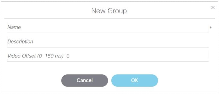
3.![]() Click + Add or Edit. The dialog box appears (Figure 14).
Click + Add or Edit. The dialog box appears (Figure 14).
Figure 14 New Group or Edit Group Dialog Boxes
2X2 Video Wall
■![]() Total wall resolution: 3840 X 2160
Total wall resolution: 3840 X 2160
■![]() Each TV videomode: 1920 X 1080 X 60p
Each TV videomode: 1920 X 1080 X 60p
To configure zone-based video wall synchronization for the DMPs :
1.![]() Go to Configuration > Groups & Zones > Groups<->Zone tab > Groups tab.
Go to Configuration > Groups & Zones > Groups<->Zone tab > Groups tab.
2.![]() Create a new group for each media player that is part of the video wall.
Create a new group for each media player that is part of the video wall.
3.![]() Add only one DMP location per group.
Add only one DMP location per group.
4.![]() Create a new zone and select the Use as Video Wall checkbox (Figure 15).
Create a new zone and select the Use as Video Wall checkbox (Figure 15).

5.![]() Add all DMP groups in the video wall to the zone.
Add all DMP groups in the video wall to the zone.
Note : Synchronization applies only to video and still images. Synchronization cannot be guaranteed for other content such as tickers, external URLs, or widgets.
All DMPs in the video wall must be using FW 8.1.69.
The video offset value ONLY applies to a video wall formation if it has rows (e.g. 2x2, 3x3, 4x1, etc.)—vertical formations of TVs) since the function works on the playout rate of content from top to bottom. It does NOT apply to a video ribbon board formation (e.g. 1x4)—horizontal formations of TVs.
The function primarily benefits file-based video content. It will also provide enhanced synchronization benefits for multicast-based video content. Additional features will be available in firmware 8.2 that will specifically address multicast streaming.
The Video offset control does not rely on the frame rate of the content, be it video file based, or stream based.
Zone based video wall synchronizations should be setup as per normal.
If the video wall is used in an individual TV formation (i.e. video wall formation is NOT used), then the user may experience a very slight delay in content playout when looking at all the screens IF the content is exactly the same. This is because each TV is playing out content with an offset value and it may be perceived that Row 1 is playing out content faster than Row 2 and 3, respectively. Its also important to understand that this formation is not a commonly deployed setup.
 Feedback