Designing Large Scale Service Provider Dial Networks with OSPF
Available Languages
Contents
Introduction
To design a dial network is a challenging task for Internet Service Providers (ISPs). Each ISP uses a unique method to design dial networks. However, all ISPs share the same areas of concern when they design dial networks, as listed here:
-
How must the pool routes be propagated into the ISP core?
-
What routing protocol must be used to carry those routes into the core?
-
Should those dialup routes be summarized before sending into the core?
-
What must be taken into account when the pools are distributed?
-
What happens if the pools are static?
This document addresses most of the questions above and deals with the design practices of using the Interior Gateway Protocol (IGP) Open Shortest Path First (OSPF) in an ISP dial environment. OSPF is often used in the core network of ISPs. In this document, we avoid introducing a separate protocol for carrying the dial pool routes—we use OSPF to propagate the dial pool routes into the core.
Network Topology
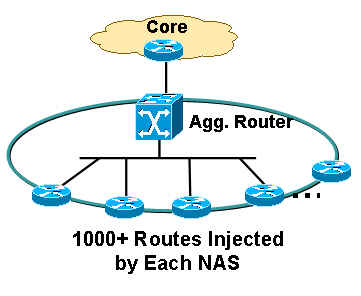
The topology shown here is a typical ISP dial network topology. ISPs that provide dialup services usually have a series of Network Access Servers (NAS) which are typically AS5300 or AS5800. The servers are responsible for the provision of the IP address to all users who dial into the ISP and want to use Internet services. The NAS servers are then connected to an aggregation device, which is typically a Cisco 6500 router. The 6500 router propagates the dialup routes into the core, which allows the core routers to provide Internet services to end users. Figure 1 shows a typical point of presence (POP) scenario.
Figure 1 – A Typical POP Scenario 
ISP Dialup Pools
An ISP typically deals with two types of pool IP addresses:
-
Static
-
Central
Static Pool
With static pools, ISPs have a specific set of IP addresses dedicated to each NAS server. A user who encounters a NAS receives one of the dedicated IP addresses from the pool. For example, if NAS1 static pool address range is 192.168.0.0/22, there are approximately 1023 IP addresses. A user who encounters NAS1 receives one of the addresses in the range from 192.168.0.0 to 192.168.3.254.
Central Pool
With central pools, ISPs have a larger range of IP addresses distributed throughout all the NASs in a single POP. A user who encounters a NAS receives an IP address from the central pool, which is very large range. For example, if the central pool address range is 192.168.0.0/18, and they are distributed between 14 NAS servers, there are approximately 14000 IP addresses.
Dialup Design with a Static Pool
Static pools are easier to manage from a routing perspective. When a static pool is defined on a NAS, the pool needs to be propagated to the core for routing purposes.
Use these methods to propagate dialup routes from a NAS:
-
Create a static route to the pool IP address range, pointing to null 0, with the pool address redistributed on the NAS.
-
Assign the pool IP address on a loopback, on NAS with the OSPF point-to-point network type, including loopback in an OSPF area.
-
Configure a static route on an area border router (ABR) for the pool IP address pointing toward NAS autonomous system boundary router (ASBR)—this is a preferred method because summarization can be performed at the ABR.
Create a Static Route to the Pool Address Range Pointing to null 0
If you use this method, a static route must be created for each NAS. That static route must cover the exact static pool range address pointing to null 0. For example, if the static pool address is 192.168.0.0/22, the static route configuration on NAS is:
NAS1(config)# ip route 192.168.0.0 255.255.252.0 null0
NAS1(config)# router ospf 1
NAS1(config-router)# redistribute static subnets
NAS1(config-router)# end
The pool address is redistributed into OSPF, which propagates this information into the core in the type 5 external link-state advertisement (LSA) form.
Assign the Pool Address on a Loopback on a NAS with the OSPF Point-to-Point Network Type
If you use this method, no static route is required. The pool address is assigned as a subnet on a loopback interface. The default network type on the loopback interface is LOOPBACK, which, according to RFC 2328 ![]() must be advertised in OSPF as /32—this is why you must change the network type on the loopback to point-to-point. The point-to-point network type forces OSPF to advertise the subnet address of the loopback, which in this case is 192.168.0.0/22. Here is the configuration:
must be advertised in OSPF as /32—this is why you must change the network type on the loopback to point-to-point. The point-to-point network type forces OSPF to advertise the subnet address of the loopback, which in this case is 192.168.0.0/22. Here is the configuration:
NAS1(config)# interface loopback 1
NAS1(config-if)# ip addreess 192.168.0.1 255.255.252.0
NAS1(config-if)# ip ospf network-type point-to-point
NAS1(config-if)# router ospf 1
NAS1(config-router)# network 192.168.0.0 0.0.3.255 area 1
NAS1(config-router)# end
This configuration creates a router stub link in the router LSA and is propagated as an internal OSPF route rather than an external OSPF route.
Configure the Static Route on the ABR for the Pool Address, Pointing to the NAS (ASBR)
If you use this method, you do not need to perform any configuration on a NAS. All configuration occurs at the ABR or aggregation device. The address pools are static. Therefore, the static route is easily generated and the router can point the next hop toward the respective NAS, the autonomous system boundary router (ASBR). These static routes need to be redistributed into OSPF through the redistribution static subnets under OSPF. For example:
ABR(config)# ip route 192.168.0.0 255.255.252.0 <next-hop ip address (NAS1)>
ABR(config)# ip route 192.168.4.0 255.255.252.0 <next-hop ip address (NAS2)>

! --- and so on for the remaining 12 NAS boxes.

ABR(config)# router ospf 1
ABR(config-router)# redistribute static subnets
ABR(config-router)# end
This is the preferred method because the summarization can be performed on the ABR. Summarization can also occur in the first two methods, but summarization configurations are necessary on each NAS as compared to this method, where a summarization configuration is necessary only in this router.
If the static pools are in the contiguous block, summarization can be performed on the ABR because all static routes are on the ABR. For example:
ABR(config)# router ospf 1
ABR(config-router)# summary-address 192.168.0.0 255.255.192.0
ABR(config-router)# end
Dialup Design with the Dynamic IP Assignment from a Central Address Pool
For this dialup design, assume that the central IP address pool is configured on the Remote Authentication Dial-In User Service (RADIUS) server. Each POP has a dialed number information service (DNIS) number and the RADIUS server has separate IP address pools for each DNIS. In addition, all NASs that terminate calls for a DNIS are in the same area and talk to the same aggregation router.
Central IP address pools bring some complexity in routing protocol design. When you dial a DNIS number for a POP, there is no guarantee about the NAS to which you connect and the IP address that will be assigned to you from the central IP address pool for that DNIS. As a result, summarization on each NAS is impossible for the addresses assigned out of the DNIS pool. Redistributed connected subnet is necessary in each NAS so it can propagate all information to the ABR or the aggregation device. There is one problem with this design—because external LSAs can only be summarized on the ASBR and in this design, the ASBRs are the NAS servers, how will the ABR perform summarization for the external routes coming from the NASs?
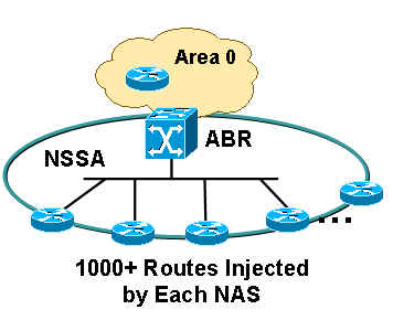
In order to resolve this design problem, Cisco recommends that the area to which NAS servers belong be configured in a Not so stubby area (NSSA) (see Figure 2):
Figure 2 – Configuration in a Not So Stubby Area 
Refer to OSPF Not-So-Stubby Area (NSSA) for more information on OSPF NSSAs.
Here are the benefits if you define an area as NSSA:
-
All NAS routes can be summarized at the ABR because ABR regenerates/translates LSA type 7 into LSA type 5.
-
Each POP will not carry routes that belong to another POP because NSSA does not allow external LSAs.
The configuration of redistributed, connected subnets is necessary in all NASs because the IP address pools across all NASs are not static—any NAS can carry any IP address within that central IP address range.
NAS1(config)# router ospf 1
NAS1(config-router)# redistribute connected subnets
NAS1(config-router)# end
If you perform this configuration on all NASs, a summarization configuration is performed on the ABR because all LSA type 7s are regenerated on the ABR and translated into LSA type 5s. Because the ABR generates a completely new LSA type 5 and the advertising router ID is the ABR router's ID, the ABR acts as the ASBR and allows the summarization of the routes that were previously LSA type 7s (originated by the NASs).
ABR(config)# router ospf 1
ABR(config-router)# summary-address 192.168.0.0 255.255.192.0
ABR(config-router)# end
Notice that the area between the ABR and the NAS is NSSA, which can be configured as follows:
ABR(config)# router ospf 1
ABR(config-router)# network 10.10.10.0 0.0.0.255 area 1 nssa
ABR(config-router)# end
Area Scalability Issue
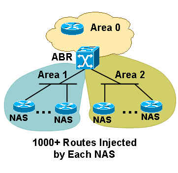
If you have many NAS servers in one area, and each NAS redistributes 1000 or more routes into the area, the question arises—how many NAS servers must each area comprise? If all NAS servers are in the same area, the area can become unstable because the area needs to carry 1000 or more routes from all NAS servers. In this example of 14 NAS servers, it can potentially redistribute 14000 routes, which is a huge number. In order to bring more scalability to the area, Cisco recommends that you divide the area into several sub-areas, to ensure that each area does not affect other areas if some instability occurs in one area (see Figure 3):
Figure 3 – Divide the Area 
In order to determine the number of NAS servers to keep in one area, you must ascertain the number of routes each NAS injects. Three NAS servers in one area can be enough if each NAS injects 3000 or more routes. Do not put too few NAS servers in each area because, if you have too many areas, the ABR can become overloaded due to the creation of summarizations into each area. However, you can resolve this problem if you make all areas totally stubby NSSA, which does not allow redistribution of any summary routes into the area. This action reduces the amount of information each NAS carries in addition to its own 1000 or more routes, and reduces the amount of load the ABR carries through the redistribution of summary LSAs into each area. Add the no-summary keyword on the ABR to perform the configuration, as shown here:
ABR#(config)# router ospf 1
ABR#(config-router)# network 10.10.10.0 0.0.0.255 area 1 nssa no-summary
ABR#(config-router)# end
The link between the ABR and the NAS servers does not need to go out in each area so the ABR does not need to create summaries into each area for these connected routes. The major advantage of NSSA is that all 3000 or more routes in one area do not leak into other areas since NSSA does not carry external LSAs. When the ABR translates all the NSSA LSA type 7s into area 0, it does not send any LSA type 5s into other areas because of the NSSA characteristics.
Conclusion
Designing the ISP dial network can be a challenging task, but with a few considerations it can be improved and provide a more scalable solution. The incorporation of NSSA can be effective in scalability management because it allows a significant reduction in the amount of routes that each NAS has to carry when compared to a situation where NSSA is not used. Summarization also helps reduce the size of the routing table, especially in the case of the central IP address pool, because the redistribute connected configuration command is required on the NAS servers. Contiguous IP address block assignment in each NAS also helps during the summarization because each POP can be summarized into one large block and the core does not have to carry an overabundance of routes.
 Feedback