Feedback
Contents
- Getting Started
- Configuring the Controller Using the Configuration Wizard
- Connecting the Console Port of the Controller
- Configuring the Controller (GUI)
- Configuring the Controller—Using the CLI Configuration Wizard
- Using the Controller Web GUI
- Guidelines and Limitations
- Logging On to the GUI
- Logging out of the GUI
- Enabling Web and Secure Web Modes
- Enabling Web and Secure Web Modes (GUI)
- Enabling Web and Secure Web Modes (CLI)
- Loading an Externally Generated SSL Certificate
- Information About Externally Generated SSL Certificates
- Loading an SSL Certificate (GUI)
- Loading an SSL Certificate (CLI)
- Using the Controller CLI
- Logging on to the Controller CLI
- Guidelines and Limitations
- Using a Local Serial Connection
- Using a Remote Ethernet Connection
- Logging Out of the CLI
- Navigating the CLI
- Using the AutoInstall Feature for Controllers Without a Configuration
- Information About the AutoInstall Feature
- Guidelines and Limitations
- Obtaining an IP Address Through DHCP and Downloading a Configuration File from a TFTP Server
- Selecting a Configuration File
- Example: AutoInstall Operation
- Managing the Controller System Date and Time
- Information About Controller System Date and Time
- Guidelines and Limitations
- Configuring an NTP Server to Obtain the Date and Time
- Configuring NTP Authentication (GUI)
- Configuring NTP Authentication (CLI)
- Configuring the Date and Time (GUI)
- Configuring the Date and Time (CLI)
- Configuring Telnet and Secure Shell Sessions
- Information About Telnet and SSH
- Guidelines and Limitations
- Configuring Telnet and SSH Sessions (GUI)
- Configuring Telnet and SSH Sessions (CLI)
- Troubleshooting Access Points Using Telnet or SSH
- Guidelines and Limitations
- Troubleshooting Access Points Using Telnet or SSH (GUI)
- Troubleshooting Access Points Using Telnet or SSH (CLI)
- Managing the Controller Wirelessly
- Enabling Wireless Connections (GUI)
- Enabling Wireless Connections (CLI)
Getting Started
Connecting the Console Port of the Controller
Before you can configure the controller for basic operations, you need to connect it to a PC that uses a VT-100 terminal emulation program (such as HyperTerminal, ProComm, Minicom, or Tip).
NoteOn Cisco 5500 Series Controllers, you can use either the RJ-45 console port or the USB console port. If you use the USB console port, plug the 5-pin mini Type B connector into the controller’s USB console port and the other end of the cable into the PC’s USB Type A port. The first time that you connect a Windows PC to the USB console port, you are prompted to install the USB console driver. Follow the installation prompts to install the driver. The USB console driver maps to a COM port on your PC; you then need to map the terminal emulator application to the COM port.
Configuring the Controller (GUI)
Configuring the Controller—Using the CLI Configuration Wizard
Before You Begin
- The available options appear in brackets after each configuration parameter. The default value appears in all uppercase letters.
- If you enter an incorrect response, the controller provides you with an appropriate error message, such as “Invalid Response,” and returns you to the wizard prompt.
- Press the hyphen key if you ever need to return to the previous command line.
Step 1 When prompted to terminate the AutoInstall process, enter yes. If you do not enter yes, the AutoInstall process begins after 30 seconds.
Note The AutoInstall feature downloads a configuration file from a TFTP server and then loads the configuration onto the controller automatically.
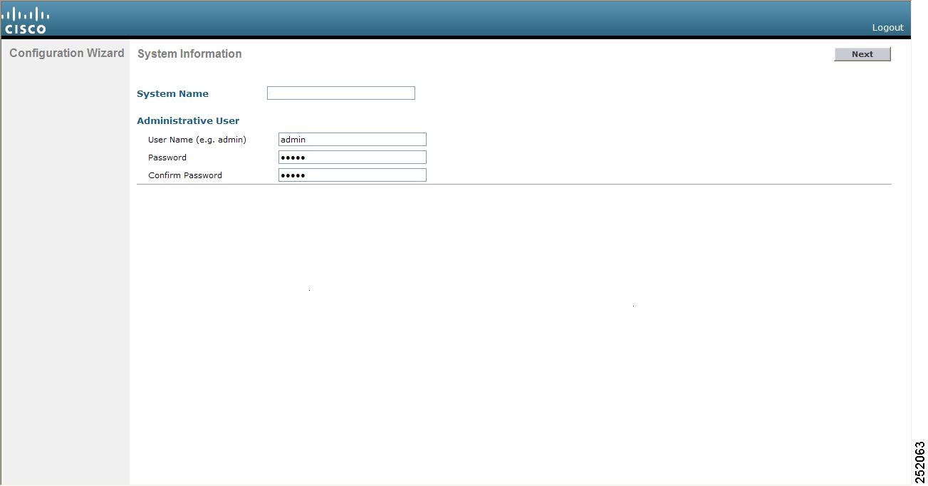
Step 2 Enter the system name, which is the name that you want to assign to the controller. You can enter up to 31 ASCII characters. Step 3 Enter the administrative username and password to be assigned to this controller. You can enter up to 24 ASCII characters for each. Starting in release 7.0.116.0, the following password policy has been implemented:
- No character in the password must be repeated more than three times consecutively.
- The new password must not be the same as the associated username and not be the username reversed.
- The password must not be cisco, ocsic, or any variant obtained by changing the capitalization of letters of the word Cisco. In addition, you cannot substitute 1, I, or ! for i, 0 for o, or $ for s.
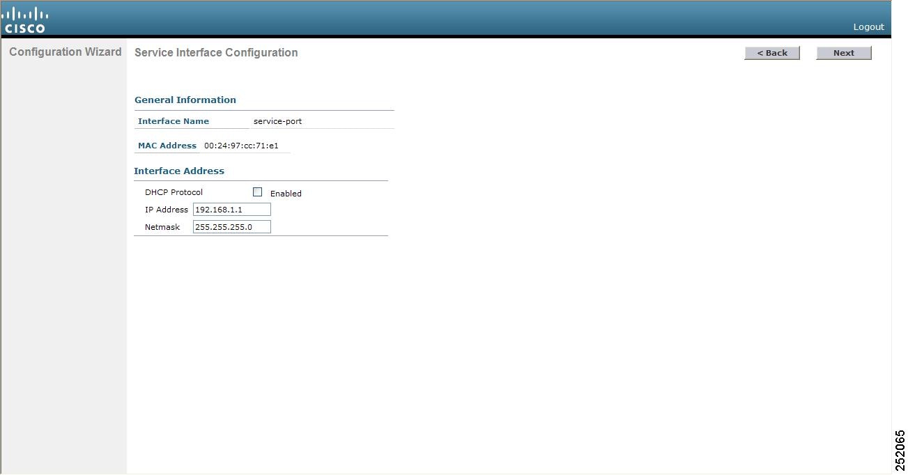
Step 4 If you want the controller’s service-port interface to obtain an IP address from a DHCP server, enter DHCP. If you do not want to use the service port or if you want to assign a static IP address to the service port, enter none.
Note The service-port interface controls communications through the service port. Its IP address must be on a different subnet from the management interface. This configuration enables you to manage the controller directly or through a dedicated management network to ensure service access during network downtime.
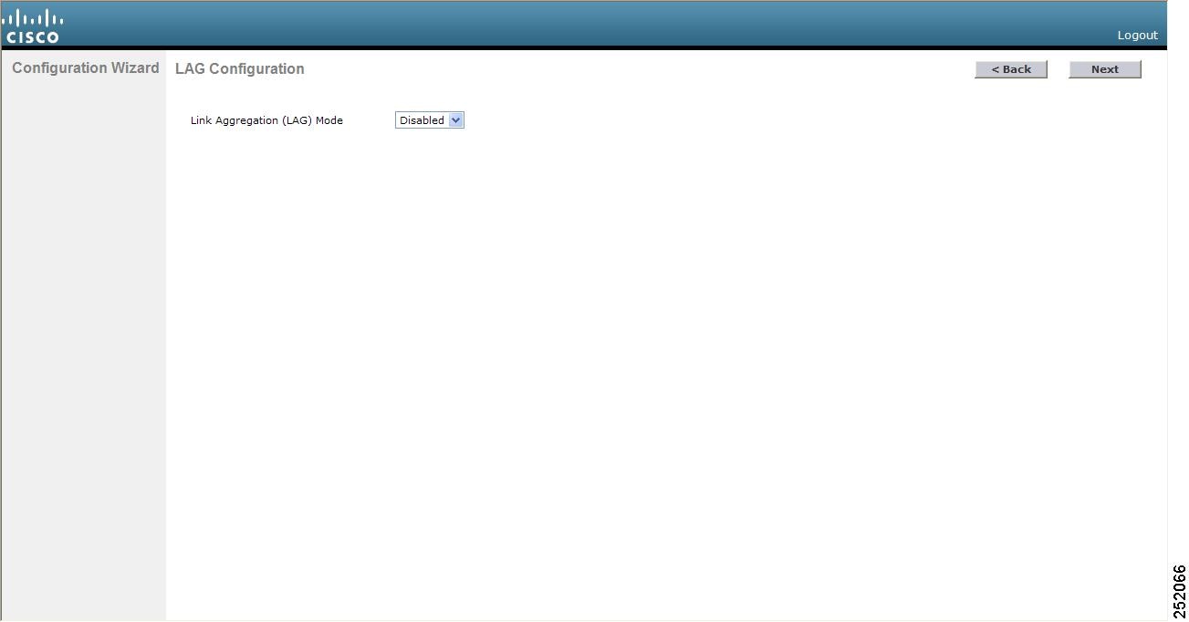
Step 5 If you entered none in Step 4, enter the IP address and netmask for the service-port interface on the next two lines. Step 6 Enable or disable link aggregation (LAG) by choosing yes or NO. Step 7 Enter the IP address of the management interface.
Note The management interface is the default interface for in-band management of the controller and connectivity to enterprise services such as AAA servers.
Step 8 Enter the IP address of the management interface netmask. Step 9 Enter the IP address of the default router. Step 10 Enter the VLAN identifier of the management interface (either a valid VLAN identifier or 0 for an untagged VLAN). The VLAN identifier should be set to match the switch interface configuration. Step 11 Enter the IP address of the default DHCP server that will supply IP addresses to clients, the management interface of the controller, and optionally, the service port interface. Enter the IP address of the AP-manager interface.
Note This prompt does not appear for Cisco 5500 Series Controllers because you are not required to configure an AP-manager interface. The management interface acts like an AP-manager interface by default.
Step 12 Enter the IP address of the controller’s virtual interface. You should enter a fictitious unassigned IP address.
Note The virtual interface is used to support mobility management, DHCP relay, and embedded Layer 3 security such as guest web authentication and VPN termination. All controllers within a mobility group must be configured with the same virtual interface IP address.
Step 13 If desired, enter the name of the mobility group/RF group to which you want the controller to belong.
Note Although the name that you enter here is assigned to both the mobility group and the RF group, these groups are not identical. Both groups define clusters of controllers, but they have different purposes. All of the controllers in an RF group are usually also in the same mobility group and vice versa. However, a mobility group facilitates scalable, system-wide mobility and controller redundancy while an RF group facilitates scalable, system-wide dynamic RF management.
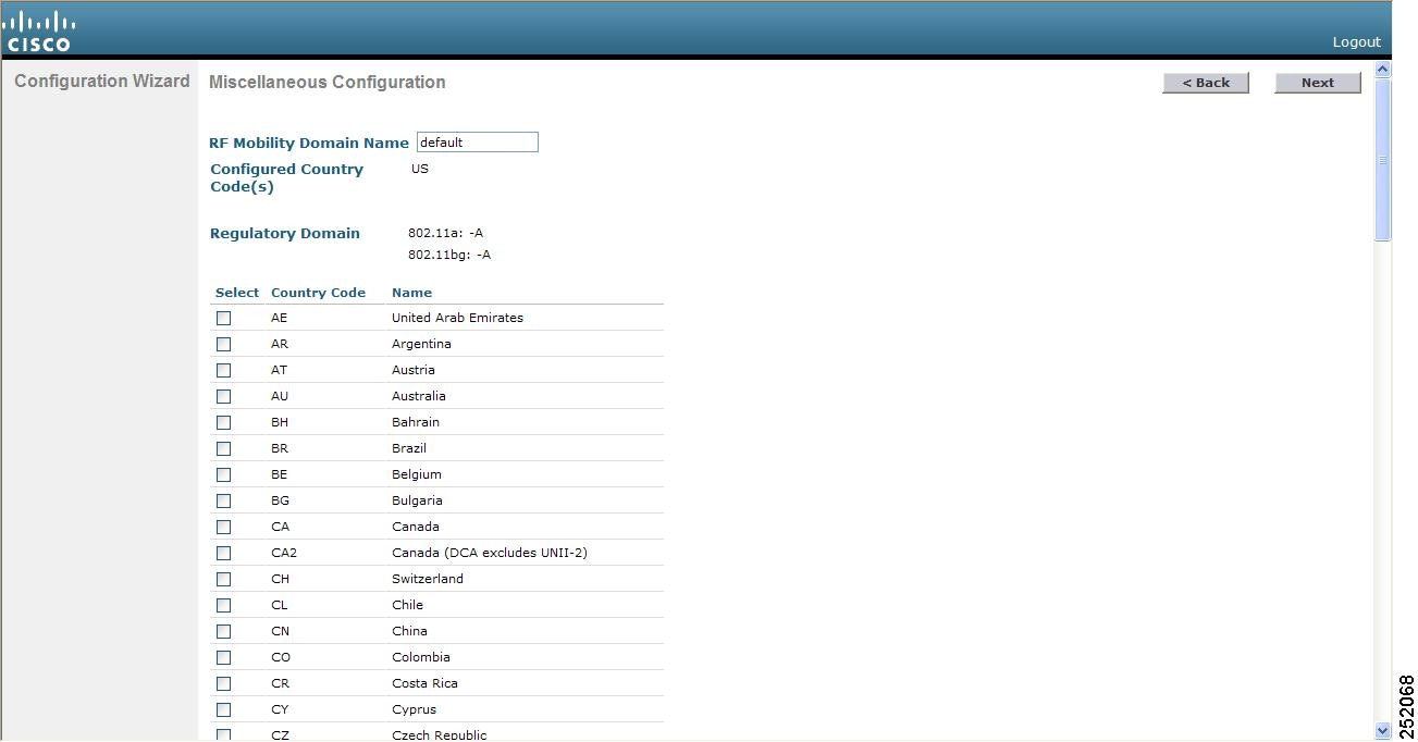
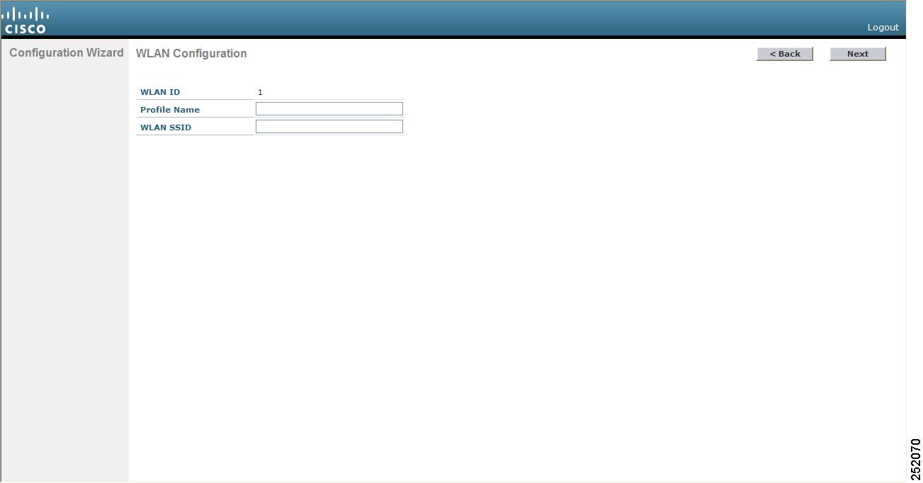
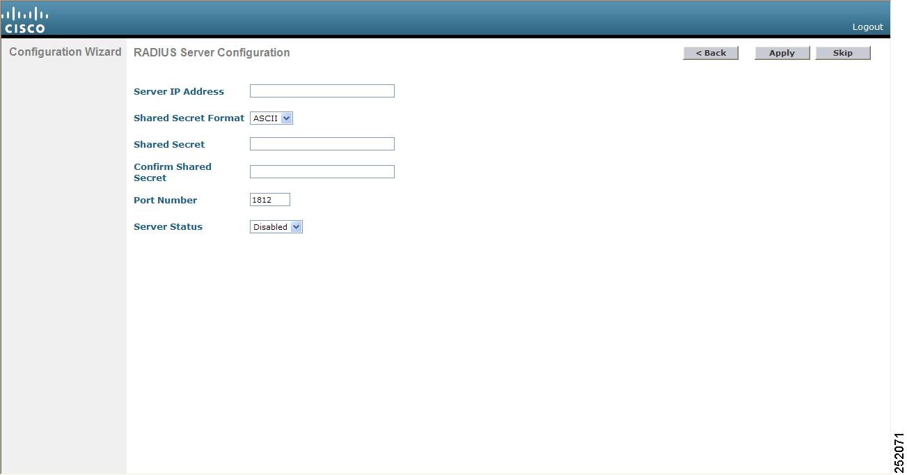
Step 14 Enter the network name or service set identifier (SSID). The SSID enables basic functionality of the controller and allows access points that have joined the controller to enable their radios. Step 15 Enter YES to allow clients to assign their own IP address or no to require clients to request an IP address from a DHCP server. Step 16 To configure a RADIUS server now, enter YES and then enter the IP address, communication port, and secret key of the RADIUS server. Otherwise, enter no. If you enter no, the following message appears: “Warning! The default WLAN security policy requires a RADIUS server. Please see the documentation for more details.” Step 17 Enter the code for the country in which the controller will be used.
Note
Note You can enter more than one country code if you want to manage access points in multiple countries from a single controller. To do so, separate the country codes with a comma (for example, US,CA,MX). After the configuration wizard runs, you need to assign each access point joined to the controller to a specific country.
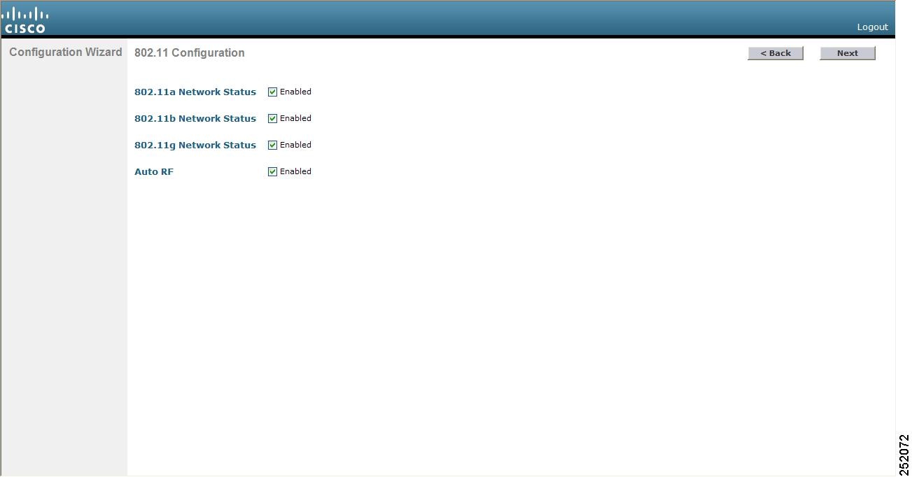
Step 18 Enable or disable the 802.11b, 802.11a, and 802.11g lightweight access point networks by entering YES or no. Step 19 Enable or disable the controller’s radio resource management (RRM) auto-RF feature by entering YES or no.
Note The auto-RF feature enables the controller to automatically form an RF group with other controllers. The group dynamically elects a leader to optimize RRM parameter settings, such as channel and transmit power assignment, for the group.
Step 20 If you want the controller to receive its time setting from an external Network Time Protocol (NTP) server when it powers up, enter YES to configure an NTP server. Otherwise, enter no.
Note The controller network module installed in a Cisco Integrated Services Router does not have a battery and cannot save a time setting. Therefore, it must receive a time setting from an external NTP server when it powers up.
Step 21 If you entered no in Step 20 and want to manually configure the system time on your controller now, enter YES. If you do not want to configure the system time now, enter no. Step 22 If you entered YES in Step 21, enter the current date in the MM/DD/YY format and the current time in the HH:MM:SS format. Step 23 When prompted to verify that the configuration is correct, enter yes or NO. The controller saves your configuration, reboots, and prompts you to log on.
Using the Controller Web GUI
A web browser, or graphical user interface (GUI), is built into each controller. It allows up to five users to simultaneously browse into the controller HTTP or HTTPS (HTTP + SSL) management pages to configure parameters and monitor the operational status for the controller and its associated access points.
NoteWe recommend that you enable the HTTPS interface and disable the HTTP interface to ensure more robust security for your Cisco UWN solution.
Guidelines and Limitations
Follow these guidelines when using the controller GUI:
- The GUI must be used on a PC running Windows 7, Windows XP SP1 (or later releases), or Windows 2000 SP4 (or later releases).
- The controller GUI is compatible with Microsoft Internet Explorer version 6.0 SP1 (or later versions) or Mozilla Firefox 2.0.0.11 (or later versions).
NoteOpera and Netscape are not supported.
- You can use either the service port interface or the management interface to access the GUI. We recommend that you use the service-port interface.
- You can use both HTTP and HTTPS when using the service port interface. HTTPS is enabled by default and HTTP can also be enabled. The default IP address to connect to the service port interface is 192.168.1.1.
- Click Help at the top of any page in the GUI to display online help. You might need to disable your browser’s pop-up blocker to view the online help.
Logging On to the GUI
Step 1 Enter the controller IP address in your browser’s address line. For a secure connection, enter https://ip-address. For a less secure connection, enter http://ip-address. Step 2 When prompted, enter a valid username and password and click OK. The controller Summary page appears.
Note The administrative username and password that you created in the configuration wizard are case sensitive. The default username is admin, and the default password is admin.
Enabling Web and Secure Web Modes
This section provides instructions to enable the distribution system port as a web port (using HTTP) or as a secure web port (using HTTPS). You can protect communication with the GUI by enabling HTTPS. HTTPS protects HTTP browser sessions by using the Secure Sockets Layer (SSL) protocol. When you enable HTTPS, the controller generates its own local web administration SSL certificate and automatically applies it to the GUI. You also have the option of downloading an externally generated certificate.
You can configure web and secure web mode using the controller GUI or CLI.
Enabling Web and Secure Web Modes (GUI)
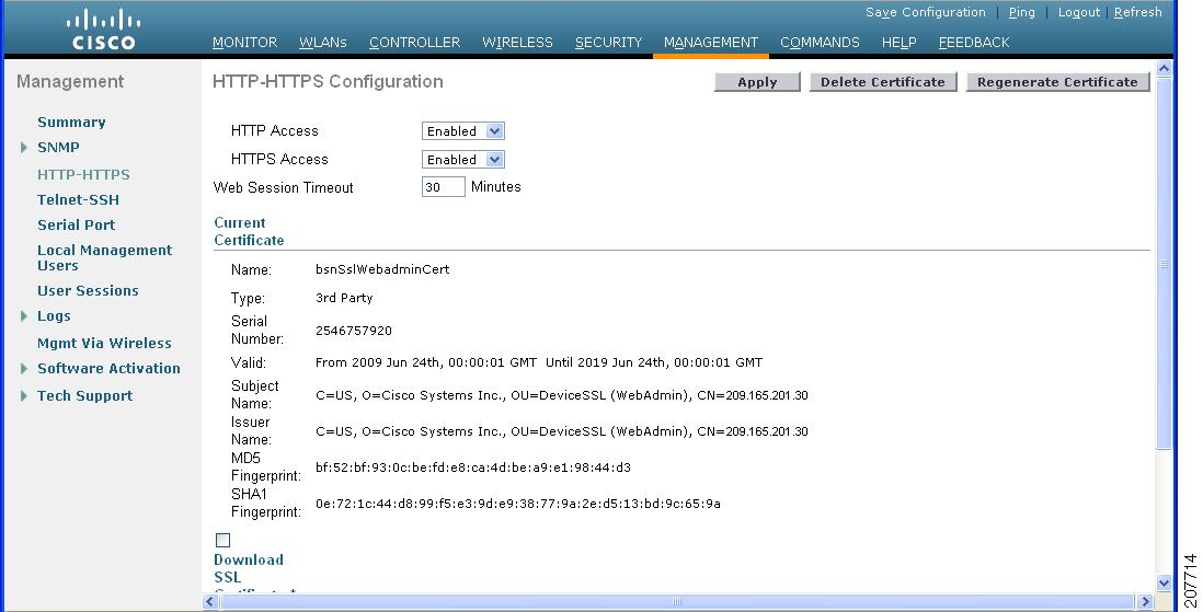
Step 1 Choose Management > HTTP to open the HTTP Configuration page. Step 2 To enable web mode, which allows users to access the controller GUI using “http://ip-address,” choose Enabled from the HTTP Access drop-down list. Otherwise, choose Disabled. The default value is Disabled. Web mode is not a secure connection. Step 3 To enable secure web mode, which allows users to access the controller GUI using “https://ip-address,” choose Enabled from the HTTPS Access drop-down list. Otherwise, choose Disabled. The default value is Enabled. Secure web mode is a secure connection. Step 4 In the Web Session Timeout text box, enter the amount of time (in minutes) before the web session times out due to inactivity. You can enter a value between 30 and 160 minutes (inclusive), and the default value is 30 minutes. Step 5 Click Apply to commit your changes. Step 6 If you enabled secure web mode in Step 3, the controller generates a local web administration SSL certificate and automatically applies it to the GUI. The details of the current certificate appear in the middle of the HTTP Configuration page.
Note If desired, you can delete the current certificate by clicking Delete Certificate and have the controller generate a new certificate by clicking Regenerate Certificate.
Step 7 Click Save Configuration to save your changes.
Enabling Web and Secure Web Modes (CLI)
Step 1 To enable or disable web mode, enter this command: config network webmode {enable | disable}
This command allows users to access the controller GUI using "http://ip-address"." The default value is disabled. Web mode is not a secure connection.
Step 2 To enable or disable secure web mode, enter this command: config network secureweb {enable | disable}
This command allows users to access the controller GUI using “https://ip-address.” The default value is enabled. Secure web mode is a secure connection.
Step 3 To enable or disable secure web mode with increased security, enter this command: config network secureweb cipher-option high {enable | disable}
This command allows users to access the controller GUI using “https://ip-address” but only from browsers that support 128-bit (or larger) ciphers. The default value is disabled.
Step 4 To enable or disable SSLv2 for web administration, enter this command: config network secureweb cipher-option sslv2 {enable | disable}
If you disable SSLv2, users cannot connect using a browser configured with SSLv2 only. They must use a browser that is configured to use a more secure protocol such as SSLv3 or later. The default value is disabled.
Step 5 To verify that the controller has generated a certificate, enter this command: Information similar to the following appears:
Web Administration Certificate................. Locally Generated
Web Authentication Certificate................. Locally Generated
Certificate compatibility mode:................ off
Step 6 (Optional) If you need to generate a new certificate, enter this command: config certificate generate webadmin
After a few seconds, the controller verifies that the certificate has been generated.
Step 7 To save the SSL certificate, key, and secure web password to nonvolatile RAM (NVRAM) so that your changes are retained across reboots, enter this command: Step 8 To reboot the controller, enter this command:
Loading an Externally Generated SSL Certificate
This section describes how to load an externally generated SSL certificate.
Information About Externally Generated SSL Certificates
You can use a TFTP server to download an externally generated SSL certificate to the controller. Follow these guidelines for using TFTP:
- If you load the certificate through the service port, the TFTP server must be on the same subnet as the controller because the service port is not routable, or you must create static routes on the controller. Also, if you load the certificate through the distribution system network port, the TFTP server can be on any subnet.
- A third-party TFTP server cannot run on the same PC as the Cisco WCS because the WCS built-in TFTP server and the third-party TFTP server require the same communication port.
NoteChained certificates are supported for web authentication only and not for the management certificate.
NoteEvery HTTPS certificate contains an embedded RSA key. The length of the key can vary from 512 bits, which is relatively insecure, to thousands of bits, which is very secure. When you obtain a new certificate from a Certificate Authority, make sure that the RSA key embedded in the certificate is at least 768 bits long.
Loading an SSL Certificate (GUI)
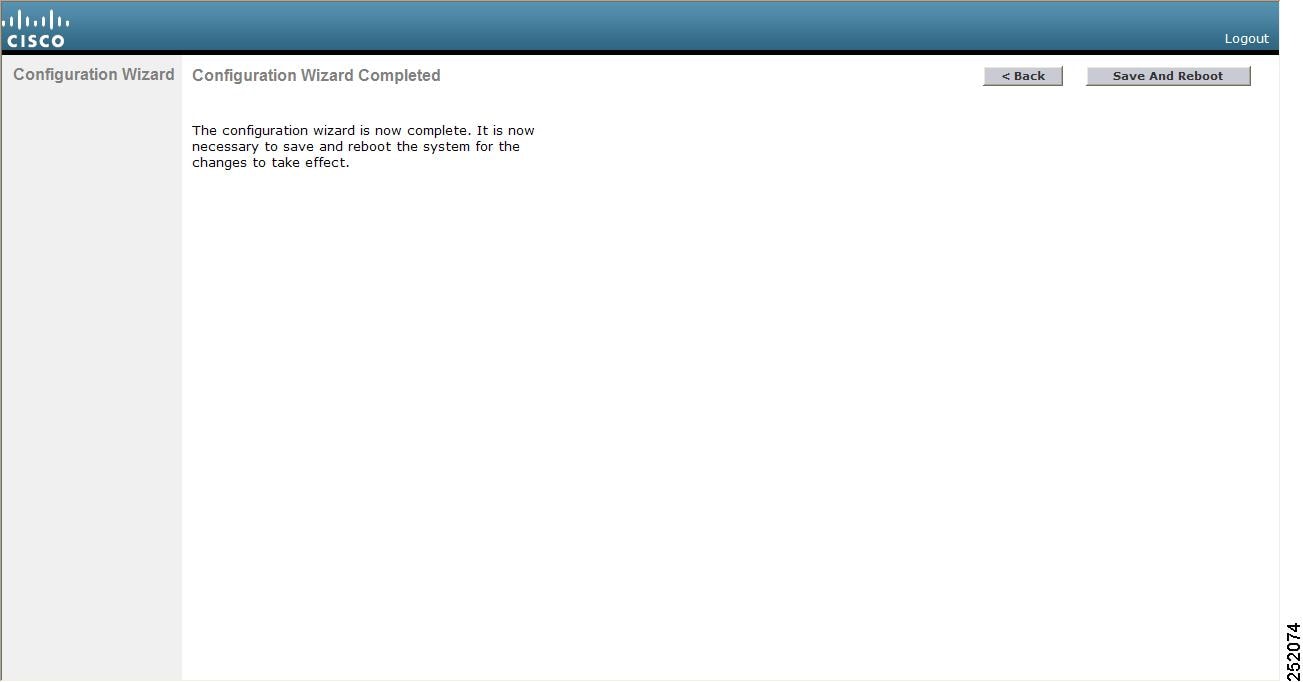
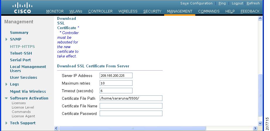
Step 1 On the HTTP Configuration page, select the Download SSL Certificate check box. Step 2 In the Server IP Address text box, enter the IP address of the TFTP server. Step 3 In the Maximum Retries text box, enter the maximum number of times that the TFTP server attempts to download the certificate. Step 4 In the Timeout text box, enter the amount of time (in seconds) that the TFTP server attempts to download the certificate. Step 5 In the Certificate File Path text box, enter the directory path of the certificate. Step 6 In the Certificate File Name text box, enter the name of the certificate (webadmincert_name.pem). Step 7 (Optional) In the Certificate Password text box, enter a password to encrypt the certificate. Step 8 Click Apply to commit your changes. Step 9 Click Save Configuration to save your changes. Step 10 To reboot the controller for your changes to take effect, choose Commands > Reboot > Reboot > Save and Reboot.
Loading an SSL Certificate (CLI)
Step 1 Use a password to encrypt the HTTPS certificate in a .PEM-encoded file. The PEM-encoded file is called a web administration certificate file (webadmincert_name.pem). Step 2 Move the webadmincert_name.pem file to the default directory on your TFTP server. Step 3 To view the current download settings, enter this command and answer n to the prompt: Information similar to the following appears:
Mode........................................... TFTP
Data Type...................................... Admin Cert
TFTP Server IP................................. xxx.xxx.xxx.xxx
TFTP Path...................................... <directory path>
TFTP Filename..................................
Are you sure you want to start? (y/n) n
Transfer Canceled
Step 4 Use these commands to change the download settings: transfer download datatype webauthcert
transfer download serverip TFTP_server IP_address
transfer download path absolute_TFTP_server_path_to_the_update_file
transfer download filename webadmincert_name.pem
Step 5 To set the password for the .PEM file so that the operating system can decrypt the web administration SSL key and certificate, enter this command: Step 6 To confirm the current download settings and start the certificate and key download, enter this command and answer y to the prompt: transfer download start
Information similar to the following appears:
Mode........................................... TFTP
Data Type...................................... Site Cert
TFTP Server IP................................. xxx.xxx.xxx.xxx
TFTP Path...................................... directory path
TFTP Filename.................................. webadmincert_name
Are you sure you want to start? (y/n) y
TFTP Webadmin cert transfer starting.
Certificate installed.
Please restart the switch (reset system) to use the new certificate.
Step 7 To save the SSL certificate, key, and secure web password to NVRAM so that your changes are retained across reboots, enter this command: save config Step 8 To reboot the controller, enter this command: reset system
Using the Controller CLI
A Cisco UWN solution command-line interface (CLI) is built into each controller. The CLI enables you to use a VT-100 terminal emulation program to locally or remotely configure, monitor, and control individual controllers and its associated lightweight access points. The CLI is a simple text-based, tree-structured interface that allows up to five users with Telnet-capable terminal emulation programs to access the controller.
NoteSee the Cisco Wireless LAN Controller Command Reference for information on specific commands.
NoteIf you want to input any strings from the XML configuration into CLI commands, you must enclose the strings in quotation marks.
Logging on to the Controller CLI
You can access the controller CLI using one of the following two methods:
- A direct serial connection to the controller console port
- A remote console session over Ethernet through the preconfigured service port or the distribution system ports
Before you log on to the CLI, configure your connectivity and environment variables based on the type of connection you use.
- Guidelines and Limitations
- Using a Local Serial Connection
- Using a Remote Ethernet Connection
- Logging Out of the CLI
- Navigating the CLI
Guidelines and Limitations
On Cisco 5500 Series Controllers, you can use either the RJ-45 console port or the USB console port. If you use the USB console port, plug the 5-pin mini Type B connector into the controller’s USB console port and the other end of the cable into the PC’s USB Type A port. The first time that you connect a Windows PC to the USB console port, you are prompted to install the USB console driver. Follow the installation prompts to install the driver. The USB console driver maps to a COM port on your PC; you then need to map the terminal emulator application to the COM port.
See the Configuring Telnet and SSH Sessions section for information on enabling Telnet sessions.
Using a Local Serial Connection
Before You BeginYou need these items to connect to the serial port:
- A PC that is running a VT-100 terminal emulation program (such as HyperTerminal, ProComm, Minicom, or Tip)
- A null-modem serial cable
To log on to the controller CLI through the serial port, follow these steps:
Step 1 Connect one end of a null-modem serial cable to the controller’s console port and the other end to your PC’s serial port. Step 2 Start the PC’s VT-100 terminal emulation program. Configure the terminal emulation program for these parameters:
- 9600 baud
- 8 data bits
- 1 stop bit
- No parity
- No hardware flow control
Note Minimum serial timeout on Controller is 15 seconds instead of 1 minute.
Note The controller serial port is set for a 9600 baud rate and a short timeout. If you would like to change either of these values, enter config serial baudrate baudrate and config serial timeout timeout to make your changes. If you enter config serial timeout 0, serial sessions never time out.
Step 3 When prompted, enter a valid username and password to log into the controller. The administrative username and password that you created in the configuration wizard are case sensitive.
Note The default username is admin, and the default password is admin.
The CLI displays the root level system prompt:
Note The system prompt can be any alphanumeric string up to 31 characters. You can change it by entering the config prompt command.
Using a Remote Ethernet Connection
Before You BeginYou need these items to connect to a controller remotely:
- A PC with access to the controller over the Ethernet network
- The IP address of the controller
- A VT-100 terminal emulation program or a DOS shell for the Telnet session
NoteBy default, controllers block Telnet sessions. You must use a local connection to the serial port to enable Telnet sessions.
Step 1 Verify that your VT-100 terminal emulation program or DOS shell interface is configured with these parameters: Step 2 Use the controller IP address to Telnet to the CLI. Step 3 When prompted, enter a valid username and password to log into the controller. The administrative username and password that you created in the configuration wizard are case sensitive.
Note The default username is admin, and the default password is admin.
The CLI displays the root level system prompt.
Note The system prompt can be any alphanumeric string up to 31 characters. You can change it by entering the config prompt command.
Logging Out of the CLI
When you finish using the CLI, navigate to the root level and enter logout. The system prompts you to save any changes you made to the volatile RAM.
NoteThe CLI automatically logs you out without saving any changes after 5 minutes of inactivity. You can set the automatic logout from 0 (never log out) to 160 minutes using the config serial timeout command.
Navigating the CLI
The CLI is organized into five levels:
When you log into the CLI, you are at the root level. From the root level, you can enter any full command without first navigating to the correct command level.
Using the AutoInstall Feature for Controllers Without a Configuration
This section describes how to use the AutoInstall feature for controllers without a configuration.
Information About the AutoInstall Feature
When you boot up a controller that does not have a configuration, the AutoInstall feature can download a configuration file from a TFTP server and then load the configuration onto the controller automatically.
If you create a configuration file on a controller that is already on the network (or through a WCS filter), place that configuration file on a TFTP server, and configure a DHCP server so that a new controller can get an IP address and TFTP server information, the AutoInstall feature can obtain the configuration file for the new controller automatically.
When the controller boots, the AutoInstall process starts. The controller does not take any action until AutoInstall is notified that the configuration wizard has started. If the wizard has not started, the controller has a valid configuration.
If AutoInstall is notified that the configuration wizard has started (which means that the controller does not have a configuration), AutoInstall waits for an additional 30 seconds. This time period gives you an opportunity to respond to the first prompt from the configuration wizard:
Would you like to terminate autoinstall? [yes]:When the 30-second abort timeout expires, AutoInstall starts the DHCP client. You can abort the AutoInstall task even after this 30-second timeout if you enter Yes at the prompt. However, AutoInstall cannot be aborted if the TFTP task has locked the flash and is in the process of downloading and installing a valid configuration file.
Guidelines and Limitations
- Obtaining an IP Address Through DHCP and Downloading a Configuration File from a TFTP Server
- Selecting a Configuration File
- Example: AutoInstall Operation
Obtaining an IP Address Through DHCP and Downloading a Configuration File from a TFTP Server
AutoInstall attempts to obtain an IP address from the DHCP server until the DHCP process is successful or until you abort the AutoInstall process. The first interface to successfully obtain an IP address from the DHCP server registers with the AutoInstall task. The registration of this interface causes AutoInstall to begin the process of obtaining TFTP server information and downloading the configuration file.
Following the acquisition of the DHCP IP address for an interface, AutoInstall begins a short sequence of events to determine the host name of the controller and the IP address of the TFTP server. Each phase of this sequence gives preference to explicitly configured information over default or implied information and to explicit host names over explicit IP addresses.
- If at least one Domain Name System (DNS) server IP address is learned through DHCP, AutoInstall creates a /etc/resolv.conf file. This file includes the domain name and the list of DNS servers that have been received. The Domain Name Server option provides the list of DNS servers, and the Domain Name option provides the domain name.
- If the domain servers are not on the same subnet as the controller, static route entries are installed for each domain server. These static routes point to the gateway that is learned through the DHCP Router option.
- The host name of the controller is determined in this order by one of the following:
- If the DHCP Host Name option was received, this information (truncated at the first period [.]) is used as the host name for the controller.
- A reverse DNS lookup is performed on the controller IP address. If DNS returns a hostname, this name (truncated at the first period [.]) is used as the hostname for the controller.
- The IP address of the TFTP server is determined in this order by one of the following:
- If AutoInstall received the DHCP TFTP Server Name option, AutoInstall performs a DNS lookup on this server name. If the DNS lookup is successful, the returned IP address is used as the IP address of the TFTP server.
- If the DHCP Server Host Name (sname) text box is valid, AutoInstall performs a DNS lookup on this name. If the DNS lookup is successful, the IP address that is returned is used as the IP address of the TFTP server.
- If AutoInstall received the DHCP TFTP Server Address option, this address is used as the IP address of the TFTP server.
- AutoInstall performs a DNS lookup on the default TFTP server name (cisco-wlc-tftp). If the DNS lookup is successful, the IP address that is received is used as the IP address of the TFTP server.
- If the DHCP server IP address (siaddr) text box is nonzero, this address is used as the IP address of the TFTP server.
- The limited broadcast address (255.255.255.255) is used as the IP address of the TFTP server.
- If the TFTP server is not on the same subnet as the controller, a static route (/32) is installed for the IP address of the TFTP server. This static route points to the gateway that is learned through the DHCP Router option.
Selecting a Configuration File
After the hostname and TFTP server have been determined, AutoInstall attempts to download a configuration file. AutoInstall performs three full download iterations on each interface that obtains a DHCP IP address. If the interface cannot download a configuration file successfully after three attempts, the interface does not attempt further.
The first configuration file that is downloaded and installed successfully triggers a reboot of the controller. After the reboot, the controller runs the newly downloaded configuration.
AutoInstall searches for configuration files in the order in which the names are listed:
- The filename that is provided by the DHCP Boot File Name option
- The filename that is provided by the DHCP File text box
- host name-confg
- host name.cfg
- base MAC address-confg (for example, 0011.2233.4455-confg)
- serial number-confg
- ciscowlc-confg
- ciscowlc.cfg
AutoInstall runs through this list until it finds a configuration file. It stops running if it does not find a configuration file after it cycles through this list three times on each registered interface.
NoteThe downloaded configuration file can be a complete configuration, or it can be a minimal configuration that provides enough information for the controller to be managed by the Cisco Prime Infrastructure. Full configuration can then be deployed directly from the Prime Infrastructure.
NoteAutoInstall does not expect the switch connected to the controller to be configured for either channels. AutoInstall works with a service port in LAG configuration.
NoteCisco Prime Infrastructure provides AutoInstall capabilities for controllers. A Cisco Prime Infrastructure administrator can create a filter that includes the host name, the MAC address, or the serial number of the controller and associate a group of templates (a configuration group) to this filter rule. The Prime Infrastructure pushes the initial configuration to the controller when the controller boots up initially. After the controller is discovered, the Prime Infrastructure pushes the templates that are defined in the configuration group. For more information about the AutoInstall feature and Cisco Prime Infrastructure, see the Cisco Prime Infrastructure documentation.
Example: AutoInstall Operation
The following is an example of an AutoInstall process from start to finish:
Welcome to the Cisco Wizard Configuration Tool
Use the '-' character to backup
Would you like to terminate autoinstall? [yes]:
AUTO-INSTALL: starting now...
AUTO-INSTALL: interface 'service-port' - setting DHCP TFTP Filename ==> 'abcd-confg'
AUTO-INSTALL: interface 'service-port' - setting DHCP TFTP Server IP ==> 1.100.108.2
AUTO-INSTALL: interface 'service-port' - setting DHCP siaddr ==> 1.100.108.2
AUTO-INSTALL: interface 'service-port' - setting DHCP Domain Server[0] ==> 1.100.108.2
AUTO-INSTALL: interface 'service-port' - setting DHCP Domain Name ==> 'engtest.com'
AUTO-INSTALL: interface 'service-port' - setting DHCP yiaddr ==> 172.19.29.253
AUTO-INSTALL: interface 'service-port' - setting DHCP Netmask ==> 255.255.255.0
AUTO-INSTALL: interface 'service-port' - setting DHCP Gateway ==> 172.19.29.1
AUTO-INSTALL: interface 'service-port' registered
AUTO-INSTALL: interation 1 -- interface 'service-port'
AUTO-INSTALL: DNS reverse lookup 172.19.29.253 ===> 'wlc-1'
AUTO-INSTALL: hostname 'wlc-1'
AUTO-INSTALL: TFTP server 1.100.108.2 (from DHCP Option 150)
AUTO-INSTALL: attempting download of 'abcd-confg'
AUTO-INSTALL: TFTP status - 'TFTP Config transfer starting.' (2)
AUTO-INSTALL: interface 'management' - setting DHCP file ==> 'bootfile1'
AUTO-INSTALL: interface 'management' - setting DHCP TFTP Filename ==> 'bootfile2-confg'
AUTO-INSTALL: interface 'management' - setting DHCP siaddr ==> 1.100.108.2
AUTO-INSTALL: interface 'management' - setting DHCP Domain Server[0] ==> 1.100.108.2
AUTO-INSTALL: interface 'management' - setting DHCP Domain Server[1] ==> 1.100.108.3
AUTO-INSTALL: interface 'management' - setting DHCP Domain Server[2] ==> 1.100.108.4
AUTO-INSTALL: interface 'management' - setting DHCP Domain Name ==> 'engtest.com'
AUTO-INSTALL: interface 'management' - setting DHCP yiaddr ==> 1.100.108.238
AUTO-INSTALL: interface 'management' - setting DHCP Netmask ==> 255.255.254.0
AUTO-INSTALL: interface 'management' - setting DHCP Gateway ==> 1.100.108.1
AUTO-INSTALL: interface 'management' registered
AUTO-INSTALL: TFTP status - 'Config file transfer failed - Error from server: File not found' (3)
AUTO-INSTALL: attempting download of 'wlc-1-confg'
AUTO-INSTALL: TFTP status - 'TFTP Config transfer starting.' (2)
AUTO-INSTALL: TFTP status - 'TFTP receive complete... updating configuration.' (2)
AUTO-INSTALL: TFTP status - 'TFTP receive complete... storing in flash.' (2)
AUTO-INSTALL: TFTP status - 'System being reset.' (2)
Resetting system
Managing the Controller System Date and Time
This section describes how to manage the date and time of a controller system.
- Information About Controller System Date and Time
- Guidelines and Limitations
- Configuring an NTP Server to Obtain the Date and Time
- Configuring NTP Authentication (GUI)
- Configuring NTP Authentication (CLI)
- Configuring the Date and Time (GUI)
- Configuring the Date and Time (CLI)
Information About Controller System Date and Time
You can configure the controller system date and time at the time of configuring the controller using the configuration wizard. If you did not configure the system date and time through the configuration wizard or if you want to change your configuration, you can follow the instructions in this section to configure the controller to obtain the date and time from a Network Time Protocol (NTP) server or to configure the date and time manually. Greenwich Mean Time (GMT) is used as the standard for setting the time zone on the controller.
You can also configure an authentication mechanism between various NTP servers.
Guidelines and Limitations
- If you are configuring wIPS, you must set the controller time zone to UTC.
- Cisco Aironet lightweight access points might not connect to the controller if the date and time are not set properly. Set the current date and time on the controller before allowing the access points to connect to it.
- You can configure an authentication channel between the controller and the NTP server.
Configuring an NTP Server to Obtain the Date and Time
Configuring NTP Authentication (GUI)
Step 1 Choose Controller > NTP > Servers to open the NTP Servers page. Step 2 Click New to add an NTP server. Step 3 Choose a server priority from the Server Index (Priority) drop-down list. Step 4 Enter the NTP server IP address in the Server IP Address text box. Step 5 Enable NTP server authentication by selecting the NTP Server Authentication check box. Step 6 Click Apply. Step 7 Choose Controller > NTP > Keys. Step 8 Click New to create a key. Step 9 Enter the key index in the Key Index text box. Step 10 Choose the key format from the Key Format drop-down list. Step 11 Enter the key in the Key text box. Step 12 Click Apply.
Configuring NTP Authentication (CLI)
Note
- config time ntp auth enable server-index key-index
- config time ntp auth disable server-index
- config time ntp key-auth add key-index md5 key-format key
- To delete an authentication key, enter this command: config time ntp key-auth delete key-index
- To view the list of NTP key Indices, enter this command: show ntp-keys
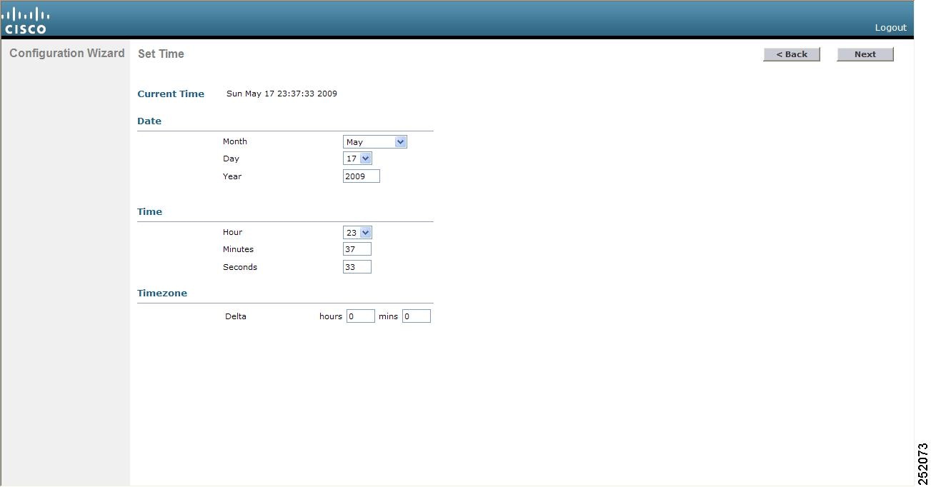
Configuring the Date and Time (GUI)
Step 1 Choose Commands > Set Time to open the Set Time page. Step 2 In the Timezone area, choose your local time zone from the Location drop-down list.
Note When you choose a time zone that uses Daylight Saving Time (DST), the controller automatically sets its system clock to reflect the time change when DST occurs. In the United States, DST starts on the second Sunday in March and ends on the first Sunday in November.
Note You cannot set the time zone delta on the controller GUI. However, if you do so on the controller CLI, the change is reflected in the Delta Hours and Mins text boxes on the controller GUI.
Step 3 Click Set Timezone to apply your changes. Step 4 In the Date area, choose the current local month and day from the Month and Day drop-down lists, and enter the year in the Year text box. Step 5 In the Time area, choose the current local hour from the Hour drop-down list, and enter the minutes and seconds in the Minutes and Seconds text boxes.
Note If you change the time zone location after setting the date and time, the values in the Time area are updated to reflect the time in the new time zone location. For example, if the controller is currently configured for noon Eastern time and you change the time zone to Pacific time, the time automatically changes to 9:00 a.m.
Step 6 Click Set Date and Time to apply your changes. Step 7 Click Save Configuration to save your changes.
Configuring the Date and Time (CLI)
Step 1 To configure the current local date and time in GMT on the controller, enter this command: config time manual mm/dd/yy hh:mm:ss
Note When setting the time, the current local time is entered in terms of GMT and as a value between 00:00 and 24:00. For example, if it is 8:00 a.m. Pacific time in the United States, you would enter 16:00 because the Pacific time zone is 8 hours behind GMT.
Step 2 Perform one of the following to set the time zone for the controller:
- To set the time zone location in order to have Daylight Saving Time (DST) set automatically when it occurs, enter this command: config time timezone location location_index where location_index is a number representing one of the following time zone locations:
- (GMT-12:00) International Date Line West
- (GMT-11:00) Samoa
- (GMT-10:00) Hawaii
- (GMT-9:00) Alaska
- (GMT-8:00) Pacific Time (US and Canada)
- (GMT-7:00) Mountain Time (US and Canada)
- (GMT-6:00) Central Time (US and Canada)
- (GMT-5:00) Eastern Time (US and Canada)
- (GMT-4:00) Atlantic Time (Canada)
- (GMT-3:00) Buenos Aires (Argentina)
- (GMT-2:00) Mid-Atlantic
- (GMT-1:00) Azores
- (GMT) London, Lisbon, Dublin, Edinburgh (default value)
- (GMT +1:00) Amsterdam, Berlin, Rome, Vienna
- (GMT +2:00) Jerusalem
- (GMT +3:00) Baghdad
- (GMT +4:00) Muscat, Abu Dhabi
- (GMT +4:30) Kabul
- (GMT +5:00) Karachi, Islamabad, Tashkent
- (GMT +5:30) Colombo, Kolkata, Mumbai, New Delhi
- (GMT +5:45) Katmandu
- (GMT +6:00) Almaty, Novosibirsk
- (GMT +6:30) Rangoon
- (GMT +7:00) Saigon, Hanoi, Bangkok, Jakarta
- (GMT +8:00) Hong Kong, Beijing, Chongqing
- (GMT +9:00) Tokyo, Osaka, Sapporo
- (GMT +9:30) Darwin
- (GMT+10:00) Sydney, Melbourne, Canberra
- (GMT+11:00) Magadan, Solomon Is., New Caledonia
- (GMT+12:00) Kamchatka, Marshall Is., Fiji
- (GMT+12:00) Auckland (New Zealand)
Note If you enter this command, the controller automatically sets its system clock to reflect DST when it occurs. In the United States, DST starts on the second Sunday in March and ends on the first Sunday in November.
- To manually set the time zone so that DST is not set automatically, enter this command: config time timezone delta_hours delta_mins where delta_hours is the local hour difference from GMT, and delta_mins is the local minute difference from GMT. When manually setting the time zone, enter the time difference of the local current time zone with respect to GMT (+/–). For example, Pacific time in the United States is 8 hours behind GMT. Therefore, it is entered as –8.
Note You can manually set the time zone and prevent DST from being set only on the controller CLI.
Step 3 To save your changes, enter this command: Step 4 To verify that the controller shows the current local time with respect to the local time zone, enter this command: Information similar to the following appears:
Time.................................... Thu Apr  7 13:56:37 2011
Timezone delta........................... 0:0
Timezone location....................... (GMT +5:30) Colombo, New Delhi, Chennai, Kolkata

NTP Servers
    NTP Polling Interval.........................     3600

     Index     NTP Key Index     NTP Server      	NTP Msg Auth Status
    -------  ---------------------------------------------------------------
       1              1           209.165.200.225 				 AUTH SUCCESS
Note If you configured the time zone location, the Timezone Delta value is set to “0:0.” If you manually configured the time zone using the time zone delta, the Timezone Location is blank.
Configuring Telnet and Secure Shell Sessions
This section describes how to configure Telnet and Secure Shell (SSH) sessions.
- Information About Telnet and SSH
- Guidelines and Limitations
- Configuring Telnet and SSH Sessions (GUI)
- Configuring Telnet and SSH Sessions (CLI)
- Troubleshooting Access Points Using Telnet or SSH
Configuring Telnet and SSH Sessions (GUI)
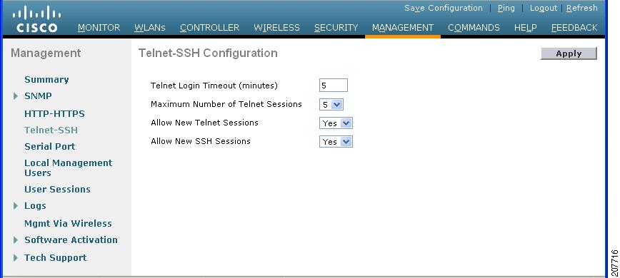
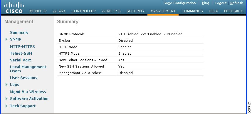
Step 1 Choose Management > Telnet-SSH to open the Telnet-SSH Configuration page. Step 2 In the Telnet Login Timeout text box, enter the number of minutes that a Telnet session is allowed to remain inactive before being terminated. The valid range is 0 to 160 minutes (inclusive), and the default value is 5 minutes. A value of 0 indicates no timeout. Step 3 From the Maximum Number of Sessions drop-down list, choose the number of simultaneous Telnet or SSH sessions allowed. The valid range is 0 to 5 sessions (inclusive), and the default value is 5 sessions. A value of zero indicates that Telnet/SSH sessions are disallowed. Step 4 From the Allow New Telnet Sessions drop-down list, choose Yes or No to allow or disallow new Telnet sessions on the controller. The default value is No. Step 5 From the Allow New SSH Sessions drop-down list, choose Yes or No to allow or disallow new SSH sessions on the controller. The default value is Yes. Step 6 Click Apply to commit your changes. Step 7 Click Save Configuration to save your changes. Step 8 To see a summary of the Telnet configuration settings, choose Management > Summary. The Summary page appears. This page shows whether additional Telnet and SSH sessions are permitted.
Configuring Telnet and SSH Sessions (CLI)
Step 1 To allow or disallow new Telnet sessions on the controller, enter this command: Step 2 To allow or disallow new SSH sessions on the controller, enter this command: Step 3 To specify the number of minutes that a Telnet session is allowed to remain inactive before being terminated, enter this command: config sessions timeout timeout
where timeout is a value between 0 and 160 minutes (inclusive). The default value is 5 minutes. A value of 0 indicates no timeout.
Step 4 To specify the number of simultaneous Telnet or SSH sessions allowed, enter this command: config sessions maxsessions session_num
where session_num is a value between 0 and 5 (inclusive). The default value is 5 sessions. A value of zero indicates that Telnet/SSH sessions are disallowed.
Step 5 To save your changes, enter this command: Step 6 To see the Telnet and SSH configuration settings, enter this command: Information similar to the following appears:
RF-Network Name............................. TestNetwork1
Web Mode.................................... Enable
Secure Web Mode............................. Enable
Secure Web Mode Cipher-Option High.......... Disable
Secure Web Mode Cipher-Option SSLv2......... Disable
Secure Shell (ssh).......................... Enable
Telnet................................... Disable
...
Step 7 To see the Telnet session configuration settings, enter this command: Information similar to the following appears:
CLI Login Timeout (minutes)............ 5
Maximum Number of CLI Sessions....... 5
Step 8 To see all active Telnet sessions, enter this command: Information similar to the following appears:
ID    User Name     Connection From   Idle Time    Session Time
-- ---------------  ---------------  ------------  ------------
00 	 	admin 	 	 	 	EIA-232 	 	 	 00:00:00      00:19:04
Step 9 If you ever want to close all active Telnet sessions or a specific Telnet session, enter this command:
Troubleshooting Access Points Using Telnet or SSH
Information About Troubleshooting Access Points Using Telnet or SSH
The controller supports the use of the Telnet and Secure Shell (SSH) protocols to troubleshoot lightweight access points. Using these protocols makes debugging easier, especially when the access point is unable to connect to the controller.
- To avoid potential conflicts and security threats to the network, the following commands are unavailable while a Telnet or SSH session is enabled: config terminal, telnet, ssh, rsh, ping, traceroute, clear, clock, crypto, delete, fsck, lwapp, mkdir, radius, release, reload, rename, renew, rmdir, save, set, test, upgrade.
Note
For instructions on configuring Telnet or SSH SSH sessions on the controller, see the Configuring Telnet and SSH Sessions section.
- Guidelines and Limitations
- Troubleshooting Access Points Using Telnet or SSH (GUI)
- Troubleshooting Access Points Using Telnet or SSH (CLI)
Troubleshooting Access Points Using Telnet or SSH (GUI)
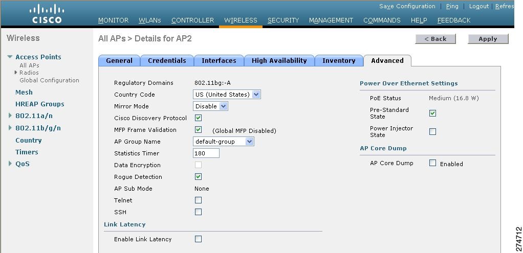
Step 1 Choose Wireless > Access Points > All APs to open the All APs page. Step 2 Click the name of the access point for which you want to enable Telnet or SSH. Step 3 Choose the Advanced tab to open the All APs > Details for (Advanced) page. Step 4 To enable Telnet connectivity on this access point, select the Telnet check box. The default value is unchecked. Step 5 To enable SSH connectivity on this access point, select the SSH check box. The default value is unchecked. Step 6 Click Apply to commit your changes. Step 7 Click Save Configuration to save your changes.
Troubleshooting Access Points Using Telnet or SSH (CLI)
Step 1 To enable Telnet or SSH connectivity on an access point, enter this command: config ap {telnet | ssh} enable Cisco_AP
The default value is disabled.
Note To disable Telnet or SSH connectivity on an access point, enter this command: config ap {telnet | ssh} disable Cisco_AP
Step 2 To save your changes, enter this command: Step 3 To see whether Telnet or SSH is enabled on an access point, enter this command: show ap config general Cisco_AP
Information similar to the following appears:
Cisco AP Identifier.............................. 5
Cisco AP Name.................................... AP33
Country code..................................... Multiple Countries:US,AE,AR,AT,AU,BH
Reg. Domain allowed by Country................... 802.11bg:-ABCENR 802.11a:-ABCEN
AP Country code.................................. US - United States
AP Regulatory Domain............................. 802.11bg:-A 802.11a:-A
Switch Port Number .............................. 2
MAC Address...................................... 00:19:2f:11:16:7a
IP Address Configuration......................... Static IP assigned
IP Address....................................... 10.22.8.133
IP NetMask....................................... 255.255.248.0
Gateway IP Addr.................................. 10.22.8.1
Domain...........................................
Name Server......................................
Telnet State..................................... Enabled
Ssh State........................................ Enabled
...
Managing the Controller Wirelessly
You can monitor and configure controllers using a wireless client. This feature is supported for all management tasks except uploads from and downloads to the controller.
Before you can open the GUI or the CLI from a wireless client device, you must configure the controller to allow the connection.