Cisco 5700 Series Wireless Controller Installation Guide
Available Languages
Table of Contents
Cisco 5700 Series Wireless Controller Installation Guide
Compliance and Safety Information
FCC Safety Compliance Statement
Statement 372—Wireless LAN Products
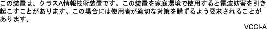
Statement 191—VCCI Class A Warning for Japan
10/100/1000 Ethernet Management Port
Unpacking and Installing the Controller
Required Tools and Information
Initial System Configuration Information
Attaching the Rack-Mount Brackets
Mounting the Controller in a Rack
Connecting the Controller’s Console Port
Verifying Interface Settings and Port Operation
Connecting the Console Port (Optional)
Installing or Replacing an AC Power Supp ly
Finding the Power Supply Module Serial Number
Finding the Fan Module Serial Number
Cisco 90-Day Limited Hardware Warranty Terms
Cisco 5700 Series Wireless Controllers SKU License
Obtaining Documentation and Submitting a Service Request
Cisco 5700 Series Wireless Controller Installation Guide
This guide is designed to help you install and minimally configure your Cisco 5700 Series Wireless Controller.
Compliance and Safety Information
FCC Safety Compliance Statement
Modifying the equipment without Cisco’s authorization may result in the equipment no longer complying with FCC requirements for Class A digital devices. In that event, your right to use the equipment may be limited by FCC regulations, and you may be required to correct any interference to radio or television communications at your own expense.
This equipment has been tested and found to comply with the limits for a Class A digital device, pursuant to Part 15 of the FCC Rules. These limits are designed to provide reasonable protection against harmful interference when the equipment is operated in a commercial environment. This equipment generates, uses, and can radiate radio frequency energy and, if not installed and used in accordance with the instruction manual, may cause harmful interference to radio communications. Operation of this equipment in a residential area is likely to cause harmful interference in which case users will be required to correct the interference at their own expense.
Try to correct the interference by one or more of the following measures:
- Verify that the ambient temperature remains between 32 to 104° F (0 to 40° C), taking into account the elevated temperatures when installed in a rack or enclosed space.
- When multiple Cisco 5700 Series Wireless Controllers are mounted in an equipment rack, be sure that the power source is sufficiently rated to safely run all the equipment in the rack.
- Verify the integrity of the electrical ground before installing the controller.
Safety Information
Safety warnings appear throughout this guide in procedures that may harm you if performed incorrectly. A warning symbol precedes each warning statement. The warnings below are general warnings that apply to the entire guide. Translated versions of the safety warnings in this guide are provided in the Regulatory Compliance and Safety Information for the Cisco 5700 Series Wireless Controller document that accompanies this guide.

Warning
IMPORTANT SAFETY INSTRUCTIONS
This warning symbol means danger. You are in a situation that could cause bodily injury. Before you work on any equipment, be aware of the hazards involved with electrical circuitry and be familiar with standard practices for preventing accidents. Use the statement number provided at the end of each warning to locate its translation in the translated safety warnings that accompanied this device. Statement 1071
SAVE THESE INSTRUCTIONS
Warning
Controller Overview
The Cisco 5700 Series Wireless Controller, designed for 802.11n/802.11ac performance and scalability, supports up to 1000 access points and 12000 clients, making it ideal for large-sized enterprises and high-density applications. A core component of the Cisco unified wireless solution, this controller delivers wireless security, intrusion detection, radio management, quality of service (QoS), and mobility across an entire enterprise. The controller works in conjunction with other controllers, Cisco Prime Infrastructure, and access points to provide network managers with a robust wireless LAN solution.
To best use this guide, you should have already designed the wireless topology of your network. Because the Radio Resource Management (RRM) feature automatically detects and configures access points as they appear on the network, it is not necessary to have any access points on the network in order to install and configure a controller.
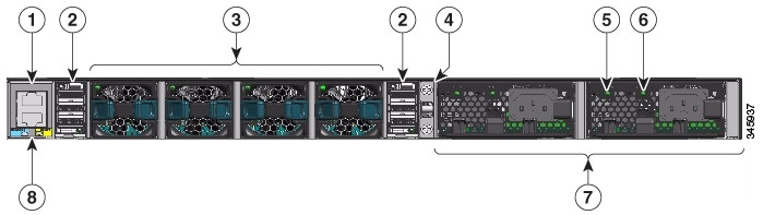
Figure 1 and Figure 2 show the front panel and back panel of the Cisco 5700 Series Wireless Controller.
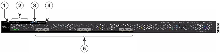
Port Connections
The controller has both EIA/TIA-232 asynchronous (RJ-45) and USB 5-pin mini Type B, 2.0 compliant serial console ports. The default parameters for the console ports are 9600 baud, 8 data bits, 1 stop bit, and no parity. The console ports do not support hardware flow control.
USB Type A Port
The USB Type A interface provides access to external USB flash devices (also known as thumb drives or USB keys).
The interface supports Cisco USB flash drives with capacities from 64 MB to 1 GB.
Cisco IOS software provides standard file system access to the flash device: read, write, erase, and copy, as well as the ability to format the flash device with a FAT file system.
USB Mini-B Console Port
The controller provides a USB mini-Type B console connection on the front panel, and an RJ-45 console port on the rear panel. Console output is always active on both connectors, but console input is active on only one connector at a time, with the USB connector taking precedence over the RJ-45 connector.
Use a USB type-A-to-USB 5-pin mini-Type B cable to connect a PC or other device to the controller.

Note
The connected device must include a terminal emulation application.The device can be a Linux, MacOS, or Windows device.
When the controller detects a valid USB connection to a powered device, input from the RJ-45 console port is immediately disabled, and the input from the USB console is enabled. Removing the USB connection immediately reenables input from the RJ-45 connection. An LED on the front panel is green when the USB console connection is enabled.
The controller provides a configurable inactivity timeout that reactivates the RJ-45 console if no input activity has occurred on the USB console for a specified time period. After the USB console has been deactivated due to a timeout, you can restore its operation by disconnecting and reconnecting the USB cable. You can disable USB console operation by using Cisco IOS commands. See the controller software configuration guide for details.
Note
When using the USB console port for operation with Microsoft Windows, you must install the Cisco Windows USB Console Driver on any PC that is connected to the console port. If it is not installed, prompts guide you through a simple installation process.
Note
To download the latest Cisco Windows USB Console Driver, follow these steps:
Step 1
Step 3
Step 4
Step 5
Step 6
1/10G SFP+ Ports
The SFP and SFP+ modules provide copper or fiber-optic connections to other devices. These transceiver modules are field-replaceable, providing the physical interfaces when installed in an SFP module slot. The SFP modules have LC connectors for fiber-optic connections or RJ-45 connectors for copper connections.
Use only Cisco SFP and SFP+ modules on the controller.
Warning
- Off—The link is down.
- Green—The link is up and there is no activity.
- Blinking green—The link is up and there is activity.
- Amber—The link is disabled.
- Blinking amber—The link is off due to a fault or because a user- configurable limit has been exceeded.
Supported Cisco SFP and SFP+ modules are listed in Table 1 and Table 2 .
Note
10/100/1000 Ethernet Management Port
You can connect the controller to a host such as a Windows workstation or a terminal server through the 10/100/1000 Ethernet management port. The 10/100/1000 Ethernet management port is a VPN routing/forwarding (VRF) interface and uses an RJ-45 crossover or straight-through cable.
Controller’s System LEDs
If your controller is not working properly, check the LEDs on the front panel of the unit. You can use the LED indications to quickly assess the unit’s status.
To select or change a mode, press the Mode button until the desired mode is highlighted. When you change modes, the meanings of the LED colors also change.
Table 3 explains how to interpret the LED colors in different modes.
Note
Unpacking and Installing the Controller
Follow these steps to unpack the Cisco 5700 Series Wireless Controller and prepare it for operation:
Step 1
Step 2
Step 3
Box Contents
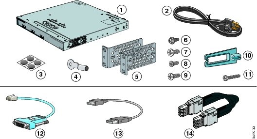
Cisco 5700 Series Wireless Controller (power supply and fan modules not shown)1
(Optional) RJ-45 console cable2
(Optional) USB console cable 2
(Optional) StackWise cable (0.5-meter, 1-meter, or 3-meter) 2
Note
Required Tools and Information
You will need the following equipment to install the controller:
–
–
–
–
- Local TFTP server (required for downloading operating system software updates). Cisco uses an integral TFTP server. This means that third-party TFTP servers cannot run on the same workstation as Cisco Prime Infrastructure because Cisco Prime Infrastructure and third-party TFTP servers use the same communication port.
You will need the following tools before you can install the controller:
The following additional items (not found in the accessory kit) are required to ground the chassis:
Initial System Configuration Information
Obtain the following initial configuration parameters from your wireless LAN or network administrator:
- A system (controller) name.
- The enable secret password.
- The enable password.
- Virtual terminal password.
- SNMP network management configuration information.
- Management network configuration information.
- NTP server information or current time.
- A Cisco wireless LAN controller mobility group name.
- The country code for this installation. Refer to the Cisco Wireless LAN Controller Configuration Guide for country code information. This guide is available at cisco.com.
- Wireless management interface configuration information.
Choosing a Physical Location
You can install the controller almost anywhere, but it is more secure and reliable if you install it in a secure equipment room or wiring closet. For maximum reliability, mount the controller using the following guidelines:
Warning
104° F (40° C) Statement 1047
Warning
4 in (10.16 cm) Statement 1076
- Make sure you can reach the controller and all cables attached to it.
- Make sure that water or excessive moisture cannot get into the controller.
- Make sure that the SFP and SFP+ Module Cable Specifications are met. Each port must match the wave-length specifications on each end of the cable, and the cable must not exceed the stipulated cable length. Copper 1000BASE-T SFP module transceivers use standard four twisted-pair, Category 5 cable at lengths up to 328 feet (100 meters).
Table 4 describes the SFP and SFP+ Module Cable Specifications.
Table 4 Fiber-Optic SFP and SFP+ Module Port Cabling Specifications
G.6524
722 feet (220 m)
902 feet (275 m)
1,640 feet (500 m)
1,804 feet (550 m)
32,810 feet (10 km)MMF5
SMF1,804 feet (550 m)
1,804 feet (550 m)
1,804 feet (550 m)
32,810 feet (10 km)43.4 to 62 miles
(70 to 100 km)63033, 3112, 3190, 3268, 3346, 3425, 3504, 3582, 3661, 3739, 3819, 3898, 3977, 4056, 4134, 4294, 4373, 4453, 4532, 4612, 4612, 4692, 4772, 4851, 4931, 5012, 5092, 5172, 5252, 5332, 5413, 5494, 5575, 5655, 5736, 5817, 5898, 5979, 6061, 6141
1804 feet (550 m) 1804 feet (550 m) 1804 feet (550 m)
6.2 miles (10 km)722 feet (220 m)
902 feet (275 m)
1640 feet (500 m)
1804 feet (550 m)85 feet (26 m)
108 feet (33 m)
216 feet (66 m)
269 feet (82 m)
6,561 feet (2000 m)Twinax cable, 30-AWG cable assembly
Installing the Chassis
The controller ships with rack mounting brackets and the desktop or shelf mounting rubber feet in a separate bag.
An adjustable rack-mount kit is included for mounting the controller in a standard 19-inch (48.3 cm) equipment rack. A standard equipment rack has two unobstructed outer posts, a minimum depth between the front and rear mounting posts of 13 inches (33 cm), and a maximum depth of 32 inches (81.3 cm).
You can also install the controller in a 2-post equipment rack.
This kit is not suitable for racks with obstructions (such as a power strip) that could impair access to system components.
Rack-Mounting
To install the controller in a 19-inch rack, follow the instructions described in this section.
The 19-inch brackets are included with the controller. Installing the controller in other rack types requires an optional bracket kit not included with the controller. Figure 3 shows the mounting brackets and part numbers.
Figure 3 Rack-Mounting Brackets

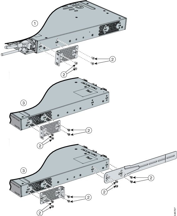
Attaching the Rack-Mount Brackets
To install the controller in a rack, use four Phillips flat-head screws to attach the long side of the brackets to the controller for the front- or rear-mounting positions (Figure 4). Use four screws to attach the brackets for the front-mounting position.
Figure 4 Attaching Brackets for 19-inch Racks
Mounting the Controller in a Rack
After the brackets are attached to the controller, use the supplied Phillips machine screws to attach the brackets to the rack (Figure 5). Use the black Phillips machine screw to attach the cable guide to the left or right bracket.
Figure 5 Mounting the Controller in a Rack

Table- or Shelf-Mounting
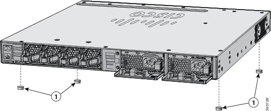
To install the controller on a table or shelf, locate the adhesive strip with the rubber feet in the mounting-kit envelope. Attach the four rubber feet to the recessed areas on the bottom of the chassis (see Figure 6).
Figure 6 Attaching the Adhesive Pads for Table- or Shelf-Mounting
Grounding the Chassis
Follow the grounding procedures at your site and observe these warnings:
Warning
Warning

Caution
Note
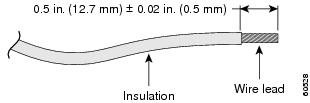
Follow these steps to install the grounding lug on the controller. Make sure to follow any grounding requirements at your site.
Step 1
Figure 7 Stripping the Ground Wire
Step 2
Step 3
Step 4
Step 5
a.
b.
Step 6
Step 7
Preventing ESD Damage
Electrostatic discharge (ESD) damage occurs when electronic cards or components are improperly handled and can result in complete or intermittent failures.
Always use an ESD-preventive wrist or ankle strap and ensure that it makes good skin contact. Connect the strap to any unpainted surface on the chassis.
Connecting the Controller’s Console Port
Before you can configure the controller for basic operations, you need to connect it to a PC that uses a VT-100 terminal emulator (such as HyperTerminal, ProComm, Minicom, or Tip).
Note
Note
Follow these steps to connect the PC to the controller’s console port:
Step 1
If you use the USB console port, plug the 5-pin mini Type B connector into the controller’s USB console port and the other end of the cable into the PC’s USB Type A port.
Step 2
Step 3
Using the Startup Wizard
Before you can use the startup wizard, you may need to obtain the information discussed in the “Required Tools and Information” section. Also, you will need to know the following information:
- Management network interface IP Address
- Wireless management interface IP Address
- VLAN number for the wireless management interface
At any point you may enter a question mark (?) for help. Press Ctrl-C to abort the configuration dialog at any prompt. Default settings are enclosed with square brackets ([]).
Basic management setup configures only enough connectivity for management of the system, extended setup will ask you to configure each interface on the system.
To configure the controller for basic operation using the Startup Wizard, follow these steps:
Step 1
Step 2
Step 3
Step 4
Step 5
Step 6
a.
b.
a.
b.
Step 7
Step 8
Step 9
Step 10
Step 11
For an example:a.
b.
c.
d.
Step 12
The wireless management interface must be configured at startup.
a.
b.
c.
Step 13
- 0—Go to the IOS command prompt without saving this config.
- 1—Return back to the setup without saving this config.
- 2—Save this configuration to nvram and exit.
Logging into the Controller
Follow these steps to log into the controller:
Step 1
Note
Step 2
The system prompt can be any alphanumeric string up to 31 characters. You can change it by entering the config prompt command.
Note
Note
Verifying Interface Settings and Port Operation
Follow these steps to verify that your interface configurations have been set properly and the controller’s ports are operational.
Step 1
Step 2
A link status of Up indicates that the controller’s ports are fully operational.
Connecting the Console Port (Optional)
The console port is controlled by the console-port interface and is reserved for out-of-band management of the controller and system recovery and maintenance in the event of a network failure. The console-port interface enables the controller to be managed on an interface different from the one used for your network traffic. Use of the console port is optional.
You can perform out-of-band controller management from a PC running a terminal emulation program or a PC running Cisco Prime infrastructure, a network management tool that enables you to configure and monitor a network of controllers, or the controller GUI. However, you must first connect the PC to the switch’s console port in one of two ways:
- Use an Ethernet cross-over cable to connect the PC directly to the switch’s console port.
- For a remote connection (using Telnet or SSH) through a dedicated management network, use a Category 5, Category 5e, Category 6, or Category 7 Ethernet cable to connect the management network to the controller’s console port and the appropriate cable to connect the PC to the management network.
Connecting Access Points
After you have configured the controller, use Category-5, Category-5e, Category-6, or Category-7 Ethernet cables to connect Cisco lightweight access points to the network.
After successful configuration, the controller is ready to accept Access Points connections. When it connects to an access point, it records the access-point MAC address in its database. The controller Radio Resource Management (RRM) feature then automatically configures the access point to start sending and allowing clients to associate.
You have prepared the controller for basic operation. Refer to the Cisco Wireless LAN Controller Configuration Guide, Release 6.0, for information on configuring the controller to meet the specific needs of your wireless network.
Power Supply Installation
The controller can be powered using one or two power supply units. When the controller is equipped with two power supply units, the power supplies are redundant. Either power supply continues to power the controller should the other power supply unit fail. Also, the power supplies are hot swappable; you do not need to remove power from the controller to replace a power supply.
One power supply unit is installed in slot 1 at the factory. You can order a second power supply unit and install it in slot 2.
The power supplies do not have an on/off switch and can only be powered down by removing AC input.
Note
Power Supply Module Overview
All power supply modules have internal fans. All controllers ship with a blank cover in the second power supply slot.
Table 5 describes the supported internal power supply module.
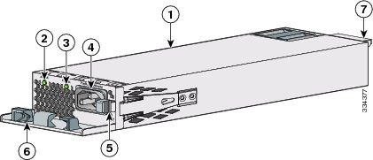
The 350-W AC power supply module is an autoranging unit that supports input voltages between 100 and 240 VAC.
The power supply module uses an 18- AWG power cord for connection to an AC power outlet.
Figure 9 350-W AC Power Supply Module
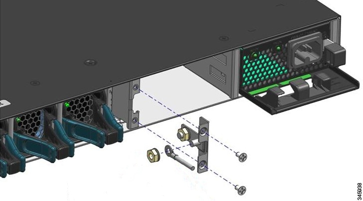
If no power supply is installed in a power supply slot, install a power supply slot cover (Figure 10).
Figure 10 Power Supply Slot Cover
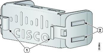
Table 6 describes the power supply modules status LEDs.
Installation Guidelines
Observe these guidelines when removing or installing a power supply or fan module:
- Do not force the power supply or fan module into the slot. This can damage the pins on the controller if they are not aligned with the module.
- A power supply that is only partially connected to the controller can disrupt the system operation.
- Remove power from the power-supply module before removing or installing the module.
Caution
Warning
Warning
Warning
Warning
Installing or Replacing an AC Power Supply
Step 1
Step 2
Step 3
Step 4
Caution
Warning
Step 5
Figure 11 Inserting the AC-Power Supply in the Controller
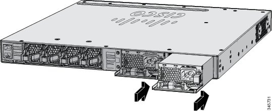
Step 6
Figure 12 AC-Power Supply with Power Cord Retainer
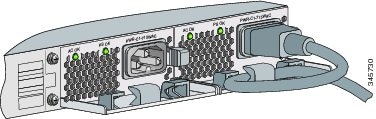
Step 7
Step 8
Finding the Power Supply Module Serial Number
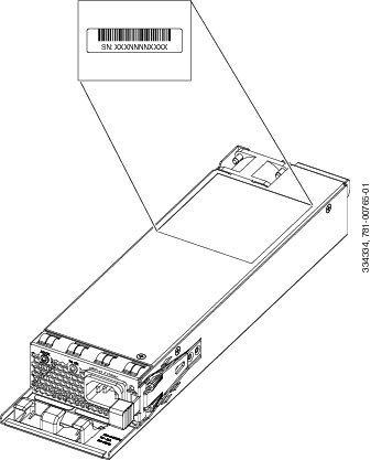
If you contact Cisco Technical Assistance regarding a power supply module, you need to know the serial number. See Figure 13 to find the serial number. You can also use the CLI to find out the serial number.
Figure 13 350-W AC Power Supply Module Serial Number
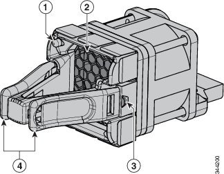
Installing a Fan Module
This section describes how to install a fan module.
The controller has four fan modules. Fan modules are hot-swappable. The controller can operate with one fan failure indefinitely, but the faulty fan should be replaced as soon as possible to avoid service disruption due to a second fan failure.
Fan Module Installation
Observe these guidelines when removing or installing a fan module:
- Do not force the fan module into the slot. This can damage the pins on the controller if they are not aligned with the module.
- A fan module that is only partially connected can disrupt the system operation.
- The controller supports hot swapping of the fan module. You can remove and replace the module without interrupting normal controller operation.
Warning
Step 1
Step 2
Warning
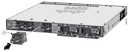
Figure 15 Installing the Fan Module
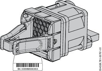
Finding the Fan Module Serial Number
If you contact Cisco Technical Assistance regarding a fan module, you need to know the fan module serial number. See Figure 16 for the serial number location.
Figure 16 Fan Module Serial Number
Specifications
Table 7 through Table 9 list the specifications for the controller and its power supply and fan modules.
Table 7 Environmental and Physical Specifications for the Cisco 5700 Series Wireless Controller
Operating7 temperature
Cisco 90-Day Limited Hardware Warranty Terms
There are special terms applicable to your hardware warranty and various services that you can use during the warranty period. Your formal Warranty Statement, including the warranties and license agreements applicable to Cisco software, is available on Cisco.com. Follow these steps to access and download the Cisco Information Packet and your warranty and license agreements from Cisco.com.
1.
http://www.cisco.com/c/en/us/products/warranty-listing.html
The Warranties and License Agreements page appears.
2.
a.
b.
The Cisco Limited Warranty and Software License page from the Information Packet appears.
d.
Note
3.
a.
b.
The Cisco warranty page appears.
d.
Click this link to browse to the Cisco Support and Documentation page:
http://www.cisco.com/cisco/web/support/index.html
Replacement, Repair, or Refund Policy for Hardware
Cisco or its service center will use commercially reasonable efforts to ship a replacement part within ten (10) working days after receipt of a Return Materials Authorization (RMA) request. Actual delivery times can vary, depending on the customer location.
Cisco reserves the right to refund the purchase price as its exclusive warranty remedy.
To Receive a Return Materials Authorization (RMA) Number
Contact the company from whom you purchased the product. If you purchased the product directly from Cisco, contact your Cisco Sales and Service Representative.
Complete the information below, and keep it for reference:
Cisco 5700 Series Wireless Controllers SKU License
There are special terms applicable when there is stacking of the Cisco 5700 Series Wireless Controllers.
The following table shows the examples of stacking of the controllers and its effect on the licenses for the Access Points (AP).
Table 10 Examples of stacking of the controllers & Licenses
Note
Related Documentation
Before installing or upgrading the controller, refer to the controller release notes.
http://www.cisco.com/c/en/us/support/wireless/5700-series-wireless-lan-controllers/tsd-products-support-series-home.html
http://www.cisco.com/c/en/us/support/interfaces-modules/transceiver-modules/tsd-products-support-series-home.html
http://www.cisco.com/c/en/us/solutions/enterprise/design-zone/index.html
Obtaining Documentation and Submitting a Service Request
For information on obtaining documentation, using the Cisco Bug Search Tool (BST), submitting a service request, and gathering additional information, see What’s New in Cisco Product Documentation at: http://www.cisco.com/c/en/us/td/docs/general/whatsnew/whatsnew.html.
Subscribe to What’s New in Cisco Product Documentation, which lists all new and revised Cisco technical documentation as an RSS feed and delivers content directly to your desktop using a reader application. The RSS feeds are a free service.

Cisco and the Cisco logo are trademarks or registered trademarks of Cisco and/or its affiliates in the U.S. and other countries. To view a list of Cisco trademarks, go to this URL: www.cisco.com/go/trademarks. Third-party trademarks mentioned are the property of their respective owners. The use of the word partner does not imply a partnership relationship between Cisco and any other company. (1110R)
Any Internet Protocol (IP) addresses and phone numbers used in this document are not intended to be actual addresses and phone numbers. Any examples, command display output, network topology diagrams, and other figures included in the document are shown for illustrative purposes only. Any use of actual IP addresses or phone numbers in illustrative content is unintentional and coincidental.


 Feedback
Contact Cisco
- Open a Support Case

- (Requires a Cisco Service Contract)