|
Table Of Contents
Nortel SL-100 Serial PIMG Integration Guide for Cisco Unity 4.0
Task List to Create the Integration
Integrations with Multiple Phone Systems
Planning How the Voice Messaging Ports Will Be Used by Cisco Unity
Programming the Nortel SL-100 Phone System
Creating a New Integration with the Nortel SL-100 Phone System
Integrating a Secondary Server for Cisco Unity Failover
Setting Up the Secondary Server for Failover
Appendix: Adding a Secondary Master PIMG UnitTask List to Add a Secondary Master PIMG Unit
Analog Voice Line Connections for the Master PIMG Units
Connections That Use RJ-11 Connectors
Serial Data Cable Connections for the Master PIMG Units
Connections for the Serial Data Cables
Configuring the Secondary Master PIMG Unit
Appendix: Using Alternate Extensions and MWIsSetting Up Alternate Extensions
Appendix: PIMG Integrations Over a WAN That Use the G.729a Codec May Need to Disable Comfort Noise
Appendix: Documentation and Technical AssistanceObtaining Documentation, Obtaining Support, and Security Guidelines
Nortel SL-100 Serial PIMG Integration Guide for Cisco Unity 4.0
Revised October 12, 2007
This document provides instructions for integrating the Nortel SL-100 phone system with Cisco Unity by using the PBX-IP Media Gateway (PIMG) and an RS-232 serial cable.
Integration Tasks
Before doing the following tasks to integrate Cisco Unity with the Nortel SL-100 phone system by using the PBX-IP Media Gateway (PIMG), confirm that the Cisco Unity server is ready for the integration by completing the applicable tasks in the applicable Cisco Unity installation guide.
The following task list describes the process for creating the integration.
Task List to Create the Integration
Use the following task list to set up a new integration with the Nortel SL-100 phone system. If you are installing a new Cisco Unity server by using the applicable Cisco Unity installation guide, you may have already completed some of the following tasks.
1. Review the system and equipment requirements to confirm that all phone system and Cisco Unity server requirements have been met. See the "Requirements" section.
2. Plan how the voice messaging ports will be used by Cisco Unity. See the "Planning How the Voice Messaging Ports Will Be Used by Cisco Unity" section.
3. Program the Nortel SL-100 phone system and extensions. See the "Programming the Nortel SL-100 Phone System" section.
4. Set up the PIMG units. See the "Setting Up the PIMG Units" section.
5. Create the integration. See the "Creating a New Integration with the Nortel SL-100 Phone System" section.
Caution Do not edit the phone configuration file (also known as the switch ini file) to customize this integration. If you change the settings in this file, the integration may not function correctly.
6. Test the integration. See the "Testing the Integration" section.
7. (Cisco Unity 4.1 and later) If you have a secondary server for Cisco Unity failover, integrate the secondary server. See the "Integrating a Secondary Server for Cisco Unity Failover" section.
Requirements
The Nortel SL-100 integration supports configurations of the following components:
Phone System
•The Nortel SL-100 phone system.
•Software version SE-06 or later.
•One or more of the applicable PIMG units. For details, refer to the "Supported Circuit-Switched Phone System Integrations" section in the applicable Supported Hardware and Software, and Support Policies at http://www.cisco.com/en/US/products/sw/voicesw/ps2237/prod_installation_guides_list.html.
•The serial data port on the phone system connected to the serial port on the master PIMG unit with an RS-232 serial cable.
We recommend that the serial cable have the following construction:
–A maximum of 50 feet (15.24 m) in length
–24 AWG stranded conductors
–Low capacitance—for example, no more than 12 pF/ft (39.4 pF/m) between conductors
–At least 65 percent braided shield over aluminized polymer sleeve around conductors
–UL-recognized overall cable jacket insulation with low dielectric constant
–Braided shield fully terminated to and enclosed by a metal connector backshell
–Gold-plated connector contacts
•The voice messaging ports in the phone system connected by analog lines to the ports on the PIMG units.
We recommend that you connect the voice messaging ports on the phone system to the ports on the PIMG units in a planned manner to simplify troubleshooting. For example, the first phone system voice messaging port connects to the first port on the first PIMG unit, the second phone system voice messaging port connects to the second port on the first PIMG unit, and so on.
•The PIMG units connected to the same LAN or WAN that Cisco Unity is connected to.
•If the PIMG units connect to a WAN, the requirements for the WAN network connections are:
–For G.729a codec formatting, a minimum of 32.76 Kbps guaranteed bandwidth for each voice messaging port.
Caution If you use G.729a codec formatting over a WAN and your PIMG units use firmware release 4 SU6 or earlier, you must disable comfort noise. Otherwise, callers will hear loud comfort noise at certain points. For details, see the "Appendix: PIMG Integrations Over a WAN That Use the G.729a Codec May Need to Disable Comfort Noise" section.
–For G.711 codec formatting, a minimum of 91.56 Kbps guaranteed bandwidth for each voice messaging port.
–No network devices that implement network address translation (NAT).
–A maximum 200 ms network latency.
•The phone system ready for the integration, as described in the documentation for the phone system.
Cisco Unity Server
•Cisco Unity installed and ready for the integration, as described in the applicable Cisco Unity installation guide at http://www.cisco.com/en/US/products/sw/voicesw/ps2237/prod_installation_guides_list.html.
•A license that enables the applicable number of voice messaging ports.
Integration Description
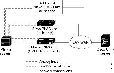
The Nortel SL-100 PIMG integration sends call information and MWI requests through the data link, which is an RS-232 serial cable that connects the phone system and the master PIMG unit. Voice connections are sent through the analog lines between the phone system to the PIMG units. The PIMG units communicate with the Cisco Unity server through the LAN or WAN by using Session Initiation Protocol (SIP). Figure 1 shows the required connections.
Figure 1 Connections Between the Phone System and Cisco Unity
Note You can add a secondary master PIMG unit. For details, see the "Appendix: Adding a Secondary Master PIMG Unit" section.
Call Information
The phone system sends the following information with forwarded calls:
•The extension of the called party
•The extension of the calling party (for internal calls) or the phone number of the calling party (if it is an external call and the system uses caller ID)
•The reason for the forward (the extension is busy, does not answer, or is set to forward all calls)
Cisco Unity uses this information to answer the call appropriately. For example, a call forwarded to Cisco Unity is answered with the personal greeting of the subscriber. If the phone system routes the call to Cisco Unity without this information, Cisco Unity answers with the opening greeting.
Note The Nortel SL-100 phone system also sends requests to turn on and turn off MWIs through the data link.
Integration Functionality
The Nortel SL-100 integration with Cisco Unity provides the following integration features:
•Call forward to personal greeting
•Call forward to busy greeting
•Caller ID
•Easy message access (a subscriber can retrieve messages without entering an ID because Cisco Unity identifies the subscriber based on the extension from which the call originated; a password may be required)
•Identified subscriber messaging (Cisco Unity identifies the subscriber who leaves a message during a forwarded internal call, based on the extension from which the call originated)
•Message waiting indication (MWI)
Integrations with Multiple Phone Systems
Depending on the version, Cisco Unity can be integrated with two or more phone systems:
•Cisco Unity 4.0 and 4.1 can be integrated with a maximum of two phone systems at one time. For information on and instructions for integrating Cisco Unity with two phone systems, refer to the Dual Phone System Integration Guide at http://www.cisco.com/en/US/products/sw/voicesw/ps2237/prod_configuration_guide09186a0080211b2e.html.
•Cisco Unity 4.2 and later can be integrated with two or more phone systems at one time. For information on the maximum supported combinations and instructions for integrating Cisco Unity with multiple phone systems, refer to the Multiple Phone System Integration Guide at http://www.cisco.com/en/US/products/sw/voicesw/ps2237/prod_configuration_guide09186a00806192a3.html.
Planning How the Voice Messaging Ports Will Be Used by Cisco Unity
Before programming the phone system, you need to plan how the voice messaging ports will be used by Cisco Unity. The following considerations will affect the programming for the phone system (for example, setting up the hunt group or call forwarding for the voice messaging ports):
•The number of voice messaging ports installed.
•The number of voice messaging ports that will answer calls.
•The number of voice messaging ports that will only dial out, for example, to send message notification, to set message waiting indicators (MWIs), to make AMIS deliveries, and to make telephone record and playback (TRAP) connections.
The following table describes the voice messaging port settings in Cisco Unity that can be set in UTIM, and that are displayed as read-only text on the System > Ports page of the Cisco Unity Administrator.
The Number of Voice Messaging Ports to Install
The number of voice messaging ports to install depends on numerous factors, including:
•The number of calls Cisco Unity will answer when call traffic is at its peak.
•The expected length of each message that callers will record and that subscribers will listen to.
•The number of subscribers.
•The number of ports that will be set to dial out only.
•The number of calls made for message notification.
•The number of MWIs that will be activated when call traffic is at its peak.
•The number of AMIS delivery calls.
•The number of TRAP connections needed when call traffic is at its peak. (TRAP connections are used by Cisco Unity web applications to play back and record over the phone.)
•The number of calls that will use the automated attendant and call handlers when call traffic is at its peak.
It is best to install only the number of voice messaging ports that are needed so that system resources are not allocated to unused ports.
The Number of Voice Messaging Ports That Will Answer Calls
The calls that the voice messaging ports answer can be incoming calls from unidentified callers or from subscribers. Typically, the voice messaging ports that answer calls are the busiest.
You can set voice messaging ports to both answer calls and to dial out (for example, to send message notifications). However, when the voice messaging ports perform more than one function and are very active (for example, answering many calls), the other functions may be delayed until the voice messaging port is free (for example, message notifications cannot be sent until there are fewer calls to answer). For best performance, dedicate certain voice messaging ports for only answering incoming calls, and dedicate other ports for only dialing out. Separating these port functions eliminates the possibility of a collision, in which an incoming call arrives on a port at the same time that Cisco Unity takes the port off-hook to dial out.
The Number of Voice Messaging Ports That Will Only Dial Out, and Not Answer Calls
Ports that will only dial out and will not answer calls can do one or more of the following:
•Notify subscribers by phone, pager, or e-mail of messages that have arrived.
•Turn MWIs on and off for subscriber extensions.
•Make outbound AMIS calls to deliver voice messages from Cisco Unity subscribers to users on another voice messaging system. (This action is available only with the AMIS licensed feature.)
•Make a TRAP connection so that subscribers can use the phone as a recording and playback device in Cisco Unity web applications.
Typically, these voice messaging ports are the least busy ports.
Caution In programming the phone system, do not send calls to voice messaging ports in Cisco Unity that cannot answer calls (voice messaging ports that are not set to Answer Calls). For example, if a voice messaging port is set only to Dialout MWI, do not send calls to it.
Preparing for Programming the Phone System
Record your decisions about the voice messaging ports to guide you in programming the phone system.
Programming the Nortel SL-100 Phone System
If you use programming options other than those supplied in the following procedure, the performance of the integration may be affected.
Caution In programming the phone system, do not send calls to voice messaging ports in Cisco Unity that cannot answer calls (voice messaging ports that are not set to Answer Calls). For example, if a voice messaging port is set only to Dialout MWI, do not send calls to it.
Do the following procedure.
Note All programming is accomplished through the maintenance administration position (MAP) terminal.
To Program the Nortel SL-100 Phone System
Step 1 On the MAP terminal, enter table mpc and press Enter.
Step 2 Enter add and press Enter.
Step 3 On Table MPC, enter the following settings.
Step 4 Enter table mpclink and press Enter.
Step 5 Enter add and press Enter.
Step 6 On Table MPCLINK, enter the following settings.
Step 7 Enter table sllnkdev and press Enter.
Step 8 Enter add and press Enter.
Step 9 On Table SLLNKDEV, enter the following settings.
Step 10 Enter table ofrt and press Enter.
You use Table OFRT to set up a treatment for unanswered calls. The following example shows settings for routing unanswered calls back to the voice messaging system.
Step 11 Enter add and press Enter.
Step 12 On Table OFRT, enter the following settings.
Step 13 Enter table digcol and press Enter.
You use Table DIGCOL to set up the action that the line module must take with the first digit that is dialed.
Step 14 Enter add and press Enter.
Step 15 On Table DIGCOL, enter the following settings.
Step 16 Enter table ucdgroup and press Enter.
You use Table UCDGRP to set up the UCD group.
Note The UCD group must have a unique primary DN.
Step 17 Enter add and press Enter.
Step 18 On Table UCDGRP, enter the following settings.
Step 19 Enter table dnroute and press Enter.
You use Table DNROUTE to set up the UCD group.
Note The UCD group must have a unique primary DN.
Step 20 Enter add and press Enter.
Step 21 On Table DNROUTE, enter the following settings.
Step 22 Enter table lninv and press Enter.
You use Table LNINV to assign card slots on the line or remote line module.
Step 23 Enter add and press Enter.
Step 24 On Table LNINV, enter the following settings.
Step 25 Enter servord and press Enter.
You will add agents to the UCD group by entering the following inputs at the prompts.
Step 26 Enter servord and press Enter.
You will add a pilot number (UCD group DN) for the ports on the PIMG units by entering the following inputs at the prompts.
Step 27 Connect a phone to the line.
Step 28 Pick up the handset.
Step 29 Dial the call forward activation code followed by the pilot number (UCD DN). For example, dial *80 5551234.
Note If you do not know this code, look it up in Table IBNXLA. The code is in the CFWP field.
Step 30 Confirm that you hear the confirmation tone, which indicates that the line has been forwarded.
Note If the phone system is restarted, you must repeat Step 27 through Step 30 for each line DN that CFUs to the UCD group.
Step 31 Enter table ibnxla and press Enter.
You use Table IBNXLA to set up and message waiting indicators (MWIs).
Step 32 Enter add and press Enter.
Step 33 On Table IBNXLA, enter the following settings.
Step 34 On each subscriber phone, program the phone to forward calls to the pilot number assigned to the voice messaging ports, based on one of the Cisco Unity call transfer types shown in Table 13.
Note You can use alternate extensions to create multiple line appearances, enable easy message access from cell phones, and simplify addressing messages to subscribers at different locations in Cisco Unity. Enabling alternate MWIs allows Cisco Unity to turn MWIs on at more than one extension. For details, see the "Appendix: Using Alternate Extensions and MWIs" section.
Setting Up the PIMG Units
Do the following procedures to set up the PIMG units that are connected to the Nortel SL-100 phone system.
These procedures require that the following tasks have already been completed:
•The phone system is connected to the PIMG units by using analog lines and the applicable RS-232 serial cable.
•The PIMG units are ready to be connected to the LAN or WAN.
•The PIMG units are connected to a power source.
Fields that are not mentioned in the following procedures must keep their default values. For the default values of all fields, see the documentation for the PIMG unit.
To Download the PIMG Firmware Update Files for Analog PIMG Units
Step 1 On a Windows workstation that will have access to the PIMG units, open a web browser and go to the Cisco Unity PIMG Software Download page at http://www.cisco.com/pcgi-bin/tablebuild.pl/unity-PIMG.
Note To access the software download page, you must be logged on to Cisco.com as a registered user.
Step 2 On the Cisco Unity PIMG Software Download page, click the most recent version of the firmware for analog PIMG units.
Step 3 On the Details page, click Next.
Step 4 On the Document page, click Accept.
Step 5 In the Enter Network Password dialog box, enter your user name and password, then click OK.
Step 6 In the File Download dialog box, click Save.
Step 7 In the Save As dialog box, browse to the Windows workstation that will have access the PIMG units, browse to a directory where you want to save the file, and click Save.
Step 8 In the Download Complete dialog box, click Open. The window for extracting the PIMG firmware update files appears.
Step 9 Click Extract.
Step 10 In the Extract dialog box, browse to the directory where you want the extracted files, and click Extract.
Step 11 Close the window for the extracting application.
To Set Up the Analog PIMG Units
Step 1 On the Windows workstation, add a temporary route to enable access to the PIMG units.
a. On the Windows Start menu, click Run.
b. Enter cmd, and press Enter. The Command Prompt window appears.
c. At the command prompt, enter route add 10.12.13.74 <IP Address of Workstation>, and press Enter.
For example, if the IP address of the workstation is 198.1.3.25, enter "route add 10.12.13.74<space>198.1.3.25" in the Command Prompt window.
d. Close the Command Prompt window.
Step 2 Connect a PIMG unit to the network.
Step 3 In the web browser, go to http://10.12.13.74.
Step 4 On the System Login page, enter the following case-sensitive settings.
Step 5 Click Log On.
Step 6 On the Configure menu, click Upgrade.
Step 7 On the Upgrade page, click Browse.
Step 8 In the Choose File dialog box, browse to the directory on the Windows workstation that has the extracted PIMG firmware update files.
Step 9 Click Ls_<xx>.app (where <xx> is multiple digits), and click Open.
Step 10 On the Upgrade page, click Install.
Step 11 After the file is installed, a message prompting you to restart the PIMG unit appears. Click Cancel.
Caution Do not restart the PIMG unit until you are instructed to do so later in this procedure, even if the file installation fails. Restarting the PIMG unit at this step may prevent the PIMG unit from functioning correctly.
Step 12 Repeat Step 6 through Step 11 for the file Run_<xx>.dsp.
Step 13 On the Configure menu, click Upgrade.
Step 14 On the Upgrade page, under Import, click Browse.
Step 15 In the Choose File dialog box, browse to the file Ls_<xx>.fsh.
Step 16 Click Ls_<xx>.fsh, and click Open.
Step 17 On the Upgrade page, click Install.
Step 18 After the file is installed, a message prompting you to restart the PIMG unit appears. Click OK.
Step 19 In the web browser, go to http://10.12.13.74.
Step 20 On the System Login page, enter the following case-sensitive settings.
Step 21 Click Log On.
Step 22 On the Configure menu, click Password.
Step 23 On the Password page, enter the following settings.
Step 24 Click Change.
Step 25 On the Configure menu, click System.
Step 26 On the System page, enter the following settings.
Table 17 System Page Settings
Field SettingOperating Mode
SIP
Telephony Switch Type
None
PCM Coding
uLaw
Step 27 Click Apply Changes.
Step 28 On the Configure menu, click Serial Protocol.
Step 29 On the Serial Protocol page, enter the following settings.
Step 30 Click Apply Changes.
Step 31 On the Configure menu, click Gateway.
Step 32 On the Gateway page, click the Gateway Routing tab.
Step 33 On the Gateway Routing tab, enter the following settings.
Step 34 Click Apply Changes.
Step 35 Click the Gateway Advanced tab.
Step 36 On the Gateway Advanced tab, enter the following settings.
Table 20 Gateway Advanced Tab Settings
Field SettingCall Connect Mode
OnAnswer
Destination for Unroutable IP Calls
<blank>
Destination for Unroutable PBX Calls
<blank>
Monitor Call Connections
No
Maximum Call Party Delay (msecs)
2000
Dial Digit on Time (msecs)
100
Dial Inter-Digit Time (msecs)
100
Dial Pause Time (msecs)
2000
Turn MWI On FAC
<blank>
Turn MWI Off FAC
<blank>
Outbound Call Connect Timeout (msecs)
10000
Wait for Ringback/Connect on Blind Transfer
No
Hunt Group Extension
<the pilot number for the Cisco Unity voice messaging ports>
Audio Compression
Click the preferred codec for audio compression:
•G.711 Only
•G.729 A Preferred
RTP Digit Relay Mode
RFC2833
Signaling Digit Relay Mode
Off
Voice Activity Detection
Off
Frame Size
Click the applicable setting:
•G.711—20
•G.729a—10
Caution Failure to use the correct setting will result in recorded messages containing nothing but silence.
Frames Per Packet
Click the applicable setting:
•G.711—1
•G.729a—2
Caution Failure to use the correct setting will result in recorded messages containing nothing but silence.
Call Control QOS Byte
(PIMG units connect only to a LAN) 0
(PIMG units connect to a WAN) 104
Note For details on the setting for a LAN, see the caveat CSCsb96387.
RTP QOS Byte
(PIMG units connect only to a LAN) 0
(PIMG units connect to a WAN) 184
Note For details on the setting for a LAN, see the caveat CSCsb96387.
SNMP Traps Enabled
No
E-mail Alarms Enabled
No
Step 37 Click Apply Changes.
Step 38 Click the Gateway Capabilities tab.
Step 39 Depending on how you have planned to use the voice messaging ports, click the applicable setting for each port in the Telephony Port Capability column.
Caution In setting up the PIMG unit, do not send calls to ports in Cisco Unity that cannot answer calls (voice messaging ports that are not set to Answer Calls). For example, if a voice messaging port is set only to Dialout MWI, do not send calls to it. Otherwise the integration will not function correctly.
If a port in Cisco Unity is disabled, click No in the Telephony Port Enabled column for the corresponding port on this tab. Note that changing a setting in the Telephony Port Enabled column requires restarting the PIMG unit.
Step 40 Click Apply Changes.
Step 41 On the Configure menu, click SIP.
Step 42 On the SIP page, enter the following settings.
Step 43 Click Apply Changes.
Step 44 On the Configure menu, click IP.
Step 45 On the IP page, enter the following settings.
Step 46 Click Apply Changes.
Step 47 On the Configure menu, click Tones.
Step 48 On the Tones page, click the Learn tab.
Caution Destination addresses cannot be duplicated in the same session. Otherwise, the process for learning tones will not succeed. If you do not have enough available phones to learn all the tones at one time, you can run multiple sessions to learn tones individually by checking or unchecking the applicable Acquire Tone check boxes.
Step 49 On the Tones page, for the Dialtone event, confirm that the Acquire Tone check box is checked and leave the Destination Address field blank.
Step 50 On the Tones page, for the Busy Tone event, confirm that the Acquire Tone check box is checked and do the following substeps to verify that the tone is correct.
a. From a available phone, call a second phone.
b. Answer the second phone when it rings, and leave both handsets off so that both phones are busy.
c. From a third phone, dial one of the busy phones.
d. Confirm that you hear a busy tone.
e. Hang up the third phone but leave the handsets for the other two phones off.
Step 51 On the Tones page, in the Destination Address field for Busy Tone, enter the extension that you dialed in Step 50c. from the third phone.
Step 52 On the Tones page, for the Error/Reorder Tone event, confirm that the Acquire Tone check box is checked and do the following substeps to verify that the tone is correct.
a. From an available phone, dial an extension that does not exist.
b. Confirm that you hear the reorder or error tone.
c. Hang up the phone.
Step 53 On the Tones page, in the Destination Address field for Error/Reorder Tone, enter the extension that you dialed in Step 52a.
Step 54 On the Tones page, for the Ringback Tone event, confirm that the Acquire Tone check box is checked and do the following substeps to verify that the tone is correct.
a. From an available phone, dial an extension that does exist
b. Confirm that you hear the ringback tone.
c. Hang up the phone.
Step 55 On the Tones page, in the Destination Address field for Ringback Tone, enter the extension that you dialed in Step 54a.
Step 56 Click Learn.
Note When running learn tones, the PIMG unit will restart after learning the first tone. For details, see the caveat CSCsh53791.
Step 57 When the process is complete, check the check box for each newly learned tone and click Apply.
Step 58 Hang up the phones that you used in Step 50.
Step 59 On the Configure menu, click Restart.
Step 60 On the Restart page, click Restart Unit Now.
Step 61 When the PIMG unit has restarted, in the View menu, click Refresh.
Step 62 Repeat Step 2 through Step 61 on all remaining PIMG units.
If your Cisco Unity system must have an RTP port range of 16384 to 32767, do the following procedure.
Note The default RTP port range for PIMG units is 49000 to 50000. Some Cisco Unity configurations require a different RTP port range.
To Set the RTP Port Range for PIMG Units
Step 1 On a Windows workstation that has access to the PIMG units, open a web browser and browse to the first PIMG unit.
Step 2 On the System Login page, log on to the PIMG unit.
Step 3 On the Configure menu, click Import/Export.
Step 4 On the Import/Export page, under Export Settings, click Export Settings.
Step 5 In the File Download dialog box, click Save.
Step 6 In the Save As dialog box, browse to the Windows workstation that has access to the PIMG units, browse to a directory where you want to save the file, and click Save.
Step 7 In the Download Complete dialog box, click Open. Notepad opens the file Config.ini that you saved.
Step 8 Locate the line with the following parameter:
gwRTPStartPortStep 9 Change the value of the parameter to 16384 so that the line reads as follows:
gwRTPStartPort = 16384Step 10 Locate the line with the following parameter:
gwRTPEndPortStep 11 Change the value of the parameter to 32767 so that the line reads as follows:
gwRTPEndPort = 32767Step 12 Save the file, and exit Notepad.
Step 13 On the Configure menu of the PIMG unit, click Import/Export.
Step 14 On the Import/Export page, under Import Settings, click Browse.
Step 15 In the Choose File dialog box, browse to the file Config.ini that you saved.
Step 16 Click Config.ini, and click Open.
Step 17 On the Import/Export page, click Import Settings.
Step 18 When prompted to restart the PIMG unit, click OK.
Step 19 Repeat this procedure for all remaining PIMG units.
Creating a New Integration with the Nortel SL-100 Phone System
After ensuring that the Nortel SL-100 phone system and the Cisco Unity server are ready for the integration, do the following procedures to set up the integration and to enter the port settings.
To Create an Integration
Step 1 If UTIM is not already open, on the Windows Start menu of the Cisco Unity server, click Programs > Cisco Unity > Manage Integrations. UTIM appears.
Step 2 In the left pane of the UTIM window, click Cisco Unity Server.
Step 3 On the Integration menu of the UTIM window, click New. The Telephony Integration Setup Wizard appears.
Step 4 On the Welcome page, click Circuit-switched via Intel PIMG and click Next.
Step 5 On the Name the Phone System Integration page, accept the default name or enter the phone system name to identify this integration, then click Next.
Step 6 On the Enter PIMG Settings page, click Add.
Step 7 In the Add PIMG dialog box, enter the following settings, then click OK.
Step 8 Repeat Step 6 and Step 7 for each remaining PIMG unit that you are connecting to the Cisco Unity server.
You can press the following buttons to modify, delete, or verify the PIMG units that you are connecting to the Cisco Unity server.
Step 9 On the Enter PIMG Settings page, click Next.
Step 10 On the PIMG Integration with the PBX page, click Yes.
Step 11 In the This PIMG Is the Serial Master field, click the name of the PIMG unit that is connected to the serial cable from the phone system, then click Next.
Step 12 On the Configure Cisco Unity SIP Settings page, enter the following settings, then click Next.
Step 13 If other integrations already exist, the Enter Trunk Access Code page appears. Enter the extra digits that Cisco Unity must use to transfer calls through the gateway to extensions on the other phone systems with which it is integrated. Then click Next.
Step 14 (Cisco Unity 4.2 and later only) On the Reassign Subscribers page, any subscribers whose phone system integration has been deleted and who are not currently assigned to a phone system integration will appear in the list.
If no subscribers appear in the list, click Next and continue to Step 15.
Otherwise, select the subscribers that you want to assign to this phone system integration and click Next. You can use the following selection controls for selecting subscribers.
Step 15 (Cisco Unity 4.2 and later only) On the Reassign Call Handlers page, any call handlers whose phone system integration has been deleted and that are not currently assigned to a phone system integration will appear in the list.
If no call handlers appear in the list, click Next and continue to Step 16.
Otherwise, select the call handlers that you want to assign to this phone system integration and click Next. You can use the following selection controls for selecting call handlers.
Step 16 On the Completing page, verify the settings you entered, then click Finish.
Step 17 At the prompt to restart the Cisco Unity services, click Yes. The Cisco Unity services restart.
Alternatively, you can restart the Cisco Unity services in UTIM on the Tools menu by clicking Restart Cisco Unity.
To Enter the Voice Messaging Port Settings for the Integration
Step 1 After the Cisco Unity services restart, on the View menu, click Refresh.
Step 2 In the left pane of the UTIM window, expand the phone system integration that you are creating.
Step 3 In the left pane, click the name of the first PIMG unit.
Step 4 In the right pane, click the Ports tab.
Step 5 Enter the settings shown in Table 29 for the voice messaging ports.
For best performance, use the first voice messaging ports for incoming calls and the last ports to dial out. This helps minimize the possibility of a collision, in which an incoming call arrives on a port at the same time that Cisco Unity takes the port off-hook to dial out.
Caution In programming the phone system, do not send calls to voice messaging ports in Cisco Unity that cannot answer calls (voice messaging ports that are not set to Answer Calls). For example, if a voice messaging port is set only to Message Notification, do not send calls to it.
Step 6 Click Save.
Step 7 Click the SIP Info tab.
Step 8 (Cisco Unity 4.2 and later) Uncheck the Register with SIP Server check box and click Save.
(Cisco Unity 4.0 and 4.1) Uncheck the Register with Proxy Server check box and click Save.
Step 9 At the prompt to restart the Cisco Unity services, click No.
Step 10 Repeat Step 3 through Step 9 for all remaining PIMG units.
Step 11 In the left pane, click Properties for the phone system.
Step 12 In the right pane, click the PIMG tab.
Step 13 Under Set Messaging Waiting Indicators (MWI) Using This Method, confirm that the Out-of-Band - SIP NOTIFY option is selected.
Step 14 Click Save.
Step 15 At the prompt to restart the Cisco Unity services, click Yes.
Step 16 After the Cisco Unity services restart, exit UTIM.
Note Do not edit the phone configuration file (also known as the switch ini file) to customize this integration. If you change the settings in this file, the integration may not function correctly.
Testing the Integration
To test whether Cisco Unity and the phone system are integrated correctly, do the following procedures in the order listed.
If any of the steps indicate a failure, refer to the following documentation as applicable:
•The installation guide for the phone system.
•Cisco Unity Troubleshooting Guide, available at http://www.cisco.com/en/US/products/sw/voicesw/ps2237/prod_troubleshooting_guides_list.html.
•The setup information earlier in this guide.
To Set Up the Test Configuration
Step 1 Set up two test extensions (Phone 1 and Phone 2) on the same phone system that Cisco Unity is connected to.
Step 2 Set Phone 1 to forward calls to the Cisco Unity pilot number when calls are not answered.
Caution The phone system must forward calls to the Cisco Unity pilot number in no fewer than four rings. Otherwise, the test may fail.
Step 3 In the Cisco Unity Administrator, create a test subscriber to use for testing by doing the applicable substeps below.
If your message store is Microsoft Exchange, do the following:
a. In the Cisco Unity Administrator, go to the Subscribers > Subscribers > Profile page.
b. Click the Add icon.
c. Select New Exchange Subscriber.
d. On the Add Subscriber page, enter the applicable information.
e. Click Add.
If your message store is IBM Lotus Domino, do the following:
a. In the Cisco Unity Administrator, go to the Subscribers > Subscribers > Profile page.
b. Click the Add icon.
c. Click Notes.
d. In the Address Book list, confirm that the address book listed is the one that contains the user data that you want to import.
If the address book that you want to use is not listed, go to the System > Configuration > Subscriber Address Books page and add a different address book.
e. In the Find Domino Person By list, indicate whether to search by short name, first name, or last name.
f. Enter the applicable short name or name. You also can enter * to display a list of all users, or enter one or more characters followed by * to narrow your search.
g. Click Find.
h. On the list of matches, click the name of the user to import.
i. On the Add Subscriber page, enter the applicable information.
j. Click Add.
Step 4 In the Extension field, enter the extension of Phone 1.
Step 5 In the Active Schedule field, click All Hours - All Days.
Step 6 Click the Save icon.
Step 7 In the navigation bar, click Call Transfer to go to the Subscribers > Subscribers > Call Transfer page for the test subscriber.
For more information on transfer settings, refer to the "Subscriber Template Call Transfer Settings" section in the Cisco Unity Administrator Help.
Step 8 Under Transfer Incoming Calls, click Yes, Ring Subscriber's Extension, and confirm that the extension number is for Phone 1.
Step 9 Under Transfer Type, click Release to Switch.
Step 10 Click the Save icon.
Step 11 In the navigation bar, click Messages to go to the Subscribers > Subscribers > Messages page for the test subscriber.
Step 12 Under Message Waiting Indicators (MWIs), check Use MWI for Message Notification.
Step 13 In the Extension field, enter x.
Step 14 Click the Save icon.
Step 15 Open the Status Monitor by doing one of the following:
•In Internet Explorer, go to http://<Cisco Unity server name>/web/sm.
•Double-click the desktop shortcut to the Status Monitor.
•In the status bar next to the clock, right-click the Cisco Unity tray icon and click Status Monitor.
To Test an External Call with Release Transfer
Step 1 From Phone 2, enter the access code necessary to get an outside line, then enter the number outside callers use to dial directly to Cisco Unity.
Step 2 On the Status Monitor, note which port handles this call.
Step 3 When you hear the opening greeting, enter the extension for Phone 1. Hearing the opening greeting means that the port is configured correctly.
Step 4 Confirm that Phone 1 rings and that you hear a ringback tone on Phone 2. Hearing a ringback tone means that Cisco Unity correctly released the call and transferred it to Phone 1.
Step 5 Leaving Phone 1 unanswered, confirm that the state of the port handling the call changes to "Idle." This state means that release transfer is successful.
Step 6 Confirm that, after the number of rings that the phone system is set to wait, the call is forwarded to Cisco Unity and that you hear the greeting for the test subscriber. Hearing the greeting means that the phone system forwarded the unanswered call and the call-forward information to Cisco Unity, which correctly interpreted the information.
Step 7 On the Status Monitor, note which port handles this call.
Step 8 Leave a message for the test subscriber and hang up Phone 2.
Step 9 On the Status Monitor, confirm that the state of the port handling the call changes to "Idle." This state means that the port was successfully released when the call ended.
Step 10 Confirm that the MWI on Phone 1 is activated. The activated MWI means that the phone system and Cisco Unity are successfully integrated for turning on MWIs.
To Test Listening to Messages
Step 1 From Phone 1, enter the internal pilot number for Cisco Unity.
Step 2 When asked for your password, enter the default password. Hearing the request for your password means that the phone system sent the necessary call information to Cisco Unity, which correctly interpreted the information.
Step 3 Confirm that you hear the recorded voice name for the test subscriber (if you did not record a voice name for the test subscriber, you will hear the extension number for Phone 1). Hearing the voice name means that Cisco Unity correctly identified the subscriber by the extension.
Step 4 When asked whether you want to listen to your message, press 1.
Step 5 After listening to the message, press 3 to delete the message.
Step 6 Confirm that the MWI on Phone 1 is deactivated. The deactivated MWI means that the phone system and Cisco Unity are successfully integrated for turning off MWIs.
Step 7 Hang up Phone 1.
Step 8 On the Status Monitor, confirm that the state of the port handling the call changes to "Idle." This state means that the port was successfully released when the call ended.
To Set Up Supervised Transfer on Cisco Unity
Step 1 In the Cisco Unity Administrator, go to the Subscribers > Subscribers > Call Transfer page.
If the name of the test subscriber is not displayed, click the Find icon (the magnifying glass) in the title bar, then click Find, and select the name of the test subscriber in the list that appears.
For more information on transfer settings, refer to the "Subscriber Template Call Transfer Settings" section in the Cisco Unity Administrator Help.
Step 2 Under Transfer Type, click Supervise Transfer.
Step 3 Set the Rings to Wait For field to 3.
Step 4 Click the Save icon.
To Test Supervised Transfer
Step 1 From Phone 2, enter the access code necessary to get an outside line, then enter the number outside callers use to dial directly to Cisco Unity.
Step 2 On the Status Monitor, note which port handles this call.
Step 3 When you hear the opening greeting, enter the extension for Phone 1. Hearing the opening greeting means that the port is configured correctly.
Step 4 Confirm that Phone 1 rings and that you do not hear a ringback tone on Phone 2. Instead, you should hear the indication your phone system uses to mean that the call is on hold (for example, music or beeps).
Step 5 Leaving Phone 1 unanswered, confirm that the state of the port handling the call remains "Busy." This state and hearing an indication that you are on hold mean that Cisco Unity is supervising the transfer.
Step 6 Confirm that, after three rings, you hear the greeting for the test subscriber. Hearing the greeting means that Cisco Unity successfully recalled the supervised-transfer call.
Step 7 During the greeting, hang up Phone 2.
Step 8 On the Status Monitor, confirm that the state of the port handling the call changes to "Idle." This state means that the port was successfully released when the call ended.
To Delete the Test Subscriber
Step 1 In the Cisco Unity Administrator, go to the Subscribers > Subscribers > Profile page.
If the name of the test subscriber is not displayed, click the Find icon (the magnifying glass) in the title bar, then click Find, and select the name of the test subscriber in the list that appears.
Step 2 In the title bar, click the Delete Subscriber icon (the X).
Step 3 Click Delete.
Integrating a Secondary Server for Cisco Unity Failover
For Cisco Unity 4.1 and later, the Cisco Unity failover feature enables a secondary server to provide voice messaging services when the primary server becomes inactive. For information on installing a secondary server for failover, refer to the applicable Cisco Unity installation guide, available at http://www.cisco.com/en/US/products/sw/voicesw/ps2237/prod_installation_guides_list.html.
The Cisco Unity failover feature is not available when this phone system is integrated with Cisco Unity 4.0 through PIMG units.
For information on failover, refer to the Cisco Unity Failover Configuration and Administration Guide. The Domino version of the guide is available at http://www.cisco.com/en/US/products/sw/voicesw/ps2237/products_feature_guide_book09186a00803f70f3.html. The Exchange version of the guide is available at http://www.cisco.com/en/US/products/sw/voicesw/ps2237/products_feature_guide_book09186a00801b9241.html.
Requirements
The following components are required to integrate a secondary server:
•One secondary server for each primary server installed and ready for the integration, as described in the applicable Cisco Unity installation guide and earlier in this integration guide.
•A license that enables failover.
Integration Description
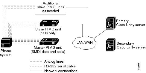
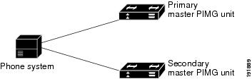
The Nortel SL-100 phone system sends call information and MWI requests through the data link, which consists of an RS-232 serial cable between the phone system and the master PIMG unit. Voice connections are sent through the analog lines between the phone system and the PIMG units. The PIMG units communicate with the primary and secondary servers through the LAN or WAN by using Session Initiation Protocol (SIP). Figure 2 shows the required connections.
Figure 2 Connections Between the Phone System and the Cisco Unity Servers
The primary and secondary servers act in the following manner:
•When the primary server is operating normally, the secondary server is inactive.
•When the primary server becomes inactive, the secondary server becomes active.
•When the primary server becomes active again, the secondary server becomes inactive.
Setting Up the Secondary Server for Failover
Do the following procedure to integrate the secondary server.
To Set Up the Secondary Server for Failover
Step 1 Install a secondary server with the same configuration as the primary server. For installation instructions, refer to the applicable Cisco Unity installation guide.
Step 2 On the Windows Start menu of the secondary server, click Programs > Cisco Unity > Manage Integrations. The UTIM window appears.
Step 3 On the Integration menu of the UTIM window, click New. The Telephony Integration Setup Wizard appears.
Step 4 Enter the settings to match the integration settings on the primary server.
Note We recommend not reassigning any unassigned subscribers and call handlers to the new integration, if you are asked by the wizard. Failover replication will automatically assign the correct integration.
Step 5 At the prompt to restart the Cisco Unity services, click Yes.
Note When restarting the Cisco Unity services, use the UTIM prompt instead of the Cisco Unity icon in the Windows taskbar. The taskbar icon does not restart all of the Cisco Unity services.
Step 6 After Cisco Unity restarts, on the Windows Start menu of the Cisco Unity server, click Programs > Cisco Unity > Manage Integrations. UTIM appears.
Step 7 In the left pane of the UTIM window, click the phone system integration that you created in Step 3.
Step 8 For Cisco Unity 4.0 and 4.1, continue to Step 9.
For Cisco Unity 4.2 and later, do the following substeps.
a. In the right pane, click Properties.
b. On the Integration tab, compare the setting of the Integration ID field for the secondary server to the setting of the Integration ID field for the primary server.
c. If the integration IDs of the phone system on the primary and secondary server are the same, continue to Step 9.
If the integration IDs of the phone system on the primary and secondary servers are different, on the secondary server, click Modify Integration ID.
d. When cautioned that subscribers associated with the current Integration ID setting will not be automatically associated with the new Integration ID setting, click OK.
e. In the Modify Integration ID dialog box, in the Enter New Integration ID field, enter the Integration ID setting for the phone system on the primary server and click OK.
f. Click Save.
g. At the prompt to restart the Cisco Unity services, click Yes.
h. In the left pane, click the phone system integration that you created in Step 3.
Step 9 In the right pane, click the Ports tab.
Step 10 Enter the port settings to match the port settings on the primary server.
Caution In programming the phone system, do not send calls to voice messaging ports in Cisco Unity that cannot answer calls (voice messaging ports that are not set to Answer Calls). For example, if a voice messaging port is set only to Message Notification, do not send calls to it.
Step 11 Click Save.
Step 12 Repeat Step 9 through Step 11 for each remaining PIMG unit in the phone system integration.
Step 13 Exit UTIM.
Appendix: Adding a Secondary Master PIMG Unit
Because the master PIMG unit processes all call information and MWI requests for the system, the integration will lose important functionality if the master PIMG unit stops working. If you want to minimize this risk, you can add a secondary master PIMG unit to process call information and MWI requests when the primary master PIMG unit is no longer functioning.
During normal operation, the primary master PIMG unit is connected to power and is functioning, while the secondary master PIMG unit is not connected to power and is not functioning. To activate the secondary master PIMG unit, you must disconnect power to the primary master PIMG unit, then connect power to the secondary master PIMG unit.
The following task list describes the process for adding a secondary master PIMG unit.
Task List to Add a Secondary Master PIMG Unit
Use the following task list to add a secondary master PIMG unit.
1. Set up the analog voice line connections to the master PIMG units. See the "Analog Voice Line Connections for the Master PIMG Units" section.
2. Set up the serial data cable connections to the master PIMG units. See the "Serial Data Cable Connections for the Master PIMG Units" section.
3. Configure the secondary master PIMG unit. See the "Configuring the Secondary Master PIMG Unit" section.
Analog Voice Line Connections for the Master PIMG Units
Circuit-switched phone systems typically have 25-pair or 32-pair cables to provide analog voice connections. It is common that the cable is broken into individual lines that may attach to a punchdown cross-connect block (for example, 66-Type), or the cable may terminate with RJ-11 or RJ-14 connectors to accept analog voice lines.
A punchdown cross-connect block or line splitters may be used to split the analog lines. It is possible to use these devices in combination to manage and split the lines.
Note No devices other than those described in this appendix should be connected to the analog voice lines for any voice messaging port on the master PIMG units. Otherwise, the ring equivalency number (REN) may be exceeded and the primary and secondary servers may not receive sufficient ring current to answer calls.
Requirements
The following components are required for common configurations:
•Two or three analog voice patch cables for each port on the phone system.
•The appropriate device to split the analog lines:
–One or more punchdown cross-connect blocks (for example, 66-Type), installed and ready to accept lines.
–One line splitter for every one or two ports on the phone system. The line splitter accepts both RJ-11 and RJ-14 connectors.
•The appropriate connectors (RJ-11 and/or RJ-14) for the analog voice lines. Figure 3 shows the pinout for the RJ-11 connector, and Figure 4 shows the pinout for the RJ-14 connector.
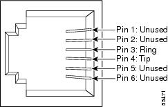
Figure 3 RJ-11 Connector Pinout
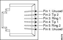
Figure 4 RJ-14 Connector Pinout
Connections That Use RJ-11 Connectors
The following figures illustrate common configurations:
•Figure 5 shows the connections between a phone system and the primary and secondary master PIMG units, through a punchdown cross-connect block.
•Figure 6 shows the connections between a phone system with an RJ-11 connector and the primary and secondary master PIMG units.
•Figure 7 shows the connections between a phone system with an RJ-14 connector and the primary and secondary master PIMG units.
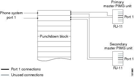
Figure 5 Connections from the Phone System Through a Punchdown Block
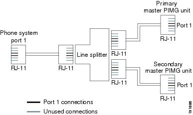
Figure 6 Connections for an RJ-11 Connector from the Phone System
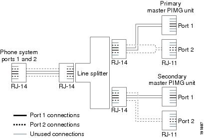
Figure 7 Connections for an RJ-14 Connector from the Phone System
Serial Data Cable Connections for the Master PIMG Units
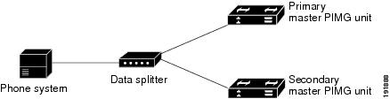
Connecting the RS-232 serial cables between a circuit-switched phone system and the primary and secondary master PIMG varies depending on the number of serial ports the phone system has.
Requirements
The following components are required for phone systems with only one serial port:
•Three RS-232 serial cables
•Data splitter unit
The following components are required for phone systems with multiple serial ports:
•Two RS-232 serial cables
Connections for the Serial Data Cables
Figure 8 shows the connections between the serial port on a phone system that has only one serial port to the serial ports on the primary and secondary master PIMG units. Figure 9 shows the connections between the serial ports on a phone system that has two serial ports to the serial ports on the master PIMG units.
Note that the following figures do not show the analog voice lines, which are described in the "Analog Voice Line Connections for the Master PIMG Units" section.
Figure 8 Serial Cable Connections from a Single Serial Port on the Phone System to the Serial Ports on the Master PIMG Units
Figure 9 Serial Cable Connections from Multiple Serial Ports on the Phone System to the Serial Ports on the Master PIMG Units
Configuring the Secondary Master PIMG Unit
This procedure has the following requirements:
•All analog lines and serial cables must be correctly connected.
•The primary secondary master PIMG units must have the same firmware version installed.
•The primary master PIMG unit is connected to power, while the secondary master PIMG unit is disconnected from power.
•You have a Windows workstation that has access to the PIMG units.
Do the following procedure to make the configuration of the secondary master PIMG unit match the configuration of the primary master PIMG unit.
To Configure the Secondary Master PIMG Unit
Step 1 On a Windows workstation, in a web browser, log on to the primary master PIMG unit.
Step 2 On the Configure menu, click Import/Export.
Step 3 On the Import/Export page, under Export Settings, click Export Settings.
Step 4 In the File Download dialog box, click Save.
Step 5 In the Save As dialog box, browse to the Windows workstation, browse to a directory where you want to save the file, and click Save.
Step 6 Exit the PIMG web interface.
Step 7 Disconnect power from the primary master PIMG unit.
Step 8 Connect power to the secondary master PIMG unit.
Step 9 On the Windows workstation, in a web browser, log on the secondary master PIMG unit.
The following are the default case-sensitive settings for the System Login page.
Step 10 Click Log On.
Step 11 On the Configure menu of the secondary master PIMG unit, click Import/Export.
Step 12 On the Import/Export page, under Import Settings, click Browse.
Step 13 In the Choose File dialog box, browse to the file Config.ini that you saved from the primary master PIMG unit in Step 5.
Step 14 Click Config.ini, and click Open.
Step 15 On the Import/Export page, click Import Settings.
Step 16 When prompted to restart the PIMG unit, click OK.
Step 17 Disconnect power from the secondary master PIMG unit.
Step 18 Connect power to the primary master PIMG unit.
Appendix: Using Alternate Extensions and MWIs
Alternate Extensions
In addition to the "primary" extension that you specify for subscribers, you can assign subscribers up to nine alternate extensions. (The primary extension is the one that you assign to each subscriber when you create his or her subscriber account; it is listed on the Subscribers > Subscribers > Profile page.)
Reasons to Use Alternate Extensions
There are several reasons that you may want to specify alternate extensions for subscribers. For example, if you have more than one Cisco Unity server that accesses a single, corporate-wide directory, you may want to use alternate extensions to simplify addressing messages to subscribers at the different locations. With alternate extensions, the number that a subscriber uses when addressing a message to someone at another location can be the same number that the subscriber dials when calling. You may also want to use alternate extensions to:
•Handle multiple line appearances on subscriber phones.
•Offer easy message access on direct calls from a cell phone, home phone, or phone at an alternate work site (assuming that the phone number is passed along to Cisco Unity from these other phone systems). In addition, when such phones are used as alternate extensions, and are set to forward to Cisco Unity, callers can listen to the subscriber greeting, and leave messages for the subscriber just as they would when dialing the primary extension for the subscriber.
Tip To reduce the number of requests from subscribers who want alternate extensions set up for multiple cell phones, home phones, and other phones, give subscribers class of service (COS) rights to specify their own set of alternate extensions. (See the Subscribers > Class of Service > Profile page.) With proper COS rights, a subscriber can specify up to five alternate extensions in the Cisco Unity Assistant—in addition to the nine that you can specify on the Subscribers > Alternate Extensions page in the Cisco Unity Administrator.
•Enable URL-based extensions in Cisco Unity for an integration with a SIP phone system.
How Alternate Extensions Work
Before you set up alternate extensions, review the following list for information on how alternate extensions work:
•Alternate extensions cannot exceed 30 characters in length. By default, each administrator-defined alternate extension must be at least 3 characters in length, while subscriber-defined alternate extensions must be at least 10 characters.
You can use the Advanced Settings tool in Tools Depot to specify a minimum extension length for the extensions entered in the Cisco Unity Administrator and the Cisco Unity Assistant. Refer to the Advanced Settings Tool Help for details on using the settings. Respectively, the settings are Administration—Set the Minimum Length for Locations, and Administration—Set the Minimum Length for Subscriber-Defined Alternate Extensions.
•You can control whether subscribers can use the Cisco Unity Assistant to view the alternate extensions that you specify in the Cisco Unity Administrator. To do so, see the Subscribers > Class of Service > Profile page. The Subscriber-Defined Alternate Extension table displays the alternate extensions that the subscriber adds.
•Neither the Cisco Unity Administrator nor the Cisco Unity Assistant will accept an extension that is already assigned to another subscriber (either as a primary or alternate extension), or to a public distribution list, call handler, directory handler, or interview handler. Cisco Unity verifies that each alternate extension is unique—up to the dialing domain level, if applicable—before allowing either an administrator or a subscriber to create it.
•All alternate extensions use the same transfer settings as the primary extension.
•In many cases, Cisco Unity can activate a message waiting indicator (MWI) for an alternate extension. However, depending on the phones and phone systems involved, some additional phone system programming may be required to set this up.
Setting Up Alternate Extensions
Do the applicable procedure to add, modify, or delete alternate extensions:
•To Add Administrator-Defined Alternate Extensions
•To Modify or Delete Alternate Extension(s)
To Add Administrator-Defined Alternate Extensions
Step 1 In the Cisco Unity Administrator, go to any Subscribers > Alternate Extensions page.
Step 2 In the Administrator-Defined Alternate Extensions table, enter an extension in any row. When entering characters in the Alternate Extensions table, consider the following:
•You can enter an extension up to 30 characters in length. (SIP integrations can use up to 30 alphanumeric characters.)
•Each extension must be unique—up to the dialing domain level, if applicable.
•Enter digits 0 through 9. Do not use spaces, dashes, or parentheses.
•For SIP integrations, you can also enter a valid alias for a SIP URL. For example, if the URL is SIP:aabade@cisco.com, enter aabade. Do not use spaces.
•Rows are numbered as a convenience. You can enter alternate extensions in any order, and you can have blank rows.
Step 3 Repeat Step 2 as necessary.
Step 4 Click the Save icon. Alternate extensions are enabled for all rows in the table.
To Modify or Delete Alternate Extension(s)
Step 1 In the Cisco Unity Administrator, go to any Subscribers > Alternate Extensions page.
Step 2 Do any of the following:
•To modify an extension, change the extension in the Alternate Extensions table.
•To delete extensions, check the check boxes next to the alternate extensions that you want to delete.
•To remove all alternate extensions listed in the table, click Select All.
Step 3 Click the Save icon.
Step 4 Repeat Step 2 and Step 3 as necessary.
Note You can run the Cisco Unity Bulk Import wizard when you want to add alternate extensions for multiple subscribers at once. When you do, the Cisco Unity Bulk Import wizard appends the new alternate extensions to the existing table of alternate extensions, beginning with the first blank row.
Alternate MWIs
You can set up Cisco Unity to activate alternate MWIs when you want a new message for a subscriber to activate the MWIs at up to 10 extensions. For example, a message left at extension 1001 can activate the MWIs on extensions 1001 and 1002.
Cisco Unity uses MWIs to alert the subscriber to new voice messages. MWIs are not used to indicate new e-mail, fax, or return receipt messages.
Setting Up Alternate MWIs
Cisco Unity can activate alternate MWIs. Note that depending on the phones and phone systems, some additional phone system programming may be necessary. Refer to the installation guide for the phone system.
To enable alternate MWIs for extensions, do the following procedure for each subscriber who needs alternate MWIs.
To Set Up Alternate MWIs for Extensions
Step 1 In the Cisco Unity Administrator, go to the applicable Subscribers > Subscribers > Messages page.
Step 2 Confirm that the Use MWI for Message Notification check box is checked.
Step 3 Click the Add button located beneath the MWI Extensions table to add a row to the table. By default, the first row in the table contains an "X" to indicate the primary extension assigned to a subscriber. If you want one more extension and do not need to activate the MWI on the primary extension, you can also modify the first row.
Step 4 Enter the applicable extension in the Extension field of the table. MWIs are automatically enabled for all rows in the table. When entering characters in the MWI Extensions table, consider the following:
•Enter digits 0 through 9. Do not use spaces, dashes, or parentheses.
•Enter , (comma) to insert a one-second pause.
•Enter # and * to correspond to the # and * keys on the phone.
Step 5 Click the Save icon.
Step 6 Repeat Step 3 through Step 5 as necessary.
Note You can run the Cisco Unity Bulk Import wizard when you want to set up alternate MWIs for multiple subscribers at once.
To change or delete alternate MWIs for extensions, do the following procedure.
To Modify or Delete Alternate MWIs
Step 1 In the Cisco Unity Administrator, go to the applicable Subscribers > Subscribers > Messages page.
Step 2 Do either of the following:
•To modify an extension, change the extension in the MWI Extensions table.
•To delete extensions, check the check boxes next to the rows that you want to delete in the MWI Extensions table, and then click the Delete button.
Step 3 Click the Save icon.
Step 4 Repeat Step 2 and Step 3 as necessary.
Appendix: PIMG Integrations Over a WAN That Use the G.729a Codec May Need to Disable Comfort Noise
Note This appendix applies only to systems that use PIMG units with PIMG firmware release 4, SU6 or earlier.
When the PIMG units connect to a WAN, use the G.729a codec, and have firmware release 4 SU6 or earlier, you must disable comfort noise. Otherwise, callers will hear loud comfort noise after pressing a DTMF key or between prompts when recording a message.
To Disable Comfort Noise
Step 1 On the Cisco Unity server, on the Start menu, click Run.
Step 2 In the Run dialog box, enter regedit and click OK.
Caution Changing the wrong registry key or entering an incorrect value can cause the server to malfunction. Before you edit the registry, confirm that you know how to restore it if a problem occurs. (Refer to the "Restoring" topics in Registry Editor Help.) Note that for a Cisco Unity failover system, registry changes on one Cisco Unity server must be made manually on the other Cisco Unity server, because registry changes are not replicated. If you have any questions about changing registry key settings, contact Cisco TAC.
Step 3 If you do not have a current backup of the registry, save the registry settings to a file by doing the following depending on the Windows version:
Step 4 Expand the registry key
HKEY_LOCAL_MACHINE\System\CurrentControlSet\Services\Avaudio\Parameters
and double-click the ComfortNoise value in the right pane.Step 5 In the Edit DWORD Value dialog box, under Base, click Decimal.
Step 6 In the Value Date field, enter 128.
Step 7 Click OK.
Step 8 Exit the Registry Editor.
Step 9 Restart the Cisco Unity server.
Step 10 If you are using failover, repeat this procedure to apply the registry setting to the secondary Cisco Unity server.
Appendix: Documentation and Technical Assistance
Conventions
The Nortel SL-100 Serial PIMG Integration Guide for Cisco Unity 4.0 uses the following conventions.
The Nortel SL-100 Serial PIMG Integration Guide for Cisco Unity 4.0 also uses the following conventions:
Note Means reader take note. Notes contain helpful suggestions or references to material not covered in the document.
Caution Means reader be careful. In this situation, you might do something that could result in equipment damage or loss of data.
For descriptions and URLs of Cisco Unity documentation on Cisco.com, see the Cisco Unity Documentation Guide. The document is shipped with Cisco Unity and is available at http://www.cisco.com/univercd/cc/td/doc/product/voice/c_unity/about/aboutdoc.htm.
Obtaining Documentation, Obtaining Support, and Security Guidelines
For information on obtaining documentation, obtaining support, providing documentation feedback, security guidelines, and also recommended aliases and general Cisco documents, see the monthly What's New in Cisco Product Documentation, which also lists all new and revised Cisco technical documentation, at:
http://www.cisco.com/en/US/docs/general/whatsnew/whatsnew.html
Any Internet Protocol (IP) addresses used in this document are not intended to be actual addresses. Any examples, command display output, and figures included in the document are shown for illustrative purposes only. Any use of actual IP addresses in illustrative content is unintentional and coincidental.
© 2007 Cisco Systems, Inc. All rights reserved.