-
Cisco Unity Installation Guide, Release 3.0(2)
-
Preface
-
Chapter 1 - Cisco Unity Configuration Overview
-
Chapter 2 - Installing a Cisco Unity System
-
Chapter 3 - Upgrading the Cisco Unity System from Version 2.x to 3.0
-
Chapter 4 - Upgrading a Cisco Unity 3.0 System
-
Appendix A - Voice Cards
-
Appendix B - Exiting and Starting the Cisco Unity Software and Server
-
Appendix C - Downgrades
-
Appendix D - Regulatory Compliance and Safety Information
-
 Feedback
Table Of Contents
Dialogic D/120JCT-LS and D/120JCT-EURO
Voice Cards
This appendix contains the following sections:
•
Dialogic D/120JCT-LS and D/120JCT-EURO
Dialogic D/41E PCI
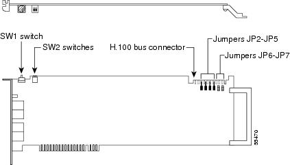
Figure A-1 D/41E PCI Top and Side Views
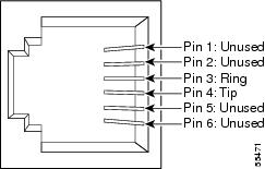
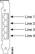
Figure A-2 D/41E PCI Connection Pinouts and Backplate
The D/41E PCI uses RJ-11 connectors.
If you are installing cards that have H.100 connectors, you need an H.100 cable that has at least as many connectors as you have cards (you must connect all cards by using a single cable) but no more than five extra connectors.
Hardware Settings
To set switches and jumpers
Step 1
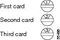
Each Dialogic card with a rotary switch in the Cisco Unity server—regardless of model number—must have a unique value, starting with 1 and continuing in sequence on subsequent cards. For example, set the rotary switch on the first three voice cards as shown below. This is also the order in which you install the cards in the server.
Step 2
Step 3
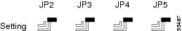
Set jumpers JP2 through JP5 to Off (Figure A-3) on
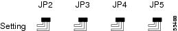
the card.Set jumpers JP2 through JP5 to On (Figure A-4) on
both cards.Set jumpers JP2 through JP5 to On (Figure A-4) on the first and last cards.
Set jumpers JP2 through JP5 to Off (Figure A-3) on all other cards.
Figure A-3 D/41E PCI Jumpers JP2 Through JP 5: Off
Figure A-4 D/41E PCI Jumpers JP2 Through JP 5: On
Step 4
Dialogic D/120JCT-LS and D/120JCT-EURO
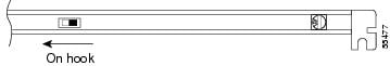
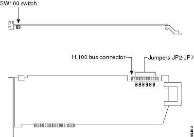
Figure A-5 D/120JCT-LS and D/120JCT-EURO Top and Side Views
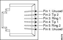
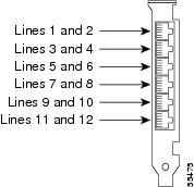
Figure A-6 D/120JCT-LS and D/120JCT-EURO Connection Pinouts and Backplate
The D/120JCT-LS and D/120JCT-EURO use RJ-14 connectors.
If you are installing cards that have H.100 connectors, you need an H.100 cable that has at least as many connectors as you have cards (you must connect all cards by using a single cable) but no more than five extra connectors.
Hardware Settings
To set switches
Step 1
Each Dialogic card with a rotary switch in the Cisco Unity server—regardless of model number—must have a unique value, starting with 1 and continuing in sequence on subsequent cards. For example, set the rotary switch on the first three voice cards as shown below. This is also the order in which you install the cards in the server.
Step 2
Software Settings
Do the following procedure only if the Cisco Unity server contains D/120JCT-EURO voice cards.
To select the country for D/120JCT-EURO voice cards
Step 1
Step 2
Step 3
Step 4
Step 5
Step 6
Step 7
Step 8
Step 9
Step 10
Step 11
Step 12
Step 13
Step 14
Step 15
Step 16
Dialogic D/240PCI-T1
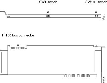
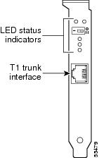
Figure A-7 D/240PCI-T1 Top and Side Views
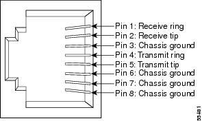
Figure A-8 D/240PCI-T1 Connection Pinouts and Backplate
The D/240PCI-T1 uses an RJ-48C connector.
If you are installing cards that have H.100 connectors, you need an H.100 cable that has at least as many connectors as you have cards (you must connect all cards by using a single cable) but no more than five extra connectors.
Hardware Settings
To set switches and jumpers
Step 1
Each Dialogic card with a rotary switch in the Cisco Unity server—regardless of model number—must have a unique value, starting with 1 and continuing in sequence on subsequent cards. For example, set the rotary switch on the first three voice cards as shown below. This is also the order in which you install the cards in the server.
Step 2
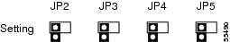
Set jumpers JP2 through JP5 to Off (Figure A-9) on
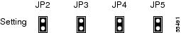
the card.Set jumpers JP2 through JP5 to On (Figure A-10) on
both cards.Set jumpers JP2 through JP5 to On (Figure A-10) on the first and last cards.
Set jumpers JP2 through JP5 to Off (Figure A-9) on all other cards.
Figure A-9 D/240PCI-T1 Jumpers JP2 Through JP 5: Off
Figure A-10 D/240PCI-T1 Jumpers JP2 Through JP 5: On
Step 3
Software Settings
For a D/240PCI-T1 voice card, you must set the protocol manually after Cisco Unity Setup is finished.
To set the protocol
Step 1
Step 2
Step 3
Step 4
Step 5
Step 6
Step 7
Step 8
Step 9
Step 10
Step 11
Step 12
Step 13
Step 14