Feedback
Contents
- Cisco Unified IP Color Key Expansion Module Setup
- Key Expansion Module Installation on Cisco Unified IP Phone
- KEM Power Information
- Connect Single KEM to Cisco Unified IP Phone
- Connect Two or More KEMs to Phone Using KEM Spine Connector
- Additional KEM Connection Methods
- Set up Key Expansion Module in Cisco Unified Communications Manager Administration
- Key Expansion Module Settings on Phone
- Access the Key Expansion Module Setup
- Upgrade the Key Expansion Module
- Key Expansion Module Removal
- Troubleshoot the KEM
Cisco Unified IP Color Key Expansion Module Setup
The Cisco Unified IP Color Key Expansion Module (KEM) attaches to your Cisco Unified IP Phone 8961, 9951, and 9971 to add additional line appearances, speed dials, or programmable buttons to your phone. The programmable buttons can be set up as phone line buttons, speed-dial buttons, or phone feature buttons.
Most call functions, such as answering a call, placing a call on hold, and transferring a call, can be performed with the Cisco Unified IP Color Key Expansion Module.
The following table lists the Cisco Unified IP Phones and the number of Key Expansion Modules that each model supports.
NoteFor information about installing a wall mount kit for a phone that includes a Cisco Unified IP Color Key Expansion Module, see Wall Mount Components for Phone with Key Expansion Module.
- Key Expansion Module Installation on Cisco Unified IP Phone
- Set up Key Expansion Module in Cisco Unified Communications Manager Administration
- Key Expansion Module Settings on Phone
- Upgrade the Key Expansion Module
- Key Expansion Module Removal
- Troubleshoot the KEM
Key Expansion Module Installation on Cisco Unified IP Phone
This section describes the requirements and steps to install a Cisco Unified IP Phone Key Expansion Module.
- KEM Power Information
- Connect Single KEM to Cisco Unified IP Phone
- Connect Two or More KEMs to Phone Using KEM Spine Connector
- Additional KEM Connection Methods
KEM Power Information
The Cisco Unified IP Color Key Expansion Module for the Cisco Unified IP Phone 8961, 9951, and 9971 possesses the following power consumption and power scheme:
- Power consumption
48V DC, 5W per KEM
- Power scheme
- If the Cisco Unified IP Phone 8961, 9951, and 9971 uses AT PoE, at least one KEM can be powered up.
- If the phone uses a power adapter, three KEMs can be powered up for the Cisco Unified IP Phone 9971, two KEMs can be powered up for the Cisco Unified IP Phone 9951, and one KEM can be powered up for the Cisco Unified IP Phone 8961.
- If the Cisco Unified IP Phone 8961, 9951, and 9971 uses AF PoE, a KEM cannot be powered up.
- With AT power, the Cisco Unified IP Phones 9951 and 9971 can support two KEMs plus a USB headset or another USB device that is independently powered and only uses USB for signalling.
- The Cisco Unified IP Phone 9971 needs a power cube to support three KEMS.
- With AF power, the Cisco Unified IP Phones 9951 and 9971 need power cubes for any KEMS. The Cisco Unified IP Phone 8961 can support one KEM with CDP, AF power, and no power cube.
Connect Single KEM to Cisco Unified IP Phone
Procedure
Connect Two or More KEMs to Phone Using KEM Spine Connector
ProcedureTo connect two or more KEMs to the Cisco Unified IP Phone, follow these steps:
Note
Cisco offers two other methods of connecting KEMs to your phone, if a shortage of desk space prevents you from using the spine connectors that are described in the following procedure, or if you need access to the speaker and microphone ports (on the Cisco Unified IP Phones 9951 and 9971) that the KEM spine connector covers up. For more information, see Additional KEM Connection Methods.
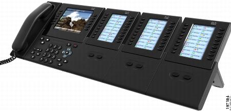
Step 1 Position the phone so that the front of the phone is facing up. Step 2 Connect one end of the KEM spine connector to the accessory connector on the Cisco Unified IP Phone and the other end of the spine connector to a KEM, as seen in Connect Single KEM to Cisco Unified IP Phone. The first KEM is now connected to the Cisco Unified IP Phone. Step 3 Use a second KEM spine connector to connect the second KEM to the first KEM. Step 4 Use a third KEM spine connector to connect the third KEM to the second (middle) KEM. The following figure shows a Cisco Unified IP Phone with three KEMs attached. Step 5 Fasten the screws on the spine connectors after connecting both the ends.
Additional KEM Connection Methods
Cisco provides the following additional methods of connecting KEMs to your phone; choose the one that best fits your needs:
- Tethered spine connector cable: You can insert the connector plugs on the tethered spine connector cable into the spine receptacles on the phone and KEM; this method lets you fit the phone and KEMs into your allotted space so that they do not need to be side by side. You can also arrange them so that the audio ports on your phone (Cisco Unified IP Phone 9951 and 9971) remain accessible for an external speaker and microphone.
- Dongle: You can use the dongle if you prefer to use the KEM spine connector method but still want the phone audio ports (on the Cisco Unified IP Phone 9951 or 9971) to remain accessible for an external speaker and microphone.
Note
Plugging in the dongle disables the speakerphone. Therefore, the dongle must be plugged into a speaker and microphone to use the speakerphone feature.
Set up Key Expansion Module in Cisco Unified Communications Manager Administration
ProcedureTo configure the Cisco Unified IP Color Key Expansion Module on the Cisco Unified IP Phone, follow these steps:
Step 1 In Cisco Unified Communications Manager Administration, choose . The Find and List Phones window appears. You can search for one or more phones that you want to configure for the Cisco Unified IP Color Key Expansion Module.
Step 2 Select and enter your search criteria and click Find. The Find and List Phones window appears with a list of phones that match your search criteria.
Step 3 Click the IP phone that you want to configure for the Cisco Unified IP Color Key Expansion Module. The Phone Configuration window appears. Step 4 Scroll down to the Expansion Module Information section on the right pane of the Phone Configuration window, and choose the appropriate expansion module (or "none") for the Module 1, Module 2 and Module 3 fields, in that order. For the Module Load Name, enter the custom software for the appropriate expansion module, if applicable. The value that you enter overrides the default value for the current model. Ensure that the firmware load matches the module load. If the Module Load Name is left blank, the default load (the load bundled with the phone load) is installed.
For the number of supported KEMs per phone model, see Cisco Unified IP Color Key Expansion Module Setup.
Step 5 Ensure that the Side USB Port parameter is enabled.
Note If the Side USB Port is disabled, the KEM does not work.
Step 6 Be sure to select the phone button template (in the Device Information portion of the Phone Configuration window) that is configured to make full use of the KEMs attached to the phone. Step 7 Click Save.
Key Expansion Module Settings on Phone
After you install one or more KEMs on the phone and configure them in Cisco Unified Communications Manager Administration, the KEMs are automatically recognized by the Cisco Unified IP Phone 8961, 9951, and 9971.
When multiple KEMs are attached, they are numbered according to the order in which they connect to the phone. For example (see Connect Two or More KEMs to Phone Using KEM Spine Connector):
- Key Expansion Module 1 is the KEM closest to the phone.
- Key Expansion Module 2 is the KEM in the middle.
- Key Expansion Module 3 is the KEM farthest to the right.
You can select a KEM, and then choose one of the following softkeys:
- Exit: Returns to the Applications menu.
- Details: Provides details about the selected KEM.
- Setup: Allows you to configure the brightness of the selected KEM. This can also be done using the Preferences menu. For details, see the Cisco Unified IP Phone 8961, 9951, and 9971 User Guide for Cisco Unified Communications Manager (SIP), "Accessories" chapter, "Adjust brightness" section.
Upgrade the Key Expansion Module
Procedure
Step 1 Power on the KEM, press Page 1, and do not release the key. When the LCD turns white, continue pressing Page 1 for at least one second. Step 2 Release Page 1; LEDs should turn red. Immediately press Page 2 and continue pressing Page 2 for at least one second. Step 3 Release Page 2; all LEDs should turn amber. Step 4 Press Lines 5, 14, 1, 18, 10, and 9 in sequence. The LCD should turn blue, and the spinning loader icon displays in the center.
The KEM starts to upgrade.
Key Expansion Module Removal
If you need to remove all existing KEMs from the phone, detach them from the phone, then go to Cisco Unified Communications Manager Administration and update the phone configuration file accordingly.
If you are removing one or more KEMs but still leaving one or more KEMs attached to the phone, see Key Expansion Module Installation on Cisco Unified IP Phone for instructions on how to connect the KEMs and phone based on how many KEMs remain. Also, go to Cisco Unified Communications Manager Administration and update the phone configuration file accordingly.