Feedback
Table Of Contents
Setting Up the Cisco Unified Wireless IP Phone 7925G, 7925G-EX, and 7926G
Methods for Adding Phones to Cisco Unified Communications Manager
Adding Phones with Auto-Registration
Adding Phones with Auto-Registration and TAPS
Adding Phones with Cisco Unified Communications Manager Administration
Installing the Cisco Unified Wireless IP Phone 7925G, 7925G-EX, and 7926G
Installing or Removing the Phone Battery
Using the Power Supply to Charge the Phone Battery
Using the USB Cable and PC to Charge the Battery
Configuring Wireless LAN Settings for the Cisco Unified Wireless IP Phone 7925G, 7925G-EX, and 7926G
Cisco Unified Wireless IP Phone 7925G, 7925G-EX, and 7926G Web Pages
Network Profile Menu on the Cisco Unified Wireless IP Phone 7925G, 7925G-EX, and 7926G
Using Bluetooth Wireless Headsets
Audio Quality Subjective to the User
Using External Devices with Cisco Unified IP Phones
Powering On the Cisco Unified Wireless IP Phone 7925G, 7925G-EX, and 7926G
Active and Standby Phone Modes
Understanding the Phone Startup Process
Setting Up the Cisco Unified Wireless IP Phone 7925G, 7925G-EX, and 7926G
This chapter includes the following topics, which help you install and configure the Cisco Unified Wireless IP Phone 7925G, 7925G-EX, and 7926G on an IP telephony network:
•
Installing the Cisco Unified Wireless IP Phone 7925G, 7925G-EX, and 7926G
•
•
Before You Begin
Before installing a Cisco Unified Wireless IP Phone 7925G, 7925G-EX, and 7926G, review the requirements in these sections:
•
Network Requirements
For the Cisco Unified Wireless IP Phone 7925G, 7925G-EX, and 7926G to successfully operate as a Cisco Unified IP Phone endpoint, your network must support these requirements:
Voice over Wireless LAN
•
•
•
Note
VoIP Network
•
•
–
–
•
Related Topics
•
•
•
•
•
Methods for Adding Phones to Cisco Unified Communications Manager
Before installing the wireless IP phone, you must choose a method for adding phones to the Cisco Unified Communications Manager database. Some methods require entering the MAC address of the phone. Table 3-1 provides an overview of these methods.
The following sections describe methods for adding phones:
•
•
•
Adding Phones with Auto-Registration
Use auto-registration to enter phones into the Cisco Unified Communications Manager database without first gathering MAC addresses from the phones. When auto-registration is enabled, Cisco Unified Communications Manager automatically assigns the next available sequential directory number (DN) to new phones during the initial phone startup process.
After registering the phones, you can modify settings, such as the DNs and device pools, by using Cisco Unified Communications Manager Administration.
Note
Related Topics
•
•
Adding Phones with Auto-Registration and TAPS
Use auto-registration and TAPS to add phones to the Cisco Unified Communications Manager database. Add the phones first by using BAT to the Cisco Unified Communications Manager database with dummy MAC addresses. Then use TAPS to update MAC addresses and download predefined configurations for the phones.
To implement TAPS, dial a TAPS DN and follow voice prompts. When the process is complete, the phone has downloaded its DN and other settings. The correct MAC address for the phone is updated in Cisco Unified Communications Manager Administration.
Note
For Cisco Unified Communications Manager Release 5.0 or earlier, see Bulk Administration Tool User Guide for Cisco Unified Communications Manager for detailed instructions about BAT and TAPS. For Cisco Unified Communications Manager Release 6.0 or later, see Cisco Unified Communications Manager Bulk Administration Guide.
Related Topics
•
•
Adding Phones with BAT
Add a group of phones to the Cisco Unified Communications Manager database by using BAT. This tool performs batch operations, including registration, on multiple phones. You need the MAC addresses for each phone before you use BAT.
Table 3-2 describes how to determine the MAC address of the wireless IP phone.
Note
For detailed instructions about using BAT, see the following documents:
•
•
Note
Related Topics
•
•
•
Adding Phones with Cisco Unified Communications Manager Administration
Add phones individually by using Cisco Unified Communications Manager Administration. To do so, obtain the MAC address for each phone before you begin. See "Methods for Adding Phones to Cisco Unified Communications Manager" section for instructions.
Perform one of the following after collecting the MAC addresses:
•
•
For additional instructions and conceptual information about Cisco Unified Communications Manager, see Cisco Unified Communications Manager Administration Guide and Cisco Unified Communications Manager System Guide.
Related Topics
•
•
Device Support
Cisco Unified Communications Manager Release 4.3 or later require a device package or service release update installed to enable device support for the Cisco Unified Wireless IP Phone 7925G, 7925G-EX, and 7926G. Device packages including support for the Cisco Unified Wireless IP Phone 7925G, 7925G-EX, and 7926G are available at http://www.cisco.com/kobayashi/sw-center/sw-voice.shtml.
Safety Information
Review the following warnings before installing the Cisco Unified Wireless IP Phone. To see translations of these warnings, see the Regulatory Compliance and Safety Information for the Cisco Unified Wireless IP Phone 7920 Series and Peripherals document that accompanied this device.
Warning
Warning
Warning
Warning
Warning
Warning
Warning
Warning
Warning
Warning
Warning
Battery Safety Notices
The following battery safety notices apply to the batteries that are approved by the Cisco Unified Wireless IP Phone 7925G, 7925G-EX, and 7926G manufacturer.
Warning
Warning
Caution
Caution
Caution
Caution
Caution
Caution
Caution
To obtain a replacement battery, contact your local dealer. Use only the batteries that have the following Cisco part numbers.
Standard battery—CP-BATT-7925G-STD
Extended battery—CP-BATT-7925G-EXT
Caution
Australia—CP-PWR-7925G-AU
Central Europe—CP-PWR-7925G-CE
China—CP-PWR-7925G-CN
Japan—CP-PWR-7925G-JP
North America—CP-PWR-7925G-NA
United Kingdom—CP-PWR-7925G-UK
Related Topics
Installing the Cisco Unified Wireless IP Phone 7925G, 7925G-EX, and 7926G
After setting up the wireless network to support voice communications and configuring the wireless IP phones in Cisco Unified Communications Manager, you are ready to install the phones. This section includes the following installation information:
•
Providing Power to the Phone
The Cisco Unified Wireless IP Phone 7925G, 7925G-EX, and 7926G uses a battery for power. Table 3-3 lists the types of batteries available for the wireless IP phone and the maximum talk and standby times.
Use U-APSD for talk-time power save mode. Also 5 GHz talk time is reduced up to 30 minutes for a standard battery and up to 2 hours for an extended battery. Use of 802.11b/g and a Bluetooth headset can reduce the talk time by 40 to 50 percent. To extend talk-time battery life, the Cisco Unified Wireless IP Phone 7925G, 7925G-EX, and 7926G can use PS-POLL power save methods. The Cisco Unified Wireless IP Phone 7925G, 7925G-EX, and 7926G uses either U-APSD or PS-POLL when in idle (no active phone call).
When an AP supports the Cisco Client Extensions (CCX) proxy ARP information element, the idle battery life is optimized. If the AP does not support CCX or proxy ARP is not enabled, then the idle battery life is up to 50 percent less.
Table 3-4 shows the charging time for the two types of batteries. You can stop charging the battery when the battery is fully charged. Lithium ion batteries can be partially charged without shortening the battery life. Batteries should handle up to 4,000 recharges.
Note
Table 3-4 Battery Charging Time Information
and USB CableStandard
2 hours
5 hours
Extended
3 hours
7 hours
The following sections provide information about the battery and charging the phone:
•
•
•
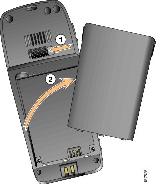
Installing or Removing the Phone Battery
To install the battery in the Cisco Unified Wireless IP Phone 7925G, 7925G-EX, and 7926G use Figure 3-1, and follow these steps:
Procedure
Step 1
Step 2
Step 3
Step 4
Figure 3-1 Removal of Cover to Install the Battery
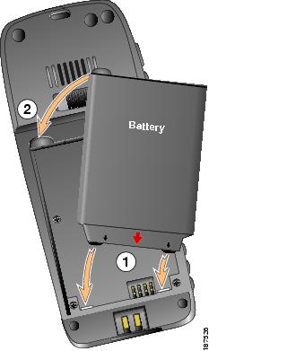
Figure 3-2 Install the Battery
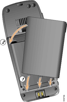
Figure 3-3 Replace the Back Cover
Note
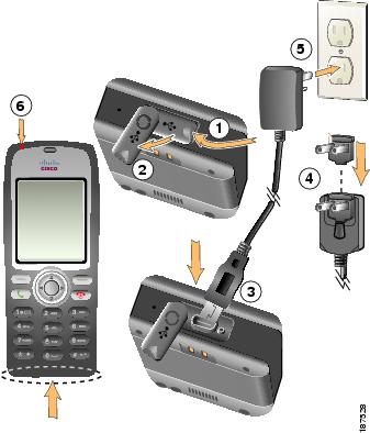
Using the Power Supply to Charge the Phone Battery
To charge the phone battery quickly, follow the steps in Figure 3-4.
Figure 3-4 Charging the Phone Battery
Note
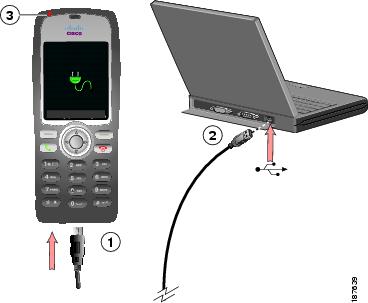
Using the USB Cable and PC to Charge the Battery
Charge the phone battery by using a USB cable connected to your PC. Follow the steps in Figure 3-5.
Figure 3-5 Charging the Phone Battery Using the USB Cable and PC
Note
Related Topics
•
•
•
Configuring Wireless LAN Settings for the Cisco Unified Wireless IP Phone 7925G, 7925G-EX, and 7926G
Before the phone can connect to the WLAN, you must configure the network profile for the phone with the WLAN settings. You can use two methods for setting up the network profiles:
•
•
Cisco Unified Wireless IP Phone 7925G, 7925G-EX, and 7926G Web Pages
You can access the Cisco Unified Wireless IP Phone 7925G, 7925G-EX, and 7926G web pages to set up the WLAN settings in the network profile. For a new phone with the factory default settings, you must use the USB cable to connect the phone to your PC. For more information and instructions, see Chapter 4, "Using the Cisco Unified Wireless IP Phone 7925G, 7925G-EX, and 7926G Web Pages."
Network Profile Menu on the Cisco Unified Wireless IP Phone 7925G, 7925G-EX, and 7926G
You can use the Settings menu on the phone and access the Network Profiles menu to set up the network configuration and the WLAN configuration. For more information and instructions, see Chapter 5, "Configuring Settings on the Cisco Unified Wireless IP Phone 7925G, 7925G-EX, and 7926G."
Using a Headset
Although Cisco performs some internal testing of third-party wired and Bluetooth wireless headsets for use with the Cisco Unified Wireless IP Phone 7925G, 7925G-EX, and 7926G, Cisco does not certify or support products from headset or handset vendors. Because of the inherent environmental and hardware inconsistencies in the locations where Cisco Unified IP Phones are deployed, there is not a single "best" solution that is optimal for all environments. Cisco recommends that customers test the headsets that work best in their environment before deploying a large number of units in their network.
Warning
Cisco recommends the use of good quality external devices, like headsets that are screened against unwanted radio frequency (RF) and audio frequency (AF) signals. Depending on the quality of these devices and their proximity to other devices such as cell phones and two-way radios, some audio noise may still occur. See Using External Devices with Cisco Unified IP Phones for more information.
The primary reason that a particular headset would be inappropriate for the Cisco Unified IP Phone is the potential for an audible hum. This hum can be heard by either the remote party or by both the remote party and the Cisco Unified IP Phone user. Some potential humming or buzzing sounds can be caused by a range of outside sources; for example, electric lights, being near electric motors or large PC monitors. In some instances, the mechanics or electronics of various headsets can cause remote parties to hear an echo of their own voice when they speak to Cisco Unified IP Phone users.
Connecting Headsets
To connect a headset to the Cisco Unified Wireless IP Phone 7925G, 7925G-EX, and 7926G, plug it into the headset port on the right side of the phone.
You can use the headset with all of the features on the Cisco Unified Wireless IP Phone 7925G, 7925G-EX, and 7926G, including the Volume and Mute buttons. Use these buttons to adjust the ear piece volume and to mute the speech path from the headset microphone.
Using Bluetooth Wireless Headsets
The Cisco Unified Wireless IP Phone 7925G, 7925G-EX, and 7926G supports Bluetooth Class 2 technology with Hands Free version 1.5 when the headsets support Bluetooth. Bluetooth enables low bandwidth wireless connections within a range of 10 meters. The best performance is in the 1 to 2 meter range.
There can be a potential interference issues. It is recommended that you:
•
•
Using Bluetooth wireless headsets will likely increase battery power consumption on your phone and might result in reducing battery life.
For a Bluetooth wireless headset to work, it does not need to be within direct line-of-sight of the phone, but some barriers, such as walls or doors, and interference from other electronic devices, could affect the connection.
Pairing Headsets
The Cisco Unified Wireless IP Phone 7925G, 7925G-EX, and 7926G pairs with headsets using a shared key authentication and encryption method. The authentication process can require a personal identification number (PIN) specific to the headset, commonly "0000." The Cisco Unified Wireless IP Phone 7925G, 7925G-EX, and 7926G can be paired with more than one headset at a time. Pairing is typically performed once for each headset.
After a device has been paired, its Bluetooth connection remains as long as both devices (phone and headset) are enabled and within range of each other. The connection re-establishes itself automatically if either of the devices powers down then powers up. The green-dotted Bluetooth icon indicates whether or not a device is connected.
Note
When headsets are more than 10 meters away from Cisco Unified Wireless IP Phone 7925G, 7925G-EX, and 7926G, Bluetooth drops the connection after a 15 to 20 second timeout. If the paired headset comes back into range of the Cisco Unified Wireless IP Phone 7925G, 7925G-EX, and 7926G and the phone is not connected to another Bluetooth headset, then the in-range Bluetooth headset automatically reconnects. For certain phone types that operate in power-save modes, the user may have to "wake-up" the headset by tapping on its operational button to initiate the reconnect.
Note
Audio Quality Subjective to the User
Beyond the physical, mechanical and technical performance, the audio portion of a headset must sound good to the user and to the party on the far end. Sound is subjective and Cisco cannot guarantee the performance of any headsets. Some of the headsets on the sites listed below are reported to perform well on Cisco Unified IP Phones.
Nevertheless, it is ultimately the customer's responsibility to test this equipment in their own environment to determine suitable performance.
For information about wired and Bluetooth wireless headsets for your phone, see Cisco Unified Wireless IP Phone 7925G, 7925G-EX, and 7926G Accessory Guide and these web sites:
Using External Devices with Cisco Unified IP Phones
The following information applies when you use external devices with the Cisco Unified IP Phone:
•
•
–
–
–
–
–
Cisco cannot guarantee the performance of the system because Cisco has no control over the quality of external devices, cables, and connectors. The system will perform adequately when suitable devices are attached using good quality cables and connectors.
Caution
Powering On the Cisco Unified Wireless IP Phone 7925G, 7925G-EX, and 7926G
After charging the battery and configuring the wireless IP phone, you are ready to power on the phone and connect to the WLAN. Use the following sections for more information about starting up the phone.
•
•
To power on the Cisco Unified Wireless IP Phone 7925G, 7925G-EX, and 7926G, press and hold the Power On button until the phone begins its startup process by cycling through these steps:
1.
2.
•
•
•
•
•
3.
•
•
•
•
•
When the phone passes through these stages with no errors, the phone started up properly. Now the phone is in standby mode and is ready to place or receive calls.
The signal icon in the upper left corner shows the strength of the signal between the wireless access point and the phone. The phone must have an adequate signal to successfully place or receive calls. If the signal icon displays only one bar, the weak signal can cause problems with phone performance.
If the phone does not complete these steps successfully, see "Resolving Startup and Connectivity Problems" section on page 10-1.
Related Topics
•
•
Active and Standby Phone Modes
When the Cisco Unified Wireless IP Phone 7925G, 7925G-EX, and 7926G is powered on, it can be in one of these two modes:
•
•
Active Mode
The phone is in active mode when there is an active RTP stream. When the phone is performing one of these actions, it is consuming power:
•
•
•
•
•
The standard battery provides up to 11.5 hours of talk time in active mode and the extended battery provides up to 15.5 hours of talk time.
Standby Mode
The phone goes into standby mode two seconds after a scan is complete. The phone awakes from standby mode in response to these events:
•
•
•
•
•
•
The standard battery provides up to 150 hours of standby time and the extended battery provides up to 200 hours of standby time.
Related Topics
•
•
Understanding the Phone Startup Process
When connecting to the wireless VoIP network, the Cisco Unified Wireless IP Phone 7925G, 7925G-EX, and 7926G goes through a standard startup process, as described in Table 3-5. Depending on your specific network configuration, not all of these steps may occur on your wireless IP phone.
Table 3-5 Cisco Unified Wireless IP Phone 7925G, 7925G-EX, and 7926G Startup Process
1. Powering on the phone
The Cisco Unified Wireless IP Phone 7925G, 7925G-EX, and 7926G has non-volatile Flash memory in which it stores firmware images and user-defined preferences. At startup, the phone runs a bootstrap loader that loads a phone image stored in Flash memory. Using this image, the phone initializes its software and hardware.
2. Scanning for an access point
The Cisco Unified Wireless IP Phone 7925G, 7925G-EX, and 7926G scans the RF coverage area with its radio. The phone searches its network profiles and scans for access points that have a matching SSID and authentication type. The phone associates with the access point with the highest RSSI that matches with its network profile.
Interacting with Cisco Unified Wireless APs, page 2-10
3. Authenticating with access point
The Cisco Unified Wireless IP Phone 7925G, 7925G-EX, and 7926G begins the authenticating process.
•
•
•
•
–
–
4. Configuring IP network
If the wireless IP phone is using DHCP to obtain an IP address, the phone queries the DHCP server to obtain one. If you are not using DHCP in your network, you must assign a static IP address to each phone locally.
In addition to assigning an IP address, the DHCP server directs the wireless IP phone to a TFTP server. If the phone has a statically defined IP address, you must configure the TFTP server IP address locally on the phone; the phone then contacts the TFTP server directly.
•
5. Downloading Load ID
The wireless IP phone checks to verify that the proper firmware is installed or if new firmware is available to download.
Cisco Unified Communications Manager informs devices using .cnf or .cnf.xml format configuration files of their load ID. Devices using .xml format configuration files receive the load ID in the configuration file.
6. Downloading config file
The TFTP server has configuration files and profile files. A configuration file includes parameters for connecting to Cisco Unified Communications Manager and information about which image load a phone should be running. A profile file contains various parameters and values for phone and network settings.
•
•
7. Connecting to Cisco Unified
Communications ManagerThe configuration file defines how the Cisco Unified IP Phone communicates with Cisco Unified Communications Manager. After obtaining the file from the TFTP server, the phone attempts to make a TCP connection to the highest priority Cisco Unified Communications Manager on the list.
•
8. Registering to Cisco Unified Communications Manager
If the phone was manually added to the database, Cisco Unified Communications Manager identifies and registers the phone. If the phone was not manually added to the database and auto-registration is enabled in Cisco Unified Communications Manager, the phone attempts to auto-register itself in the Cisco Unified Communications Manager database.
•
Related Topics
•