Feedback
Table Of Contents
Overview of the VoIP Wireless Network
Understanding the Wireless LAN
Understanding WLAN Standards and Technologies
802.11 Standards for WLAN Communications
802.11 Data Rates, Tx Power, Ranges, and Decibel Tolerances
Wireless Modulation Technologies
AP, Channel, and Domain Relationships
Components of the VoIP Wireless Network
Networking Protocols Used with Cisco Unified Wireless IP Phones
Interacting with Cisco Unified Wireless APs
Voice QoS in a Wireless Network
Interacting with Cisco Unified Communications Manager
Phone Configuration Files and Profile Files
Interacting with the Dynamic Host Configuration Protocol Server
Security for Voice Communications in WLANs
Choosing AP Authentication and Encryption Methods
Wireless Network Requirements for VoIP
Configuring the Wireless Network for Voice
Configuration Tip for Cisco Aironet APs
Performing a Site Survey Verification
Using the Neighbor List Utility
Overview of the VoIP Wireless Network
This chapter provides an overview of the interaction between the Cisco Unified Wireless IP Phone 7925G and other key components of a VoIP network in a wireless local area network (WLAN) environment. It contains the following sections:
•
Understanding the Wireless LAN
•
•
•
•
Understanding the Wireless LAN
With the introduction of wireless communication, wireless IP phones can provide voice communication within the corporate WLAN. The Cisco Unified Wireless IP Phone 7925G depends upon and interacts with wireless access points (APs) and key Cisco IP telephony components, including Cisco Unified Communications Manager Administration, to provide wireless voice communication.
In a traditional LAN, IP phones and computers use cables to transmit messages and data packets. Cisco Unified WLAN delivers security, scalability, reliability, ease of deployment, and management similar to wired LANs. It includes RF capabilities that enable real-time access to core business applications and provides proven enterprise-class secure connectivity. The WLAN is an integrated end-to-end solution that uses wireless IP phones and APs, network infrastructure, network management, and mobility services.
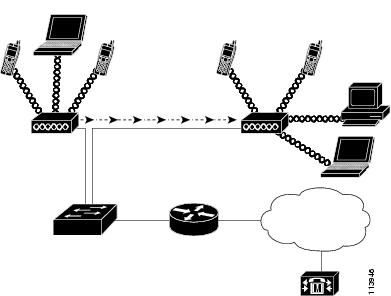
Figure 2-1 shows a typical WLAN topology that enables the wireless transmission of voice for wireless IP telephony.
Figure 2-1 WLAN with Wireless IP Phones
When a wireless IP phone powers on, it searches for and becomes associated with an AP. As users move from one location to another, the wireless IP phone roams out-of-range of one AP into the range of another AP. The wireless IP phone builds and maintains a list of eligible APs and reconnects to an AP in that list. See "Associating to APs" section for more information.
The AP uses its connection to the wired network to transmit data and voice packets to and from the switches and routers. Voice signaling is transmitted to the Cisco Unified Communications Manager server for call processing and routing.
APs are critical components in a WLAN because they provide the wireless links or "hot spots" to the network. Cisco requires that the APs supporting voice communications use Cisco IOS Release 12.3(8)JA or later. Cisco IOS software provides features for managing voice traffic.
In some WLANs, each AP has a wired connection to an Ethernet switch, such as a Cisco Catalyst 3750, that is configured on a LAN. The switch provides access to gateways and the Cisco Unified Communications Manager server to support wireless IP telephony.
Some networks have wired components that support wireless components. The wired components could consist of switches, routers, and bridges with special modules to enable wireless capability.
The Cisco Unified WLAN can have the following components:
•
•
•
•
•
•
•
•
•
•
For more information about Cisco Unified Wireless Networks, refer to http://www.cisco.com/en/US/products/hw/wireless/index.html
Understanding WLAN Standards and Technologies
This section describes the following concepts:
•
•
•
•
802.11 Standards for WLAN Communications
Wireless LANs must follow the Institute of Electrical and Electronics Engineers (IEEE) 802.11 standards that define the protocols that govern all Ethernet-based wireless traffic. The Cisco Unified Wireless IP Phone 7925G supports the following standards:
•
•
•
•
Radio Frequency Ranges
WLAN communications use the following RF ranges:
•
Many devices operate in the 2.4 GHz bandwidth including cordless phones and microwave ovens and can interfere with wireless communications. Interference does not destroy the signal, but can reduce the transmission speed from 11 Mbps to 1 Mbps. RF interference can affect voice quality over the wireless network.
•
Table 2-1 lists frequency band ranges and operating channels by regulatory domain.
802.11 Data Rates, Tx Power, Ranges, and Decibel Tolerances
Table 2-2 lists the Tx power capacities, data rates, ranges in feet and meters, and decibels tolerated by the receiver by 801.11 standard.
Table 2-2 Tx Power, Data Rates, Ranges, and Decibels by Standard
40mW
6 Mbps
610 ft (186 m)
-89 dBm
9 Mbps
610 ft (186 m)
-88 dBm
12 Mbps
558 ft (170 m)
-86 dBm
18 Mbps
541 ft (165 m)
-85 dBm
24 Mbps
508 ft (155 m)
-82 dBm
36 Mbps
426 ft (130 m)
-80 dBm
48 Mbps
328 ft (100 m)
-76 dBm
54 Mbps
295 ft (90 m)
-74 dBm
40mW
6 Mbps
722 ft (220 m)
-90 dBm
9 Mbps
656 ft (200 m)
-89 dBm
12 Mbps
623 ft (190 m)
-87 dBm
18 Mbps
623 ft (190 m)
-85 dBm
24 Mbps
623 ft (190 m)
-82 dBm
36 Mbps
492 ft (150 m)
-78 dBm
48 Mbps
410 ft (125 m)
-74 dBm
54 Mbps
394 ft (120 m)
-73 dBm
50mW
1 Mbps
1,027 ft (313 m)
-95 dBm
2 Mbps
951 ft (290 m)
-89 dBm
5.5 Mbps
853 ft (260 m)
-89 dBm
11 Mbps
787 ft (240 m)
-85 dBm
1 Adjusts dynamically when associating with an AP if the AP client setting is enabled.
2 Advertised rates by the APs are used. If the Restricted Data Rates functionality is enabled in the Cisco Unified Communications Manager Administration phone configuration, then the Traffic Stream Rate Set IE (CCX V4) is used.
Wireless Modulation Technologies
Wireless communications uses the following modulation technologies for signaling:
•
•
Table 2-3 provides a comparison of data rates, number of channels, and modulation technologies by standard.
AP, Channel, and Domain Relationships
APs transmit and receive RF signals over channels within the 2.4 GHz or 5.1 to 5.8 GHz frequency band. To provide a stable wireless environment and reduce channel interference, you must specify non-overlapping channels for each AP. The recommended channels for 802.11b and 802.11g in North America are 1, 6, and 11.
Regulatory domains determine the number of channels that wireless communications can use within the frequency band. Table 2-1 lists the frequency ranges, operating channels, and product numbers for four regulatory domains. The Cisco Unified Wireless IP Phone 7925G uses the fourth domain for all other regions in the world. Wireless LANs in the rest of the world use 802.11d to identify band ranges and channels.
Note
The AP coverage area depends on its type of antenna and transmission power. The AP coverage range is from 500 to 1000 feet with effective isotropic radiated power (EIRP) output that scales at 1, 5, 20, and 50 mW. To provide effective coverage, APs need a range overlap of approximately 20 percent to allow uninterrupted connections as phone users roam from one AP to another.
Wireless networks use a service set identifier (SSID). The SSID differentiates one WLAN from another, so all APs and all devices attempting to connect to a specific WLAN must use the same SSID. The SSID groups user devices and associates the group with the APs.
For more information about wireless network components and design, refer to the Overview: Cisco Unified Wireless Network at http://www.cisco.com/en/US/solutions/ns175/networking_solutions_products_genericcontent0900aecd80529a5f.html.
For more information about APs, see the "VoIP WLAN Configuration" section.
WLANs and Roaming
Wireless IP phones provide communication mobility to users within the WLAN environment. Unlike cellular phones that have broad coverage, the coverage area for the wireless IP phone is smaller; therefore, phone users frequently roam from one AP to another. To understand some of the limitations of roaming with wireless IP phones, these examples provide information about the WLAN environment.
•
Note
•
If the wireless IP phone user moves from an AP that covers IP Subnet A to an AP that covers IP Subnet B, the phone no longer has an IP address or gateway that is valid within the new subnet and the call can disconnect.
•
http://www.cisco.com/univercd/cc/td/doc/product/lan/cat6000/cfgnotes/wlsm_1_1/index.htm
Layer 3 roaming with lightweight mode APs is accomplished by controllers that use dynamic interface tunneling. Clients that roam across controllers and VLANS can keep their IP address when using the same SSID.
•
CCKM, a centralized key management protocol, provides a cache of session credentials on the wireless domain server (WDS). As the phone roams from one AP to the next, CCKM compresses the number of message exchanges during roaming by providing a master key stored on the WDS for the AP to use. The reassociation exchange is reduced to two messages, thereby reducing the roaming time.
For details about CCKM, refer to the "Cisco Fast Secure Roaming Application Note" at:
http://www.cisco.com/en/US/products/hw/wireless/ps4570/prod_technical_reference09186a00801c5223.html
Note
Related Topics
•
•
Bluetooth Wireless Technology
Bluetooth Class 2.0 with Extended Data Rate (EDR) is a short-range wireless technology that is supported by the Cisco Unified Wireless IP Phone 7925G. It supports the Hands-Free Profile version 1.5.
Your Cisco Unified Wireless IP Phone 7925G is a qualified Bluetooth wireless device (Qualified Device ID (QDID) B014396) and provides voice communication over the same wireless LAN that your computer uses.
Bluetooth enables low bandwidth wireless connections within a range of 10 meters. The best performance is in the 1 to 2 meter range. Synchronous voice channels are provided by using circuit switching and asynchronous data channels are provided by using packet switching.
Bluetooth wireless technology operates in the 2.4 GHz band which is the same as the 802.11b/g band. There can be a potential interference issues. It is recommended that you:
•
•
•
Pairing Headsets
The Cisco Unified Wireless IP Phone 7925G pairs with headsets using a shared key authentication and encryption method. The authentication process can require a personal identification number (PIN) specific to the headset, commonly "0000." The Cisco Unified Wireless IP Phone 7925G can be paired with more than one headset at a time. Pairing is typically performed once for each headset.
Once a device has been paired, its Bluetooth connection is maintained as long as both devices (phone and headset) are enabled and within range of each other. The connection re-establishes itself automatically if either of the devices powers down then powers up. The green-dotted Bluetooth icon indicates whether or not a device is connected.
When headsets are more than 10 meters away from Cisco Unified Wireless IP Phone 7925G, Bluetooth drops the connection after a 15 to 20 second timeout. If the paired headset comes back into range of the Cisco Unified Wireless IP Phone 7925G and the phone is not connected to another Bluetooth headset, then the in-range Bluetooth headset automatically reconnects. For certain phone types that operate in power-save modes, the user may have to "wake-up" the headset by tapping on its operational button to initiate the reconnect.
Note
Components of the VoIP Wireless Network
The wireless IP phone must interact with several network components in the WLAN to successfully place and receive calls. The following topics describe network components:
•
•
•
•
•
Networking Protocols Used with Cisco Unified Wireless IP Phones
Cisco Unified IP Phones support several networking protocols for voice communication. Table 2-4 describes the networking protocols that the Cisco Unified Wireless IP Phone 7925G supports.
Related Topics
•
•
•
Interacting with Cisco Unified Wireless APs
Wireless IP phones use the same APs as wireless data devices. However, voice traffic over a WLAN requires different equipment configurations and layouts than a WLAN that is used exclusively for data traffic. Data transmission can tolerate a higher level of RF noise, packet loss, and channel contention than voice transmission. Packet loss during voice transmission can cause choppy or broken audio and make the phone call inaudible.
Wireless IP Phones users are mobile and often roam across a campus or between floors in a building while connected to a call. In contrast, data users remain in one place or occasionally move to another location. The ability to roam while maintaining a call is one of the advantages of wireless voice so RF coverage needs to include stairwells, elevators, quiet corners outside conference rooms, and passage ways.
To ensure good voice quality and optimal RF signal coverage, you must perform a site survey. The site survey will determine settings suitable to wireless voice and assist in the design and layout of the WLAN; for example AP placement, power levels, and channel assignments.
After deploying and using wireless voice, you should continue to perform post installation site surveys. When you add a group of new users, install more equipment, or stack large amounts of inventory, you are changing the wireless environment. A post installation survey will verify that the AP coverage is still adequate for optimal voice communications. See the "Site Survey Verification" section for more information.
Associating to APs
At startup, the Cisco Unified Wireless IP Phone 7925G scans for APs with SSIDs and encryption types that it recognizes. The phone builds and maintains a list of eligible APs and uses the following variables to determine the best AP.
•
•
Note
•
The wireless IP phone associates with the AP with the highest RSSI and lowest channel usage values (QBSS) that have matching SSID and encryption types.To ensure that voice traffic is handled properly, you must configure the correct QoS in the AP. For configuration information, see "Wireless Network Requirements for VoIP" section.
Related Topics
•
Voice QoS in a Wireless Network
Voice traffic on the Wireless LAN, like data traffic, is susceptible to delay, jitter, and packet loss. These issues do not impact the data end user, but have serious implications for a voice call. To ensure that voice traffic receives timely and reliable treatment with low delay and low jitter, you must use Quality of Service (QoS), and use separate virtual LANs (VLANs) for voice and data. By isolating the voice traffic onto a separate VLAN, you can use QoS to provide priority treatment for voice packets when traveling across the network. Also, use a separate VLAN for data traffic, not the default native VLAN which is typically used for all network devices.
You need the following VLANs on the network switches and the APs that support voice connections on the WLAN.
•
•
•
Assign separate SSIDs to the voice and to the data VLANs. If you configure a separate management VLAN in the WLAN, do not associate an SSID with the management VLAN.
By separating the phones into a voice VLAN and marking voice packets with higher QoS, you can ensure that voice traffic gets priority treatment over data traffic resulting in lower packet delay and fewer lost packets.
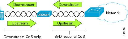
Unlike wired networks with dedicated bandwidths, wireless LANs consider traffic direction when implementing QoS. Traffic is classified as upstream or downstream from the point of view of the AP as shown in Figure 2-2.
Figure 2-2 Voice Traffic in a Wireless Network
Beginning with Cisco IOS release 12.2(11)JA, Cisco Aironet APs support the contention-based channel access mechanism called Enhanced Distributed Coordination Function (EDCF). The EDCF-type of QoS has up to eight queues for downstream (toward the 802.11b/g clients) QoS. You can allocate the queues based on these options:
•
•
•
•
Although you can have up to eight queues on the AP, you should use only two queues for voice traffic to ensure the best possible voice QoS. Place voice (RTP) and signaling (SCCP) traffic in the highest priority queue, and place data traffic in a best-effort queue.Although 802.11b/g EDCF does not guarantee that voice traffic is protected from data traffic, you should get the best statistical results by using this queuing model.
Note
To improve reliability of voice transmissions in a nondeterministic environment, the Cisco Unified Wireless IP Phone 7925G supports the IEEE 802.11e industry standard and is Wi-Fi Multimedia (WMM) capable. WMM enables differentiated services for voice, video, best effort data and other traffic. However, in order for these differentiated services to provide sufficient QoS for voice packets, only a certain amount of voice bandwidth can be serviced or admitted on a channel at one time. If the network can handle "N" voice calls with reserved bandwidth, when the amount of voice traffic is increased beyond this limit, (to N+1 calls), the quality of all calls suffers.
To help address the problems of VoIP stability and roaming, an initial Call Admission Control (CAC) scheme is required. With CAC, QoS is maintained in a network overload scenario by ensuring that the number of active voice calls does not exceed the configured limits on the AP. The Cisco Unified Wireless IP Phone 7925G can integrate layer 2 TSpec admission control with layer 3 Cisco Unified Communications Manager admission control (RSVP). During times of network congestion, calling or called parties receive a fast busy indication. The system maintains a small bandwidth reserve so wireless phone clients can roam into a neighboring AP (AP), even when the AP is at "full capacity". After reaching the voice bandwidth limit, the next call is load-balanced to a neighboring AP without affecting the quality of the existing calls on the channel.
Implementing QoS in the connected Ethernet switch is highly desirable to maintain good voice quality. The COS and DSCP values that the Cisco Unified Wireless IP Phone 7925G sets do not need to be modified. To configure QoS correctly on the AP, see the "Wireless Network Requirements for VoIP" section.
Related Topics
•
Interacting with Cisco Unified Communications Manager
Cisco Unified Communications Manager is the call control component in the network that handles and routes calls for the wireless IP phones. Cisco Unified Communications Manager manages the components of the IP telephony system—the phones, access gateways, and the resources—for such features as call conferencing and route planning. When deploying Cisco Unified Wireless IP Phone 7925G, you must use Cisco Unified Communications Manager Release 4.1, 4.2, 4.3, 5.1, 6.0(1), 6.1(1) or 7.0(1) and SCCP protocol.
Before Cisco Unified Communications Manager can recognize a phone, it must register with Cisco Unified Communications Manager and be configured in the database. For information about setting up phones in Cisco Unified Communications Manager, see the "Overview of Configuring and Installing the Cisco Unified Wireless IP Phone 7925G" section on page 1-14.
You can find more information about configuring Cisco Unified Communications Manager to work with the IP phones and IP devices in the Cisco Unified Communications Manager Administration Guide and Cisco Unified Communications Manager System Guide.
Related Topics
•
•
Phone Configuration Files and Profile Files
Configuration files for a phone define parameters for connecting to Cisco Unified Communications Manager and are stored on the TFTP server. In general, any time you make a change in Cisco Unified Communications Manager Administration that requires resetting the phone, the phone configuration file changes automatically.
Configuration files also contain information about the correct image load for the phone. If this image load differs from the one currently loaded on a phone, the phone contacts the TFTP server to request the new image file.
The phone first requests the configuration file SEPxxxxxxxxxxxx.cnf.xml, where each xx is the two-digit lowercase hexadecimal representation of each integer in the MAC address. If the phone cannot find this file, it requests the configuration file XMLDefault.cnf.xml.
After the phone obtains the *.cnf.xml files, it requests a phone-specific profile file. If a phone cannot find this profile file, it requests the appropriate common profile file.
After the phone finds one of the profile files, or if it cannot find a profile file, it continues with its startup process.
Related Topic
Understanding the Phone Startup Process, page 3-17
Interacting with the Dynamic Host Configuration Protocol Server
Dynamic Host Configuration Protocol (DHCP) is a communications protocol that lets network administrators manage and automate the assignment of IP addresses in a network. When an IP device is added to the network, it must have a unique IP address. Without DHCP, the IP address must be entered manually at each device. DHCP allocates IP addresses dynamically and reuses IP addresses when devices no longer need them.
If DHCP is enabled in the network, the Cisco Unified Wireless IP Phone 7925G uses the DHCP scope settings in the DHCP server to perform the phone provisioning bootup process. You must configure the settings of the DHCP server in the Cisco Unified Communications Manager network.
The DHCP scope settings include the following:
•
•
•
The priority of the DHCP settings for the TFTP server is unique to the Cisco Unified Wireless IP Phone 7925G, as shown in Table 2-5.
Table 2-5 DHCP Settings Priority
1st
DHCP option 150
2nd
DHCP option 66
3rd
SIADDR
4th
ciscoCM1
If DHCP is disabled, the Cisco Unified Wireless IP Phone 7925G uses the following network settings in Table 2-6 to perform the phone provisioning bootup process. You must configure these static parameters for each Cisco Unified Wireless IP Phone 7925G.
Security for Voice Communications in WLANs
Because all WLAN devices that are within range can receive all other WLAN traffic, securing voice communications is critical in WLANs. To ensure that voice traffic is not manipulated or intercepted by intruders, the Cisco Unified Wireless IP Phone 7925G and Cisco Aironet APs are supported in the Cisco SAFE Security architecture. For more information about security in networks, refer to http://www.cisco.com/en/US/netsol/ns744/networking_solutions_program_home.html.
This section contains the following items:
•
Authentication Methods
The Cisco Wireless IP telephony solution provides wireless network security that prevents unauthorized logins and compromised communications by using the following authentication methods.
•
•
Shared key authentication can be less secure than open authentication with WEP because someone can monitor the challenges. An intruder can calculate the WEP key by comparing the unencrypted and encrypted challenge text strings.
•
•
The TLS tunnel uses Protected Access Credentials (PACs) for authentication between the client (phone) and the RADIUS server. The server sends an Authority ID (AID) to the client (phone), which in turn selects the appropriate PAC. The client (phone) returns a PAC-Opaque to the RADIUS server. The server decrypts the PAC with its master-key. Both end points now have the PAC key and a TLS tunnel is created. EAP-FAST supports automatic PAC provisioning, but you must enable it on the RADIUS server.
Note
•
Microsoft Windows XP provides support for 802.1x, allowing EAP authentication protocols (including EAP-TLS) to be used for authentication. The authentication used in EAP-TLS is mutual: the server authenticates the user and the user authenticates the server. Mutual authentication is required in a WLAN. EAP-TLS provides excellent security but requires client certificate management.
EAP-TLS uses Public Key Infrastructure (PKI) with the following conditions:
–
–
–
•
•
The exchange of authentication information is encrypted and the user credentials are safe from eavesdropping. MS-CHAP v2 is the supported inner authentication protocol.
•
This section describes the following concepts:
Authenticated Key Management
The following authentication schemes use the RADIUS server to manage authentication keys:
•
•
With WPA and CCKM, encryption keys are not entered on the phone, but are automatically derived between the AP and phone. But the EAP username and password that are used for authentication must be entered on each phone.
Encryption Methods
To ensure that voice traffic is secure, the Cisco Unified Wireless IP Phone 7925G supports WEP, TKIP, and Advanced Encryption Standards (AES) for encryption. When using these mechanisms for encryption, both the signaling Skinny Client Control Protocol (SCCP) packets and voice Real-Time Transport Protocol (RTP) packets are encrypted between the AP and the wireless IP phone.
•
EAP and CCKM authentication can use WEP keys for encryption. The RADIUS server manages the WEP key and passes a unique key to the AP after authentication for encrypting all voice packets; consequently, these WEP keys can change with each authentication.
•
•
Note
Choosing AP Authentication and Encryption Methods
Authentication and encryption schemes are setup within the wireless LAN. VLANS are configured in the network and on the APs and specify different combinations of authentication and encryption. An SSID is associated with a VLAN and its particular authentication and encryption scheme. In order for wireless client devices to authenticate successfully, you must configure the same SSIDs with their authentication and encryption schemes on the APs and on the wireless IP phone.
Some authentication schemes require specific types of encryption. With Open authentication, you have the option to use static WEP for encryption for added security. But if you are using Shared Key authentication, you must set static WEP for encryption, and you must configure a WEP key on the phone.
When using Authenticated Key Management (AKM) for the Cisco Unified Wireless IP Phone 7925G, several choices for both authentication and encryption can be set up on the APs with different SSIDs. When the phone attempts to authenticate, it chooses the AP that advertises the authentication and encryption scheme that the phone can support. Auto (AKM) mode can authenticate by using WPA, WPA2, WPA Pre-shared key, or CCKM.
Note
•
•
•
•
•
Table 2-7 provides a list of authentication and encryption schemes configured on the Cisco Aironet APs supported by the Cisco Unified Wireless IP Phone 7925G. The table shows the network configuration option for the phone that corresponds to the AP configuration.
For additional information about Cisco WLAN Security, refer to http://www.cisco.com/en/US/products/hw/wireless/ps430/prod_brochure09186a00801f7d0b.html
For more information about configuring authentication and encryption schemes on APs, refer to the Cisco Aironet Configuration Guide for your model and release at this URL:
Related Topics
•
•
•
VoIP WLAN Configuration
This section provides configuration guidelines for deploying wireless IP phones in the WLAN and includes these topics:
•
Wireless Network Requirements for VoIP
The Cisco Unified Wireless IP Phone 7925G supports Cisco Aironet APs (APs) that can run Cisco IOS in autonomous mode and APs that run in lightweight mode with lightweight AP protocol (LWAPP) and use a Cisco Unified wireless LAN controller. Table 2-8 lists the supported AP models and operation mode in the WLAN.
When configuring VoWLAN, use APs that run Cisco IOS Release 12.3(8)JA or later. It is recommended that Cisco Aironet 1130AG, 1240AG, 1250 series APs run Cisco IOS Release 12.3(4g)JA1 or later.
Controllers should be running version 4.0217.0 (minimum) or version 4.2.61.0 or later, which is recommended. The controllers should have Cisco IOS Release 12.3(8)JX or later configured also.
Note
Note
Configuring the Wireless Network for Voice
This section identifies key AP configuration options that are required for optimal voice performance. This is not a complete list of configuration steps or options for deploying APs such as the Cisco Aironet APs. For more information about configuring your AP, refer to the appropriate Cisco Aironet AP installation and configuration guide for your model or the documentation for your AP.
Note
To see a list of configuration tasks for the Cisco Aironet AP, controller, and Ethernet switch when setting up VoIP on the WLAN, see the "Configuring a Wireless Network" section on page D-1.
Configuration Tip for Cisco Aironet APs
If you are using EAP-FAST, you must increase the EAP request (802.1x) timeout to at least 20 seconds to ensure that the phone gets the PAC credentials successfully.
To change the request timeout on the controller, follow these steps:
Procedure
Step 1
Step 2
Step 3
Step 4
Site Survey Verification
Before the initial deployment of wireless phones in the WLAN, it is recommended that a site survey is performed to verify that the APs are providing adequate coverage and that wireless phones can roam from one AP to another with no audio problems. After the initial deployment, it is a good practice to perform site surveys at regular intervals to ensure continued coverage and roaming.
From the Cisco Unified Wireless IP Phone 7925G, you can use the Neighbor List utility or Site Survey utility from the SETTINGS > Status menu.
The Neighbor List utility provides information about the current AP and the closest neighbors tracked by the phone. For more information see Using the Neighbor List Utility.
The Site Survey utility produces a report, written as a temporary HTML file, upon termination of the survey. This Site Survey Report is accessible from the phone web page for viewing or forwarding to Cisco TAC for troubleshooting purposes. For more information, see Using the Site Survey Utility.
You should use the wireless IP phone and the Aironet Client Utility (ACU) to verify that the signal range and transmission power provide adequate coverage for roaming phones.
Use the following topics for information about performing the site survey:
•
•
•
Performing a Site Survey Verification
Perform these tasks to verify wireless voice network operation. Check that the wireless IP phones:
1.
2.
3.
4.
5.
6.
After phones are installed, request that users report any problems when using their wireless IP phones.
When you perform a site survey verification and encounter problems, see the Chapter 10, "Troubleshooting the Cisco Unified Wireless IP Phone 7925G" for assistance with finding the cause of the problem.
Related Topics
•
•
Using the Neighbor List Utility
The Neighbor List utility displays a list of the current AP and the closest neighbors tracked by the phone. The phone typically does not scan while it is idle, so often there is only one entry, which is the currently associated AP, in the list.
To use the Neighbor List utility, follow these steps:
Procedure
Step 1
Step 2
Step 3
The phone displays the current AP and the closest neighbors. For example:
SSID: abcd
Step 4
SSID: abcdChannel:06BSSID: 00:13:1a:16:cf:d0RSSI:-51CU:38Step 5
Step 6
Using the Site Survey Utility
The Site Survey utility is used to actively and passively scan the wireless medium across all channels and locate APs that belong to the Basic Service Set (BSS). The results of the scans are then used help to identify areas of low coverage, if any, and to determine whether the APs are configured consistently as recommended in the Cisco deployment guidelines.
When you start the Site Survey utility, the phone disassociates from the current AP and remains disassociated for the duration of the operation.
For more information, see Viewing the Site Survey Report on the Web, page 4-38.
Caution
To use the Site Survey utility, follow these steps:
Procedure
Step 1
Step 2
Step 3
The phone displays a list of APs within range that have the same SSID and security settings as the phone. To see more information about an AP, scroll to the desired line and press Details.
Step 4
Step 5
Step 6
In addition to the Site Survey utility in the Cisco Unified Wireless IP Phone 7925G, you can also use the Cisco Aironet Client Utility Site Survey Utility from a laptop PC. Refer to the section on "Performing a Site Survey" in the Cisco Aironet Wireless LAN Client Adapters Installation and Configuration Guide for your system.
Related Topics
•