Feedback
Table Of Contents
QoS Guidelines for the Cisco MXE Video Interoperability Solution
Manual Capacity Planning for Video Interoperability Calls
Manual Capacity Planning and Configuration Example
Differentiated Services (DiffServ)
Cisco MXE 5600 QoS Configuration
About DSCP Marking on the Cisco MXE 5600
About Bandwidth Limits on the Cisco MXE 5600
Recommendations for Calculating Required Bandwidth
Recommended QoS Settings for Endpoints
QoS Settings for Cisco TelePresence System
QoS Settings for Supported Videoconferencing Endpoints
QoS Guidelines for the Cisco MXE Video Interoperability Solution
Revised: June 3, 2011This chapter provide guidelines for configuring quality of service (QoS).
•
Manual Capacity Planning for Video Interoperability Calls
•
Manual Capacity Planning for Video Interoperability Calls
Manual capacity planning relies on having sufficient bandwidth within the network to support the maximum number of licensed video interoperability calls that can occur simultaneously. The physical topology of the network infrastructure impacts how much and where bandwidth needs to be provisioned. To minimize the overall bandwidth requirement, we recommended that you deploy Cisco MXE 5600s close—in terms of network connectivity—to the CTMS for static or scheduled conference calls and close to the Cisco TelePresence Systems for point-to-point calls. In general, for point-to-point calls in which a choice has to be made between being close to a Cisco TelePresence System or close to a videoconferencing endpoint, it is better to be close to the Cisco TelePresence System because the media stream between Cisco MXE 5600 and the videoconferencing endpoint is often less than the media stream between the Cisco MXE 5600 and Cisco TelePresence System.
Manual Capacity Planning and Configuration Example
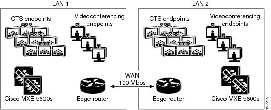
Figure 3-1 shows two campuses, each with its own LAN, connected via a 100 Mbps WAN link. Each campus has many Cisco TelePresence Systems and videoconferencing endpoints, as well as a pool of Cisco MXE 5600s to enable video interoperability calls.
Figure 3-1 Example Two-Campus Deployment for Manual Capacity Planning
There must be sufficient network capacity for each of the following types of video interoperability calls:
•
•
•
The total available WAN bandwidth is 500 Mbps. WAN bandwidth is generally more restricted than LAN bandwidth, so this example focuses on the capacity planning for the WAN bandwidth and includes the following assumptions:
•
•
•
•
•
Based on these assumptions, the following network and Cisco MXE 5600 capacity configuration is suggested for this example:
•
•
•
QoS Tools
QoS technologies refer to the set of tools and techniques to manage network resources, such as bandwidth, latency, jitter, and loss. QoS technologies allow different types of traffic to intelligently contend for network resources. For example, real-time voice and video may be granted strict priority service, while some critical data applications may receive (non-priority) preferential service, and some undesired applications may be assigned deferential levels of service. Therefore, QoS is a critical element for the successful network convergence of voice, video, and data.
This section discusses the following tools used to implement QoS for videoconferencing over an enterprise WAN:
•
Traffic Classification
Before traffic can be handled according to its unique requirements, it must be identified or labeled by using Differentiated Services Code Point (DSCP). For more information about classification, see the following sections:
•
In many cases, traffic classification is done at the edge of the network by the video endpoint or an Ethernet switch, such as the Catalyst 6000. In these cases, the trust boundary is extended to the edge of the enterprise network and resides in the access or distribution layer.
In some cases, however, the ability to classify and define a trust boundary at the edge of the network might not exist, such as in a branch with Ethernet switches and video endpoints that cannot classify traffic. In this situation, you can implement the trust boundary and classification on the router itself by using ACL entries for small sites without a gatekeeper or by using the Border Element in larger branch sites that contain a gatekeeper. For more information, see the "Border Element Usage" section.
Differentiated Services (DiffServ)
DiffServ is used to classify packets as they enter the local network. This classification applies to the flow of traffic, where a flow is defined by the following five elements:
•
•
•
•
•
A flow that has been classified, or marked, can then be acted upon by other QoS mechanisms. Multiple flows can be dealt with in a multitude of ways, depending on the requirements of each flow. Packets are first classified according to their current Differentiated Services Code Point (DSCP) values. Then, they are separated into queues where one queue may be routed via a marking mechanism and another queue may be examined more closely. After further examination, additional packets may be sent for marking or sent directly to the shaping/dropping mechanisms, where all packets end up before leaving the interface.
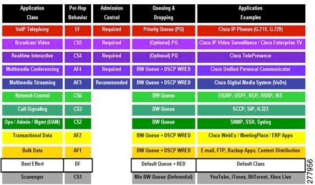
Figure 3-2 shows the DiffServ classes.
Figure 3-2 Figure 1 - RFC 4594 Configuration Guidelines for DiffServ Classes
Table 3-1 describes the mapping between class, DSCP, and IP precedence.
DSCP Marking
H.323 endpoints are generally treated as not trusted. Classification and the corresponding DSCP marking is done by the first hop switches via ACLs based on a range of media ports. The H.323 media port range is about 20 ports wide. All H.323 endpoints must be configured to use this range for proper classification to occur.
Cisco Unified Communications SIP endpoints that are registered with CUCM , Cisco TelePresence endpoints, both Cisco TelePresence Systems and CTMS, are generally trusted to mark their own DSCP values appropriately. Cisco TelePresence Systems and CTMS endpoints must be configured with the appropriate DSCP values for proper classification to occur.
Note, it is possible for both classes to use the same DSCP values, but the flexibility is provided for each to use its own values.
Class Assignment
Within Cisco TelePresence, traffic is assigned to one class and placed within its own queue. Video conference traffic is assigned a different class and placed with a separate queue. It is possible for both to be assigned to the same class, but the flexibility is provided for each to be assigned its own class.
Note
In terms of link bandwidth, the Cisco TelePresence queue is generally allocated about 50% of the total bandwidth, and the video queue is allocated about 10% of the total bandwidth. For both LAN and WAN links, class based weighted fair queuing is used with an individual media stream being kept entirely within a single queue in order to avoid timing and synchronization issues.
In general, both audio and video are placed in the same queue. This is the recommended practice as it helps maintain synchronization of the audio with the video. Note that we therefore recommend using the same DSCP marking (i.e. CS4) for both the audio and the video.
It is possible, or course, to mark the audio and video differently, and to have them assigned to different queues, but that is not recommended in general.
Border Element Usage
In the multi-zone WAN model, we recommend that you use the Border Element whenever possible. The Border Element allows the classification or reclassification of video streams. The Border Element also provides a single access point for the priority queue to keep unauthorized video streams from oversubscribing the priority queue. H.323 video endpoints must be registered with the gatekeeper to obtain access to the Border Element. The gatekeeper is configured for a maximum video bandwidth allowed outside its local zone. This maximum bandwidth should match the amount of bandwidth provisioned for the priority queue to ensure proper queuing functionality.
Cisco MXE 5600 QoS Configuration
The Cisco MXE supports two mechanisms that enable quality of service (QoS) for video interoperability calls: setting appropriate DSCP values and per-call bandwidth limits.
•
•
•
About DSCP Marking on the Cisco MXE 5600
By default, the Cisco MXE 5600 marks all signaling and media packets with appropriate DSCP values as specified in RFC 4595.
The SIP interface configuration determines the DSCP value that Cisco MXE 5600 sets on all SIP signaling packets it sends. By default, the DSCP value is CS3 in accordance with the Cisco QoS recommendation for call signaling.
Cisco MXE determines the appropriate DSCP values for the media that it sends on a per-packet basis and bases it on the DSCP value of the corresponding media packets that it receives. Whatever DSCP value is set on the media packets that Cisco MXE 5600 receives from an endpoint is used for the media packets that Cisco MXE 5600 sends to that same endpoint. For example, if the Cisco MXE 5600 receives from media from a Cisco TelePresence System that is marked as DSCP CS4 and media that is marked as AF41 from a videoconferencing endpoint, the transcoded media that Cisco MXE 5600 sends to the Cisco TelePresence System is marked as DSCP CS4, and the transcoded media Cisco MXE sends to the videoconferencing endpoint is marked with AF41.
For video interoperability calls, we recommend that you configure the Cisco TelePresence System and videoconferencing endpoints to mark the media as DSCP CS4 in accordance with the Cisco QoS recommendation for real-time interactive media. When configuring the endpoints is not feasible or desirable, you can configure the first hop switch or a router in the media path to set the DSCP on behalf of the endpoint.
About Bandwidth Limits on the Cisco MXE 5600
The Cisco MXE 5600 supports configurable limits per media stream. This is accomplished by configuring the stream profile. When you define a stream profile, you can specify a bandwidth limit.
This is the highest bandwidth that the Cisco MXE 5600 will negotiate to receive. Cisco TelePresence requires symmetric bandwidth: whatever limit is used for receiving is used also for sending. For videoconferencing endpoints, the Cisco MXE 5600 honors the requested bandwidth limits and assumes appropriate bandwidth is allocated to the network.
Note
Example 3-1 shows a stream profile that specifies bandwidth limits. In this example, the Cisco MXE 5600 asks to receive no more than 2.75Mbps for video and 128kbps for audio. These values can be customized to match deployment requirements.
Example 3-1 Bandwidth Limits in a Stream Profile
stream-profile 1app-muxbandwidth 2250000codec-profile 1description Default TelePresence video streammode sendrecvtype videostream-profile 2app-muxbandwidth 128000codec-profile 2 preference 1codec-profile 4 preference 2description Default TelePresence audio streammode sendrecvRecommendations for Calculating Required Bandwidth
For QoS implementation, you need to consider the Cisco MXE-OS device's video and audio bandwidth limits for videoconferencing (VC) endpoints and Cisco TelePresence System (CTS) endpoints. These values are configured in stream profiles (see About Bandwidth Limits on the Cisco MXE 5600) and may be adjusted to meet the requirements of individual solutions. To calculate the bandwidths required for point-to-point and multipoint calls, use the following suggested formulas.
Note
Point-to-Point Bandwidth
= CTS-to-MXE + VC-to-MXE
Multipoint Bandwidth
= CTS-to-MXE + VC-to-MXE + CTMS-to-MXE
where
CTS-to-MXE
= Number of CTS units x bandwidth for each CTS
VC-to-MXE
= Number of VCs x bandwidth for each VC
CTMS-to-MXE
= Number of CTMS units x bandwidth for each CTMS
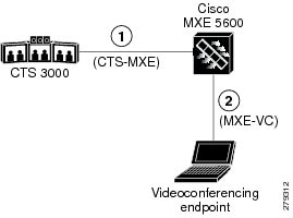
Figure 3-3 displays a schematic of the point-to-point bandwidth requirements formula. In this schematic, the videoconferencing endpoint is a laptop running Microsoft Communicator with CUCIMOC; in general, the requirements apply to all videoconferencing endpoints.
Figure 3-3
Point-to-Point Bandwidth Requirements
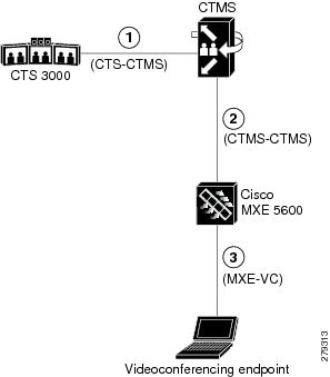
Figure 3-4 displays a schematic of multipoint bandwidth requirements.formula. In this schematic, the videoconferencing endpoint is a laptop running Microsoft Communicator with CUCIMOC; in general, the requirements apply to all videoconferencing endpoints.
Figure 3-4
Multipoint Bandwidth Requirements
Table 3-2 Video and Audio Bandwidth Ranges Per Component Unit
CTS and CTMS
1000k to 2250k1
up to 128k
Cisco WebEx client
304k for CIF plus up to 450k for presentation video2
Up to 64k
Videoconferencing endpoint (H.3233 or SIP)
320k to 1920
up to 64k
1 SIP messaging may show a total of 2750k for an additional, but unused, audio presentation channel.
2 Per meeting bandwidth utilization over tunnel.
3 We recommend that the minimum bandwidth for an H.323 endpoint be 384 kbps or higher so that video bandwidth is at least 322 kbps to ensure reasonable quality video; otherwise, video artifacts may appear.
Recommended QoS Settings for Endpoints
This section includes the following topics:
•
•
QoS Settings for Cisco TelePresence System
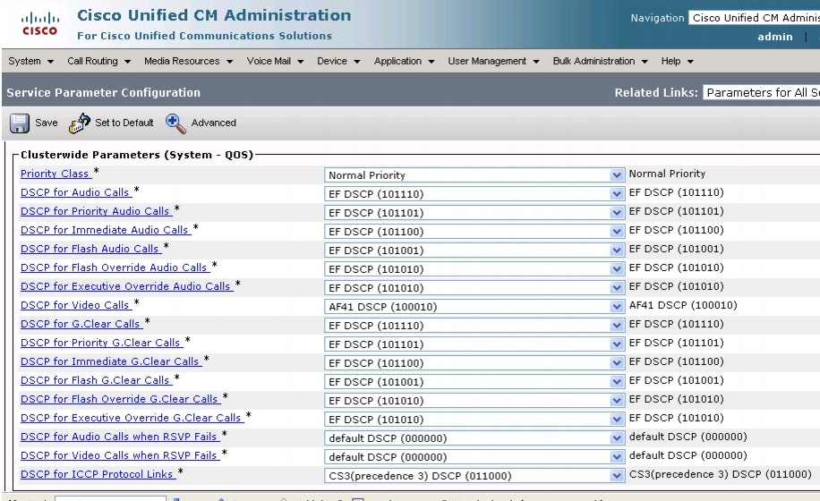
You configure QoS settings for Cisco TelePresence System in Cisco Unified Communications Manager.
Figure 3-5 shows the recommended QoS settings for Cisco TelePresence Systems.
For information on configuring QoS in a Cisco TelePresence solution, see Quality of Service Design for TelePresence at the following URL:
http://www.cisco.com/en/US/docs/solutions/Enterprise/Video/tpqos.html
Tip
Figure 3-5 Cisco Unified Communications Manager QoS Configuration Screen
QoS Settings for Supported Videoconferencing Endpoints
We recommend that you configure the following QoS settings for supported videoconferencing endpoints:
•
•
Call Admission Control
Call admission control, or bandwidth control, ensures that the network resources are not oversubscribed. Calls that exceed the specified bandwidth limit are rejected to ensure video quality.
Currently, the Cisco TelePresence Solution does not provide an automated mechanism for reserving network bandwidth or performing call-by-call Call Admission Control (CAC). Because locations-based CAC and Resource Reservation Protocol (RSVP), as administered by Cisco Unified Communications Manager, are not recommended or supported for the Cisco TelePresence Solution, we do not support these CAC techniques for the Cisco MXE Video Interoperability Solution. We recommend that you use manual capacity planning to provide sufficient bandwidth to support the maximum licensed number of video interoperability calls.
For more information, see the "Manual Capacity Planning for Video Interoperability Calls" section.