|
Table Of Contents
Release Notes for Cisco MGX 8950, Software Release 3.0.20
New Features and Enhancements in Release 3.0.20
Controller Card Mastership Sanity Verification
Serial Bus Path Fault Isolation
Cell Bus Path Fault Isolation and Recovery
Service Class Template File Information
Software/Firmware Compatibility Matrix
MGX and RPM Software Version Compatibility Matrix
MGX 8950 Product IDs and Card Types
Limitations, Restrictions, and Notes
Controller Card Mastership Sanity Verification
Serial Bus Path Fault Isolation
Cell Bus Path Fault Isolation and Recovery
Reroute Call Performance Changes
Maximum Threshold Accuracy for PXM45
Non-native Controller Front Card and HDD Card
Restrictions for Release 3.0.20
Restrictions for Release 3.0.10
Restrictions for Release 3.0.00
Other Limitations and Restrictions
Clearing the Configuration on Redundant PXM45 Cards
Limitations and Restrictions for 2.1.x
General Limitations, Restrictions, and Notes
Limitations for rteopt via Parallel Links
Installing and Upgrading to Release 3.0.20
AXSM Cards in Op B Mode and APS Lines
Installation and Upgrade Procedures
MGX 8950 Open Caveats in Release 3.0.20
Status of MGX 8950 Caveats Found in Previous Releases
MGX 8950 Resolved Caveats in Release 3.0.20
Known Route Processor Module or MPLS Caveats
Cisco MGX 8850 (PXM45) Multiservice Switch Release 3
Cisco MGX 8850 (PXM1E) Multiservice Switch Release 3
Cisco MGX 8950 Multiservice Switch Release 3
Cisco MGX 8830 Multiservice Switch Release 3
Cisco WAN Switching Software Release 9.3
Cisco MGX 8850 (PXM1) Edge Concentrator Switch Release 1
Cisco MGX 8250 Edge Concentrator Switch Release 1
Cisco MGX 8230 Edge Concentrator Switch Release 1
Obtaining Technical Assistance
Release Notes for Cisco MGX 8950, Software Release 3.0.20
Contents
About Release 3.0.20
These release notes describe the system requirements, new features, and limitations that apply to Release 3.0.20 of the MGX 8950 multiservice switch. These notes also contain Cisco support information.
Release 3.0.20 improves upon the previous 3.0.00 and 3.0.10 Releases for the MGX 8950 by providing enhancements to existing features and capabilities.
These release notes accompany the technical manuals listed in the "Related Documentation" section.
For information about the MGX 8850 (PXM45), MGX 8850 (PXM1E), or MGX 8830 Release 3.0.20, see the Release Notes for Cisco MGX 8850 (PXM45/B and PXM1E) and MGX 8830, Software Version 3.0.20.
Type of Release
Release 3.0.20 is a software release for the MGX 8950 switch.
Locating Software Updates
Please contact your account representative to obtain Release 3.0.20 for the MGX 8950.
Release Note Document Changes
These changes have been made to this document since the Rev. A0, December 11, 2002 revision.
•Replaced reference to MGX 8830, MGX 8850 (PXM1E and PXM45), and MGX 8950 Command Reference, Release 3, at http://www.cisco.com/univercd/cc/td/doc/product/wanbu/8850px45/release3/axsm/index.htm with AXSM Software Configuration Guide and Command Reference for MGX 8850 (PXM45) and MGX 8950, Release 3, at http://www.cisco.com/univercd/cc/td/doc/product/wanbu/8850px45/release3/axsm/index.htm.
•Added syntax for enableaxsmbaps command to clarify usage.
•Added limitation about when configuring virtual interfaces on AXSM cards, that the physical interface must be of the same ATM header type.
New Features and Enhancements in Release 3.0.20
Release 3.0.20 contains these new features:
•SPVC Connection Statistics
•CLI Configurable Access
•Controller Card Mastership Sanity Verification Enhancement
•Serial Bus Path Fault Isolation Enhancement
•Cell Bus Path Fault Isolation and Recovery Enhancement
SPVC Connection Statistics
SPVC connection statistics display the statistics generated for the originator node, and for an MPG node, it displays the statistics for the border nodes. It will show the number of SPVC connections that are successfully routed, number of connections that are failed, and the number of crankbacks initiated and received.
CLI Configurable Access
A new command, cnfcli, has been created to allow administrators to customize the CLI command access levels. An ASCII file with the command names and the corresponding new command access levels is created by an administrator. This file is FTP'ed to the node. This file contains commands for the whole node, irrespective of the card types (one file per system). Then cnfcli is invoked to parse and install the new command access levels.
Controller Card Mastership Sanity Verification
This feature provides checks to validate the hardware mastership states on the active and standby PXM cards. The scope of this enhancement in this release is to detect invalid mastership states, send a trap, and log more information. This feature does not provide any new auto-corrective action when a mastership problem is detected.
Serial Bus Path Fault Isolation
The MGX 8850/8950 currently uses the serial bus for its data path transport. The switching ASICs and Humvee chips on the PXM and Switch Module cards are designed to detect data integrity and chip errors.
When an error is detected on the switching fabric path by either the Service Module cards, or the Switching Fabric card (e.g., PXM45, or XM60) and if the error count exceeds its error threshold, the error is reported to the PXM, and the PXM will take one or more of the following corrective actions:
•shutdown the humvee/switch fabric link that is reporting errors
•switch to a standby switching module
•switch to a standby PXM module
•reset the active switch module (SM)
Table 1 summarizes the enhancements made in this firmware release in isolation and recovery procedures:
Cell Bus Path Fault Isolation and Recovery
The service modules and the controller cards use the Cell Bus for almost all the inter-card communication. One aspect of inter-card communication involves the active controller card periodically polling the service modules to detect service module failures. So, any failure to use the Cell Bus results in major failure in the system. In Release 3.0.20, the firmware has been enhanced to offer better procedures for detection, isolation and limited recovery from the failure of the hardware components that are specific to using the Cell Bus path.
The Cell Bus Path fault is isolated to the PXM if its polling of all Service Modules and the standby controller card in the node fails. Once the fault is isolated to the active PXM, the Active PXM is reset to initiate a switchover and recover from the failure.
Enhancements
The product enhancement requests (PERs) in Table 2 were introduced in Release 3.0.20.
Service Class Template File Information
There are no new SCT files for Release 3.0.20.
New Commands
The following commands are new:
•clrimadelay
•clrnodalconstats
•clrportconstats
•clrportrtcnt
•cnfchanstdabr
•cnfcli
•cnfportconstats
•dspadjlnalm
•dspadjlnalmcnt
•dspcdhealth
•dsphotstandby
•dspnodalconstats
•dspportrtcnt
•dsptech
•forcecdnative
•smclrscrn
Please refer to the following manuals for details about commands:
•The MGX 8830, MGX 8850 (PXM1E and PXM45), and MGX 8950 Command Reference, Release 3, available online at http://www.cisco.com/univercd/cc/td/doc/product/wanbu/8850px45/release3/cmdref/index.htm
•The AXSM Software Configuration Guide and Command References for MGX 8850 (PXM45) and MGX 8950, Release 3, available online at http://www.cisco.com/univercd/cc/td/doc/product/wanbu/8850px45/release3/axsm/index.htm
System Requirements
This section describes software compatible with this release, and lists the hardware supported in this release.
Software/Firmware Compatibility Matrix
Table 3 lists Cisco WAN or Cisco IOS products that are interoperable with Release 3.0.20.
MGX and RPM Software Version Compatibility Matrix
Table 4 lists the software that is compatible for use in a switch running Release 3.0.20 software.
Additional Notes
The SNMP MIB release for 3.0.20 is mgxmibs3020.tar.
Table 5 shows the various types of APS protocols that are supported on the AXSM/A and AXSM/B cards, and the MGX release that provides the support.
Hardware Supported
This section lists Product IDs, 800 part numbers, and revision levels for MGX 8950 cards. It also lists MGX 8950 front and back card types, and whether APS connectors are supported.
MGX 8950 Product IDs and Card Types
Table 6 MGX 8950 Front and Back Card Types and Supported APS Connectors
Front Card Type Back Card Types Supports APS Connector (MGX-APS-CON-8950)PXM45/B
PXM-HD
—
PXM-UI-S3
—
AXSM-1-2488/B
SMFSR-1-2488/B
Yes
SMFLR-1-2488/B
Yes
SMFXLR-1-2488/B
Yes
AXSM-4-622/B
SMFIR-2-622/B
Yes
SMFLR-2-622/B
Yes
AXSM-16-155/B
SMB-4-155
Yes
MMF-8-155-MT/B
Yes
SMFIR-8-155-LC/B
Yes
SMFLR-8-155-LC/B
Yes
AXSM-16-T3E3/B
SMB-8-T3
—
SMB-8-E3
—
MGX-RPM-PR-256
MGX-RPM-PR-512MGX-MMF-FE
—
MGX-RJ45-4E/B
—
MGX-RJ45-FE
—
MGX-RPM-XF-512
MGX-XF-UI
—
MGX-1GE
—
MGX-1OC12POS-IR
—
MGX-GE-LHLX1
—
MGX-GE-SX1
—
MGX-GE-ZX1
—
1 Small form factor pluggable optical transceivers for MGX-1GE back card.
Limitations, Restrictions, and Notes
This section includes information about limitations, restrictions, and notes pertaining to Release 3.0.20.
Release 3.0.20 Limitations
CLI Configurable Access
•Not all CLI commands are allowed to be changed and a command cannot be changed to CISCO_GP group access level.
•Only the switch software is allowed to generate the binary file. This file has an authentication signature which has to be validated before the file can be used. Any manual changes to the file would make the file void.
•If the binary file becomes corrupted, then the command access levels revert back to the default values during the card bring-up. To recover, repeat the installation process or retain a copy of the binary file and do cnfcli accesslevel install on that service module.
•Currently, command names are verified, but an invalid command name may be parsed and be added to the binary file. However, this invalid name would be ignored later.
•If replication to standby failed, the installation process failed.
•cnfcli accesslevel default restores all command access levels to default for the service module that this command is executed on. It does not remove the binary file and this change is not persistent. If it is executed on the active card of a redundancy pair, the standby card is not affected. When the card is reset and the binary file exists, it will configure from the binary file when it is brought up.
Controller Card Mastership Sanity Verification
•Because the solution provided in this release can only detect and log invalid mastership state transitions, an outage may still occur.
Serial Bus Path Fault Isolation
•The Serial Bus Fault Isolation feature only addresses isolating errors on the local cards. However, when a common error occurs on the switching fabric card, this solution does not address this. As a result, if there is a problem on the PXM card or the XM60, the fault is going to be reported against all cards that detected the symptoms of this problem.
Cell Bus Path Fault Isolation and Recovery
•The isolation procedures can isolate the Cell Bus path involving the QE SAR that is used for polling the Serial Bus based Service Modules (e.g., AXSM, AXSM/B, AXSM-E,) and all the communication with the standby controller card and the Cell Bus Based Service Modules (e.g., FRSM, CESM). These procedures can't isolate the Cell Bus path failures involving ATMizer SAR that is used for the inter-card communication except polling, between the active controller card and the Serial Bus based Service Modules (e.g., AXSM, AXSM/B, AXSM-E).
•The isolation procedures isolate the Cell Bus path failures to the active controller card only. This means, it is determined whether the active controller card has the fault for the inter-card communication over the Cell Bus from the active controller card to the Service Modules and the standby controller card or not. It does not isolate the fault if the active controller card fails to communicate with some cards and successfully communicates with the rest on the Cell Bus.
•There should be at least 2 cards (2 Service Modules or 1 Service Module and 1 standby PXM) for the isolation procedures to be able to isolate the Cell Bus path failures to the active controller card.
•Only the failures detected by periodic polling triggers the isolation procedures. Failures reported from other sources in the system against a Service Module or the standby controller card due to the Cell Bus path failures don't initiate the isolation procedures, and which results in resetting that card against which the failure is reported, even while the active controller card is in the process of isolating the Cell Bus path failures triggered by the polling failures.
•There is no separate trap/alarm generated against the active controller card Cell Bus path when the fault is isolated to the active controller card. Only the event logs will be available that can be used during the manual investigation triggered by the card reset and/or switchover traps.
•If there is no controller card redundancy available, isolating the Cell Bus path failure to active controller card results in outage as the active controller card will be reset.
Release 3.0.10 Limitations
AXSM Cards
•APS is supported on AXSM-1-2488/B after upgrading the card to Release 3.0.00 and up, and enabling the card to operate in the Op B mode.
•When running in the APS Op B mode on an AXSM/B card, EM database corruption messages may be reported on line interfaces. If this situation occurs, use the following shellcon command to refresh the alarm structure (refer to caveat CSCdy24461):
–emRefreshLineState <1-based bay number> <1-based line number>
PNNI Limitation
There is a limitation in the ATM Forum PNNI specification on how the crankbacks are handled by the entry border nodes. If the entry border of a peer group cannot route a call to the destination node and if the cause of blocking was within the peer group, then the entry cranks back to the next higher level (page 246, point b.1.2 in the ATMF PNNI specification). This higher level crankback is translated to a blocked node of the logical group node and so the source node processing this crankback would treat the whole peer group to be blocked. If this entry border node crankback happens on the destination peer group or if it happens on the transit peer group that is the only route to reach the destination node, then the calls will not get routed.
SCT Files
•With the changes for CSCdw80282, you must FTP the SCT files for all the service modules back to the PXM45 controller cards after a clrallcnf command is issued. These files are removed because they are considered to be nodal configuration files and are deleted from the C:/SCT and the F:/SCT directories.
•With the changes for CSCdw80303, the SCT files for all the service modules are saved. The valid SCT files in C:/SCT and F:/SCT and their subdirectories are saved in a zip file along with the other configuration information. When the configuration is restored, the saved SCT files will be copied into the C:/SCT and the F:/SCT directories, and will overwrite any files in those directories.
•Users should not use AXSM SCT files with an SCT ID greater than 255. If a value greater than 255 is used, CWM will not be able to syncup those SCT files.
Persistent Topology
•If the node ID is changed on a remote node, then the new node ID value is automatically saved into the entry corresponding to that remote node on the gateway node. There is no longer a need to manually delete the old node ID value from the gateway node. Note that this behavior is different from Release 3.0.00.
However, if a remote node is downed, the gateway node is reset, the node ID of the remote node is changed, and the remote node is connected to the network again, the gateway node will store the new node ID as a new entry instead of overwriting the old entry with the new node ID. In this situation, the procedure for node ID change stated in the Release Notes for 3.0.00 should be used.
Reroute Call Performance Changes
For better call performance on PXM45/B cards, the following commands need to be issued after the upgrading to Release 3.0.10:
1. cnfnodalcongth -connpendlo 750 -connpendhi 1000
2. cnfnodal congth -setuphi 1000
Then perform the following commands at both ends of the NNI links:
3. confintcongth <physical port> -setuphi 500
4. cnfpnctlvc <physical port> sscop -scr 3000
Note These parameters are recommended only for the PXM45/B cards and not for the PXM45A or the PXM1E cards.
Clocking Limitations
•The clock sources will be requalified when auto-revertive mode is changed using the cnfclksrc command.
•The dspclksrcs command may display status as configuring on the new Active controller card just after a switchover even though the clock sources are configured and latched to one of the clock sources. However, this inconsistency in the display is transient and the display is corrected after few seconds.
•The standby controller card doesn't monitor the uplink clock sources. As a result, the standby controller card doesn't generate alarm if an uplink clock source becomes unlockable. The information showed by the dspstbyclksrcs command may be incorrect for the uplink clock sources on the standby controller card.
•There is no action initiated either on the Active controller card or on the Standby controller card if none of the configured clock sources is good, the time period for the hold-over mode has expired (more then 24 hours since neither primary nor secondary clock source became unlockable) and the local oscillator used for free running is not functional. However, alarms are raised and events are logged under these conditions.
•Once the secondary clock source becomes the active clock source when the primary clock source became unlockable, the primary clock source is not monitored or qualified. As a result, it is not reverted to primary clock source when the primary clock source becomes stable even though auto-revertive mode is enabled. The workaround to get the primary clock source get monitored and relatched is to reconfigure the primary clock source. This will force the primary clock source to be requalified and relatched.
•The controller card attempts to reprogram a clock source on the Service Module(s) if the clock source is configured to be taken from a port on a Service Module when one of the following occurs:
–A Narrow Band Service Module switchover and a clock source is configured to be taken from a port on that Service Module
–A Broadband Service Module switchover
–A port on any Broadband Service Module is administratively upped
–An active Broadband Service Module rebuild is completed
–A Narrowband Service Module has rebuilt and a clock source is configured to be taken from a port on that Service Module. If the controller card fails to reprogram the clock source on the Service Module under the above circumstances, the network clocking hardware on the controller card is deprogrammed to not take the clock source from that Service Module. Under these circumstances, the clock source needs to be reconfigured to reattempt to program the clock source on the Service Module.
Additional Limitations
•Starting with Release 3.0.10, when a hardware card is newly supported in a release, the core clear command should be invoked once because of a CLI limitation. On executing the core command, the display shows the current core as 2 or 3, and the core clear command needs to be executed (refer to caveat CSCdz31938).
•For the MGX 8950, at least two XM60s are needed. One of the XM60s has to be on top, and has to be in slot 9 or 10.
•Currently, an error message is displayed when the primary card is in the standby state and the secondary card is in the active state for 1:1 redundancy. The issue is a design limitation, and the error message "Primary card is not Active" is displayed (refer to caveat CSCdy41074).
•The switchcc command results in requalification of the primary or secondary clock sources if on the newly active card the primary or secondary clock sources were not qualified before switchcc. On the active card, the nonactive clock source is requalified upon executing the switchcc, resetcd, or dnport commands (refer to caveat CSCdx30282).
Release 3.0.00 Limitations
Maximum Threshold Accuracy for PXM45
•There is a limitation regarding the maximum threshold accuracy for the PXM45. The Qbin threshold and VI rate are stored in the form of exponent and mantissa, and some accuracy is lost in expressing the real rate. In testing the thresholds, the lack of accuracy is compounded with both of the Qbin and VI rate (draining rate) and therefore we cannot calculate a exact 100% correct discard rate.
To ensure that the user gets the rate that they have specified, the software configures Qbin depth at the next larger rate which the hardware can support. As a result, ICG and RSD are truncated. In this example, we have the following scenario:
Refer to caveats CSCdw89558, CSCdw85738, CSCdw89101, or CSCdw89123 for more information.
Disk Space Maintenance
•As the firmware does not audit the disk space usage and remove unused files, the disk space in C: and E: drives should be manually monitored. Any unused saved configuration files, core files and firmware files, and the configuration files of the MGX-RPM-PR-256/512 and MGX-RPM-XF-512 cards should be promptly deleted manually. Following this procedure allows you to avoid shortage of disk space to successfully store event logs, configuration upload files in the C: drive and the configuration of MGX-RPM-PR-256/512 and MGX-RPM-XF-512 cards in the E: drive.
Non-native Controller Front Card and HDD Card
•When a nonnative HDD back card is inserted in the standby controller slot, the firmware does not clean up the drives which have free disk space below 30 percent. When the standby controller card comes up, it needs to be verified whether the contents have been cleaned up.
•When a nonnative HDD back card is inserted in the standby controller slot, the firmware does not clean up the non-auto configuration files in the E:RPM directory. These non-auto configuration files in the E:RPM directory have to be manually cleaned up after the standby controller card becomes ready.
•Due to the checks for nonnative cards, when the controller front or HDD cards are swapped in the same node, the controller card that attempts to come up as active may get reset twice.
•When a nonnative HDD card is inserted into the standby controller slot, verify that after the card becomes ready in the standby controller slot, its hard disk contents are deleted and synchronized the relevant files from the Active card.
clrsmcnf Command
•For the clear service module configuration feature, if there is a controller card switchover before the clear service module configuration operation is complete, the clrsmcnf command needs to be reissued to ensure that the configuration is completely cleared to avoid any incomplete cleanup.
•For the clear service module configuration feature, using the clrsmcnf command may result in discrepancy in the PNNI configuration. For example, some connections may be in the mismatch state.
•If the clrsmcnf command is given with the option to clear the software version for the slot as well, then the card will go into the failed state after the operation is complete.
•While using the clrsmcnf command, the card in the specified slot is not usable until the operation has successfully completed.
•The clrsmcnf command will not work for redundant service modules.
•The clrsmcnf command will not work if an upgrade is in progress.
•If MGX-RPM-PR-256/512 or MGX-RPM-XF-512 is configured as an LSC (Label Switch Controller), execution of clrsmcnf command on those LSC slots will be rejected, as designed.
•The clrsmcnf command does not work if the controller exists for the slot.
APS
•For AXSM-B APS, the back card of the active card must be present for APS to function.
•The new commands dspadjlnalm and dspadjlnalmcnt are now supported on AXSMB.
Path and Connection Trace
•Path trace is not supported on the control port.
•Path trace will not have the accurate information when there is a crankback on the connect path.
•Path and connection trace feature in Release 3.0.00 and higher is not compatible with the path and connection trace available with previous releases.
SNTP
•The CWM MIB is not supported in Release 3.0.00 and higher.
Priority Routing
•Prioritized reroute of SPVCs is not guaranteed, if the SPVCs originate on a signaling port. We might see SPVCs getting routed out-of-order. In-order routing of SPVCs is guaranteed on nonsignaling ports.
•The MGX-RPM-PR-256/512 does not support configuration of routing priority. All RPM mastered SPVCs will be assigned a routing priority of 8 by the PXM.
•Changing the routing priority for DAX connections will not change the priority of the associated pn-cons (SVCs). This is because the SPVCs will not be derouted and rerouted if just the endpoint parameters are changed, and routing priority is an endpoint parameter. Also, because DAX connections are never derouted, even when the UNI port goes down and the rrtcon command is not supported for DAX connections, the routing priority change will never get reflected. The only way for this to get reflected is to use the dncon and upcon commands. Because DAX connections are never derouted, the effect of this limitation is voided.
•Priority routing operates in a best effort manner. This is because of the following reasons:
–Two in-order RELEASEs can still arrive out-of-order at the Master node, if they take two different paths.
–Under congestion scenarios we can expect RELEASEs to be transmitted out-of-order. This is because we do not want to hold up the release of other calls if we are not able to send RELEASEs on one of the interfaces, as it is congested. The calls that we are unable to release could be higher priority calls.
•Lower priority SPVCs can be routed ahead of higher priority SPVCs. This can happen if we have attempted several times to route higher priority SPVCs, but failed. To prevent starvation of lower priority SPVCs, we will start to route lower priority SPVCs and we will get to the higher priority SPVCs at a later point in time.
SPVC Interop
•NNI SPVC Addendum Version 1.0 is not supported.
•PNNI 1.0 Addendum (Soft PVC MIB) is not supported.
•Origination of single-ended spvcs (with -slavepersflag) from RPMs is not supported.
•CC (Continuity Check) is not be available at the slave end of a single-ended SPVC.
•Reporting AIS detection to CWM is not be available at the slave end of a single-ended SPVC.
•The tstdelay command is not be available at the slave end of a single-ended SPVC on a switch.
•The slave end of a single-ended SPVC is not be visible to CWM.
•If single-ended SPVCs are originated from switches, they can only be configured via CLI and not from CWM in the current release.
•Single-end provisioning will not be supported for DAX connections, because no value addition is seen for interoperability.
•SPVC statistics are not available for the slave endpoint of a single-ended SPVC because this endpoint is non-persistent.
•When the persistent slave endpoint of an existing SPVC connection is deleted and the master endpoint is allowed to remain, the connection may get established as a single-ended spvc connection. In this case, CWM will show the connection as Incomplete.
•Override of SVC connections on a VPI due to an incoming SPVP request for that VPI is not supported. The following override options are alone supported:
–spvcoverridesvc
–spvcoverridesvp
–spvpoverridesvp.
Preferred Route
•Upgrading a preferred routing configured connection from any Release 3.0.x will be nongraceful. In a future release, the configuration of the preferred route identifier information for each connection will be supported on the Service Module cards instead of on the PXM controller. During the upgrade, the preferred route identifier information for each connection will be lost and the preferred route identifier needs to be reprovisioned on the Service Module cards. Also, the preferred route table at the PXM controller will be lost. Connections that have already been routed with preferred routing will remain, and there will be no alarms for these connections.
•The preferred routes can be specified only within a PNNI single peer group meaning all the nodes in the preferred route lie within the same peer group.
•All the nodes in the network should be running Release 3.0.00 software to use the preferred route feature.
•All the links specified in the preferred route should be PNNI links.
•If a node in the PNNI network changes its PNNI node ID, the old entry in the persistent topology database in all the nodes in the network need to be deleted. If any of the preferred routes in any nodes in the network contains the changed node as one of the hops, the preferred route(s) must be modified using the new table index (in the persistent topology database) allocated for the changed node.
•If a node in the PNNI network is deleted via configuration commands from the persistent topology database, if any of the preferred routes configured at that node (where the delete command is executed) contains the deleted node as one of the hops, the preferred route(s) must be deleted/modified manually.
•If a node in the PNNI network is removed via physical decommissioning, and if any nodes in the network had some preferred routes that contain the removed node as one of the hops, the preferred route(s) must be deleted/modified manually.
•Due to differences in physical port numbering, non-Cisco nodes can only be the terminating nodes in a preferred route.
•When a connection is routed on a route other than its preferred route and if the preferred route becomes available, the connection would not be automatically derouted to route back to its preferred route. The user has to deroute/reroute by using configuration commands (optrte, rrtcon, dncon/upcon etc.).
•The preferred route configuration is available using only the CLI at the PXM controller. The configuration of the preferred route will be available with the CWM proxy service agent in a future CWM release.
Persistent Topology
•In a mixed network of pre-Release 3.0.00 and 3.0.00 or later nodes, only the node name and the node ID will be shown for a pre-Release 3.0.00 node in the topology database. This is because the feature is not present in pre-Release 3.0.00 nodes.
•If a peer group is made up of physical nodes with pre-Release 3.0.00 release logical nodes, then the information for the logical node will be stored in the topology database, because there is no way to distinguish between physical nodes and pre-Release 3.0.00 release logical nodes. Logical nodes with Release 3.0.00 or later will not be stored in the topology database.
•To delete a node information entry from the topology database, first remove the node itself from the network, either by disconnecting the cables, or downing all the links between that node and the network. Wait for an hour. Then, delete that node from the topology database. This is done because, even if a node is removed from the topology database of all nodes in the peer group, its PTSEs will still be stored in the other nodes until they are flushed from those nodes. This would happen within an hour's time, but it is configurable as a PNNI timer value. If the node is deleted from the topology database within that hour's time, and the node does switchcc/reboot, then it is possible that the node info for that deleted node will be added back into the topology database.
•When the node ID of a node is changed, the old node ID is added back into the topology database as a new node entry. In addition, the old node ID will still be stored in the topology database of all the other nodes in the peer group. In order to delete this entry, wait for an hour so that the PTSEs with the old node ID is flushed from the topology database of all the nodes in the peer group, and then delete the information of the old node ID from the topology database.
•It is possible that the gateway nodes are not in synchronicity in a peer group, and this could happen in many situations. For example, a gateway node is added in a peer group, then a node is deleted from the peer group, and another gateway node is configured, then the information for the deleted node would not be in the second gateway node. Another example is that a node is deleted from one gateway node, but not in another gateway node.
•When you delete a node from the peer group, the node information must be deleted from all the nodes in that PG, even the non-gateway-node nodes. Otherwise, the node information for that deleted node will still be in the non-gateway-node nodes. This could cause inconsistencies later if this node is configured to be a gateway node.
AXSM Cards
•If ER stamping is used, the rate interval does not provide sufficient accuracy to be completely effective. As a result, when an AXSM card is supporting a PNNI link which is congested with mixed CBR/ABR traffic, cells will be dropped. This condition only occurs when ER stamping is enabled and CI is disabled on an AXSM PNNI link, along with CBR/ABR traffic running so as cause congestion on the link.
•It is recommended that the CI/EFCI mechanism be used for rate feedback rather than the ER stamping mechanism, especially if CBR/ABR traffic is expected (refer to caveat CSCdw63829).
RPM-PR and RPM-XF Limitations
Starting with Release 3.0.00, Route Processor Module (RPM) cards have their own release notes. For details on the MGX-RPM-PR-256/512 cards, refer to the Release Notes for Cisco MGX Route Processor Module (RPM/B and RPM-PR) for MGX Release 1.2.11 and MGX Release 3.0.10 or the Release Notes for Cisco MGX Route Processor Module (MGX-RPM-XF-512) for MGX 8850 (PXM45) Release 3.0.10. These release notes are available online at the following location:
http://www.cisco.com/univercd/cc/td/doc/product/wanbu/index.htm
The release notes are identified by switch name (for example, MGX 8850 (PXM45), Release 3, Route Processor Module, Release Notes.
Restrictions for Release 3.0.20
No restrictions have been identified.
Restrictions for Release 3.0.10
No restrictions have been identified.
Restrictions for Release 3.0.00
AXSM Model B Restrictions
The enableaxsmbaps command is a PXM CLI command required to turn on additional APS features on AXSM/B cards in Releases 3.0.x and up. By issuing this command, the card operating mode becomes AXSM Op B. This command is required only while upgrading configured cards with Release 3.0.x images. If the AXSM/B cards do not have any configuration and are upgraded with Release 3.0.x, then the card operating mode would be made as AXSM Op B and it is not required to issued the enableaxsmbaps command.
The command has the following syntax:
enableaxsmbaps <primary | secondary slot>
The enableaxsmbaps command should be given after the completion of upgrading to Release 3.0.x. The following requirements are needed to change the card operating mode to AXSM Op B:
•For redundant cards, both the cards should be AXSM/B cards and the image on both cards should be Release 3.0.x and up.
•For non-redundant cards, the card should be an AXSM/B and the image should be Release 3.0.x and up.
Formatting Disks
•The hard disks should not be formatted with the Release 3.0.00 backup boot or runtime firmware. The Release 3.0.00 firmware initializes the disks with DOS File System Version 2.0 where as the earlier 2.x releases use DOS File System Version 1.0. As a result, if the hard disks are formatted with Release 3.0.00 firmware, those disks will become unusable in nodes running Release 2.x firmware. Because Release 3.0.00 firmware is backward compatible, it can use hard disks with DOS File System Version 1.0.
Saving Configurations
•The C disk drive should not be used for saving multiple older configurations, images, and core dumps. The disk space on this drive is needed to save event logs and configurations, and the logs and configurations will not be correctly saved if there is inadequate disk space.
Other Limitations and Restrictions
•PXM disk sync verification will not work if an upgrade is in progress.
•The maximum number of connections supported in Release 3.0.00 is 250K connections with the PXM45/B controller cards.
•Load sharing will not be enabled automatically if upgrading from a lower revision that has load sharing disabled.
•Path and connection trace are not supported between different peer groups.
•On AXSM cards, when configuring virtual interfaces (i.e. VUNI, VNNI, EVUNI, EVNNI), the physical interface must be of all one ATM header type, either UNI or NNI. Keep in mind that the signaling that is applied to a virtual port is independent of the actual virtual port ATM header. The only limit will be that the VPI value must be within the UNI ATM header limitations (0-255).
Clearing the Configuration on Redundant PXM45 Cards
•Due to checks to prevent an inserted card from affecting the system, an additional step may be required when inserting two nonnative PXM45 cards in a shelf. Insert the first PXM45, use the clrallcnf command, and allow this to become active before inserting the second PXM45.
•After using the clrallcnf command, you must clean up old SCT files (refer to caveat CSCdw80282).
Limitations and Restrictions for 2.1.x
This section is extracted from the MGX 2.1.79 release notes. It describes the following issues for Releases 2.1.60 through 2.1.80:
•General limitations, restrictions, and notes
•APS management information and open issues
•Clearing the configuration on redundant PXM45/B cards
General Limitations, Restrictions, and Notes
The following limitations and restrictions apply to this release.
Note For the MGX 8950, references to "AXSM" refer to the AXSM/B cards.
•The 8 port MMF back cards for the AXSM and AXSM/B front cards do not support Y-cable redundancy.
•Presently, the PXM CLI allows for provisioning of a PNNI controller (controller id 2) on any slot in the chassis, but for this release, such provisioning should be restricted to slot 7 only.
•The maximum number of logical interfaces (physical trunks, virtual trunks, logical ports) supported in this release with the PXM45 card is 99, and for PXM45/B cards it is 192. Of the 192 PNNI interfaces, up to 100 interfaces can be signaling ports. The other 92 interfaces should be non-signaling ports, such as non self-supporting ports.
•AXSM-1-2488/B cards do not have a policing function enabled.
•In Multiple Peer Group (MPG) mode, when one switches over to the standby on a PGL node with three levels, it can take several minutes on the standby card for this PGL to come up and the SVC based RCC to setup. This is normal behavior, because PNNI does not support hot redundancy. For a switchover, the entire PNNI database must be rebuilt. (It is like a reboot for PNNI, even though the active calls are not affected.)
•Trace information captured in the error logs of non-PXM slots (seen with the dsperr -sl <slotnum> command) will not translate addresses in the trace to correct symbolic names. Such files with trace data need to be moved off the system using FTP and forwarded to TAC and engineering.
•Support for three controllers only (one for PNNI and two for LSC). Controller ID 2 is reserved for a PNNI controller; IDs 3 to 20 are available for LSC controllers.
•Partition ID 1 is reserved for PNNI.
•The maximum number of logical interfaces (physical trunks, virtual trunks, logical ports) supported in this release with PXM45 cards is 99 and PXM45/B cards is 192.
•If an active AXSM card is stuck in the active INIT state, the standby PXM will not go to the standby ready state until the active AXSM goes to a steady state. The steady states are: active ready, failed, mismatch, empty, empty reserved, and standby ready. With redundancy configured, if a standby AXSM card is stuck in a standby init state, with an active AXSM already in a active ready state, the standby PXM will go to the standby ready state without delay. If both AXSMs in the redundancy pair are not in a steady state, then the standby PXM will not go to the standby ready state until one or both of the two AXSM cards are in the active ready state.
•If the destination address is reachable for both an IISP and a PNNI link from the same node, ABR connections will not route. The current routing algorithm will always choose IISP links over PNNI links because it is local. Because IISP does not support ABR connections, the connection setup will fail.
•In this release, a Service Class Template (SCT) can be changed with connections present. However, if the change affects services in use, the connections will be rerouted.
•When CWM is used to manage the network, the IP address 10.0.x.x cannot be used as the LAN address (lnPci) for the switch.
•Caveat CSCdx29956 information—the release note enclosure contains these fields:
–Symptom: Cellbus clock configuration defaults after a power cycle.
–Condition: Set one of the cell bus clock speeds to 42 MHz and power cycle the node.
–Workaround: Re-configure cell bus clock after a node rebuild.
•If there are MGX-RPM-PR-256/512 card(s) in the node, after clrallcnf, the standby controller card takes longer to come up. The more MGX-RPM-PR-256/512 cards in the node, the longer the standby controller takes to come up. This also happens when the standby controller card is coming up, and MGX-RPM-PR-256/512 cards are inserted into slots that were not previously used for MGX-RPM-PR-256/512 cards.
Limitations for rteopt via Parallel Links
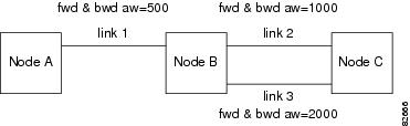
This section lists limitations for rteopt via parallel link. Use Figure 1 as you work through the scenarios in this section.
Figure 1 Configuration Example for rteopt via Parallel Link
The configuration for Figure 1 and the scenarios in this section are as follows:
•Link 1 has forward and backward admin weight set to 500 (via cnfpnni-intf).
•Link 2 has forward and backward admin weight set to 1000.
•Link 3 has forward and backward admin weight set to 2000.
•SPVC connection is routed from Node A to Node C (Master endpoint is at Node A) via link 1 and link 2.
Scenario 1: Link 2 is down (for example, by using the dnpnport command), connections are rerouted right away but Node A has not had that information updated in the routing tables yet.
SPVC on Node A will have routing cost = 2*500 + 2*1000 = 3000, but since link 2 is down, Node B will choose link 3. The routing cost on Node A SPVC is still 3000 as it did the calculation during the route search.
If link 2 is up, if you use a rteopt command on Node A to obtain the new route, and the new path selected has a cost of 3000.
Because SPVC has 3000, it does not reroute through link 2.
Scenario 2: Instead of link 2 being down, if there is a crankback on link 2, the same result stated above occurs.
Scenario 3 (for CBR and VBR): Link selection is set as maxavcr, maxcr, or random on Node B (by using the cnfpnni -selection command) If link 2 has less bandwidth than link 3, and the link selection criteria at Node B is set to maxavcr, Node A will still put the cost as 3000 with least aw calculation, but Node B will choose link 3 (even though it is costlier) because it has more bandwidth.
Scenario 4 (for ABR and UBR): Link selection does not apply to ABR and UBR (by using the cnfpnni -selection command). This is exactly the same as Scenario 3 because ABR and UBR follow load balancing on parallel links instead of choosing the minaw link.
Scenario 5 (for all types of service categories): After call setup, if the admin weight is increased on the link on which the call is routed, the routing cost calculated during the call setup will not get changed. So if a rteopt is done after increasing admin weights on the existing links on the connection path, the connections will not get optimized to take the newer path.
Workaround
If you use the dnpnport command on link 2 (connections will be routed via link 3), after using the uppnport command on link 2, then use the cnfpnni-intf command to change the existing administrative weight on link 2 to a lesser value, for example, 800 (from 1000).
When the optrte command is used at Node A, routing cost will be = 2*500 + 800(fwd) + 1000 (bwd) = 2800 for the new route of link 2.
Because all SPVC connections have 3000 as the routing cost, connections will be rerouted on link 2.
Important Notes
This section provides general notes that apply to this release, and covers some procedures that are not yet in the manuals.
•You must use the SCT files released with Version 2.1.80 (number 2 and 3, which were included in Version 2.0.13 are similar to number 2 and 3 for 2.1.80) for the Control VC feature. If you are using the MPLS feature, then you will need to change to SCT 4 or 5, which were released with Version 2.1.00.
•By default, 2000 cps and 543 cps will be reserved for SSCOP and PNNI Signalling VC respectively, even when you disable SSCOP and PNNI. These values are configurable by the cnfpnctlvc command.
•Do not execute the delcontroller command when connections/ports still exist. The impact of executing delcontroller with connections is that the connections cannot be recovered until the controller is re-added using addcontroller and the AXSM cards or the entire node has to be reset (otherwise ports remain in the provisioning state). There is now a warning to the user of the impact of the command when there are existing connections/ports.
•Analysis of the code has identified a situation which has a low probability of occurring and in fact has not been encountered in any test scenarios to date. This caution and associated workaround is provided as a precautionary measure. When the link bandwidth for SPVC connections is reaching full capacity, making minimal bandwidth available for new SPVC connections, a condition can be encountered where the initial software check believes there is sufficient bandwidth for the new SPVC connection. However, the final software confirmation for available bandwidth may be rejected because there is no bandwidth available. If this problem occurs, the system will recover when the PNNI updates are refreshed. (This will happen at the default time of 30 minutes.) The user can recover from this problem by making the Administrative weight of that link very high to avoid that link from being used.
•When the switch cannot automatically resolve nativity check conflicts, you can force a configuration rebuild from a specific hard disk by establishing a console port session through the corresponding PXM-UI-S3 card and issuing the shmRecoverIgRbldDisk command. This command ignores the nativity check and configures the entire switch according to the configuration on the hard disk.
•PNNI default minimum VCI is 35 unless changed explicitly. The reason for the default is to reserve VCI=32-34 for other control purposes (for example, MPLS and NCDP). For users who would like to add MPLS controller in future releases of MGX 8850, it is highly recommend to set the min-vci value to be 35 or more for all partitions on the port where the MPLS partition will be added. By doing so, the TDP sig vc for MPLS will be established automatically on 0/32. Minimum VPI is not negotiated by ILMI, so the user should set this parameter the same on both nodes.
APS Management Information
The following tips apply to the use of the dspapsbkplane command and the APS connector, which is sometimes called a backplane. The APS connector must be installed to enable intercard APS.
The APS dspapsln, dspapslns, switchapsln, and dspapsbkplane commands were modified in release 2.1.70.
Note The dspadjlnalm and dspadjlnalmcnt commands are new to Release 3.0.00. The dspadjlnalmcnt command is supported on AXSM/B.
The APS dspadjlnalm command was new to release 2.1.70. Refer to the Release Notes for MGX 8850 Command Reference for Release 2.1 at the following location for further details about the commands mentioned in these release notes:
http://www.cisco.com/univercd/cc/td/doc/product/wanbu/8850r21/index.htm
Note The issues in this section are seen only in Operational mode 1+1, bidirectional, Rev/non-Rev. If at least one side is configured as 1+1 unidirectional, these problems do not occur.
The following are some open issues in this release:
•Reset of active AXSM/A or AXSM/B, removal of active AXSM/A or AXSM/B, or AXSM/A or AXSM/B card switchover may cause the lines behind that card to be in an LOS status for 20ms to 30ms. If these lines were active at the time, some additional APS switch will occur; and the corresponding lines at the far-end will be in SF alarms before the standby AXSM card comes up. The momentary loss of signal is due to the hardware limitation; no other workaround is available. (Refer to caveat CSCdu41763—P-comment and CSCdv01058—Eng-Note for more details.)
Preparing for Intercard APS
The following components are required for intercard APS:
•Two front cards.
•Two back cards for every bay hosting APS lines. All lines on cards used for intercard APS must operate in APS pairs or use Y cables.
•An APS connector installed between the two back cards for every bay hosting APS lines.
Use the dspapsbkplane command on both the standby and active card to verify that the APS connector is plugged in properly. The following example shows the results displayed by the dspapsbkplane command when the APS connector is in place:
M8xx0_NY.1.AXSM.a > dspapsbkplaneLine-ID Primary Card Signal Status Secondary Card Signal StatusSlot #1 Slot #21.1 PRESENT PRESENT1.2 PRESENT ABSENT2.1 PRESENT ABSENT2.2 PRESENT ABSENTRemote Front Card : PRESENTTop Back Card : ENGAGEDBottom Back Card : ENGAGEDThe following example shows the results displayed by the dspapsbkplane command when the APS connector is not place:
M8xx0_LA.1.AXSM.a > dspapsbkplaneLine-ID Primary Card Signal Status Secondary Card Signal StatusSlot #1 Slot #21.1 PRESENT ABSENT1.2 ABSENT ABSENT2.1 PRESENT ABSENT2.2 ABSENT ABSENTRemote Front Card : ABSENTTop Back Card : ENGAGEDBottom Back Card : NOT-ENGAGED
Note The dspapsbkplane command should be used only when the standby card is in the Ready state. When the standby card is booting or fails, intercard APS cannot work properly and this command displays NOT ENGAGED.
If the dspapsbkplane command displays the APS Line Pair does not exist message, suspect that the APS is not configured on a line.
If the dspapsbkplane command shows different values for each of the two cards, suspect that the APS connector is seated properly on one card but not on the other.
The APS connector status is the same for all lines in a single bay because the APS connector interconnects two back cards within the same bay. You need to enter the dspapsbkplane command only once to display the APS connector status for both upper and lower bays.
Enter the dspapslns command to verify APS configuration. If the working and protection lines show OK, both lines are receiving signals from the remote note.
Managing Intercard APS Lines
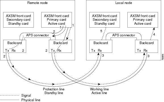
In AXSM/B intercard APS, either front card can be active, and can be connected to either APS line through the APS connector joining the two back cards. The following process describes how intercard APS communication works:
1. The signal leaves the front card at the remote end of the line. (See Figure 2 and Figure 3.)
2. The signal passes through the APS connector and both back card transmit ports at the remote end of the line. (See Figure 2 and Figure 3.)
3. The signal travels through both communication lines to the receive ports on both back cards at the local end. (See Figure 2 and Figure 3.)
4. The active front card processes the signal that is received on the active line. (See Figure 2 and Figure 3.)
5. The standby card monitors only the status of the standby line. (See Figure 2 and Figure 3.)
6. If necessary, the signal passes through the APS connector to the front card. (See Figure 3.)
Note For AXSM/B, the front card monitors both the receive lines.
Figure 2 shows an example of how this process operates in a standard APS configuration, where the primary card monitors the working line and the secondary card monitors the protection line.
Figure 2 Standard APS Configuration
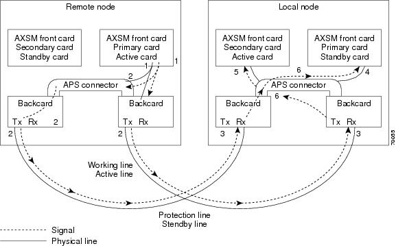
Figure 3 shows an example of how the APS communication process operates in a crossed APS configuration, where the secondary card monitors the working line that is attached to the primary card, and the primary card monitors the protection line that is connected to the secondary card.
Figure 3 Crossed APS Configuration
Line failures are always detected at the receive end of the line. This is where a switchover occurs when a failure is detected. Two different types of switchovers can occur, depending on whether the APS was configured as unidirectional or bidirectional in the cnfapsln command:
•When a failure occurs on a line configured for unidirectional switching, the switch changes lines at the receive end only. A switchover is not necessary at the transmit end because the transmitting back cards send signals on both lines in the 1 +1 APS configuration.
•When a failure occurs on a line configured for bidirectional switching, a switchover occurs at both ends of the line.
If the status of the standby line is good, a switchover from the failed active line to the standby is automatic.
Enter the cnfapsln command to enable an automatic switchover back to the working line after it recovers from a failure, as shown in the following example:
M8xx0_LA.1.AXSM.a > cnfapsln -w 1.1.1 -rv 2Table 7 describes the configurable parameters for the cnfapsln command.
If you want to manually switch from one line to another, enter the switchapsln <bay> <line> <switchOption> <service switch> command, as shown in the following example:
M8xx0_LA.1.AXSM.a > switchapsln 1 1 6Manual line switch from protection to working succeeded on line 1.1.1Table 8 describes the configurable parameters for the cnfapsln command.
Enter the dspapslns command to verify that the active line switched over from the protection line to the working line, as shown in the following example:
M8xx0_LA.1.AXSM.a > dspapslnsWorking Prot. Conf Oper Active WLine PLine WTR Revt Conf Oper LastUserIndex Index Arch Arch Line State State (min) Dir Dir SwitchReq------- ----- ---- ----- ------ ----- ----- ----- ---- ---- ---- ----------1.1.1 2.1.1 1+1 1+1 working OK OK 5 Yes bi bi ManualP->WTroubleshooting APS Lines
This section describes the port light behavior changed in Release 3.0.00 as follows:
•Port lights on AXSM /B front cards indicate the receive status of APS lines.
•The active front card always displays the status of the active line.
•The standby card always displays the status of the inactive line. If only one APS line fails, the line failure LED is always displayed on the standby front card.
•Port lights on AXSMB front cards indicate the receive status of the physical line connected to it. For example, when APS is configured for working line as 5.1.3 and protection line as 6.1.3, regardless of which card is active, the port LED on card 5 will show the receive status of 5.1.3 and card 6 will show the receive status of 6.1.3.
Note The remainder of this section is the same as for Release 2.1.80 unless otherwise noted as updated for Release 3.0.10.
Caution When the active front card and the active line are in different slots and the inactive line has failed, it is easy to incorrectly identify the failed line as the line in the standby slot. To avoid disrupting traffic through the active line, verify which physical line is at fault before disconnecting the suspect line.
If the active line fails and the standby line is not available, the switch reports a critical alarm.
If the active line fails and the standby line takes over, the former standby line becomes the new active line, and the switch reports a major alarm.
If an AXSM/A front card fails, APS communication between the redundant front cards fails. This can result in one of the following situations:
•If both APS lines were working before the failure, an APS line failure causes a switchover to the protection line.
•If either APS line failed prior to a front card failure, a failure on the active line does not cause a switchover to the other line. Because the standby front card failed, it cannot monitor the standby line and report when the line has recovered. This means that the active card cannot use the standby line until the standby front card is replaced and the line problem corrected.
Use the following procedure to troubleshoot APS lines:
Step 1 Enter the dsplns command to determine if the line in alarm is an APS line. The dsplns command shows which lines are enabled for APS:
M8xx0_LA.1.AXSM.a > dsplnsMedium MediumSonet Line Line Line Frame Line Line Alarm APSLine State Type Lpbk Scramble Coding Type State Enabled----- ----- ------------ ------ -------- ------ ------- ----- --------1.1 Up sonetSts12c NoLoop Enable Other ShortSMF Clear Enable1.2 Up sonetSts12c NoLoop Enable Other ShortSMF Clear Disable2.1 Up sonetSts12c NoLoop Enable Other ShortSMF Clear Disable2.2 Up sonetSts12c NoLoop Enable Other ShortSMF Clear DisableIf the line in alarm is an APS line, and has always functioned properly as an APS line, proceed to Step 2.
If the line in alarm has never functioned properly as an APS line, verify that the following are true:
•Redundant front and back cards are in the appropriate bays and are installed at both ends of the line.
•Cable is properly connected to both ends of the line.
•Enter the dspapsbkplane command to verify that the APS connector is installed properly at both ends of the line.
Step 2 Enter the dspapslns command at both ends of the communication line to determine whether one or both lines in an APS pair are bad. Use Table 9 to help you determine which APS line is not functioning properly.
Note Table 9 is updated for Release 3.0.00.
Table 9 Troubleshooting APS Line Problems Using the dspaps Command
Active Line Working Line Protection Line Working Line LED Protection Line LED DescriptionWorking
OK
OK
Green
Green
Active card is receiving a signal on working and protection lines. This does not guarantee that transmit lines are functioning properly. You must view the status on a remote switch.
Protection
SF
OK
Green for AXSM/A
Red for AXSM/A
Green for AXSM/B
Red
Active card is receiving a signal on the protection line. No signal is received on the working line.
Working
OK
SF
Green
Red
Active card is receiving a signal on the working line. No signal is received on the protection line.
Working
SF
SF
Red
Red
Active card is not receiving a signal from either line. The working line was the last line to work.
Protection
SF
SF
Red
Red
Active card is not receiving a signal from either line. The protection line was the last line to work.
Working
UNAVAIL
UNAVAIL
—
—
The card set is not complete. One or more cards have failed or been removed. See Table 10 to troubleshoot card errors.
If one or both lines appear to be bad, determine whether the working or protection line is in alarm. Troubleshoot and correct the standby line first. Replace the components along the signal path until the problem is resolved.
•If the dspapslns command at either end of the line indicates a front or back card problem, resolve that problem first. (See Table 10 to troubleshoot card problems).
•If the dspapslns command shows a signal failure on the standby line, replace that line.
•If the standby line is still down, replace the cards along the signal path.
Installing and Upgrading to Release 3.0.20
For upgrades, the term graceful means the process does not interrupt switch traffic or change the switch configuration.
The MGX 8950 switch can be upgraded to Release 3.0.20 from Release 2.1.80 or 3.0.10.
Note Starting with Release 3.0.10, CLI commands and shellconn commands can be used to burn the boot images.
Important Upgrade Notes
AXSM/B Cards Running APS
•On upgrading to 3.0.10 and higher, the cnfxbarmgmt command has to be issued in the following cases to enable the loadsharing and auto shutdown when it is not enabled by default during the upgrade:
–A nongraceful upgrade from 2.0.x to 3.0.10 and higher.
–Upgrading from 2.1.76 or later when load sharing or auto shutdown is manually disabled.
AXSM Cards in Op B Mode and APS Lines
•If the firmware is being upgraded using loadrev/runrev to Release 3.0.10 and higher from Release 3.0.00, the APS lines must be deleted prior to the upgrade if all of the following conditions are met (refer to caveat CSCdy09317).
–APS is operating in the Operating Mode B. This can be verified from the output of the dspcd command on the AXSM card.
–APS lines have been added and none of the APS lines are configured with ITU-T protocol (that is, Annex-B protocol).
•When upgrading from 2.1.80 to 3.0.10 and higher, check that the working and protection lines are free of any line failures prior to issuing the enableaxsmbaps command. Otherwise, the ports can go down. If this problem is encountered, take out the receive part of the line that doesn't have the alarm and re-insert it (refer to caveat CSCdz50925).
NNI Ports
•Signaling must be configured on NNI ports prior to upgrading to Release 3.0.00 and higher. Otherwise, for an NNI port with no signaling and ILMI enabled, after upgrading to Release 3.0.00 and higher, the PNNI link will go down.
Manual Clocking
•Manual clocking may latch twice when upgrading the PXM45 controller cards from Release 2.1.x to Release 3.0.00 and higher.
Installation and Upgrade Procedures
The procedures to upgrade to Release 3.0.10 appear in "Appendix A, Downloading and Installing Software Upgrades" in:
•Cisco MGX 8850 (PXM45) and MGX 8950 Software Configuration Guide, Release 3 (DOC-7814577=)
•Cisco MGX 8850 (PXM1E) and MGX 8830 Software Configuration Guide, Release 3 (DOC-7814248=)
Note For MGX-RPM-XF-512 upgrade information, refer to the Cisco MGX Route Processor Module (RPM-XF) Installation and Configuration Guide, Release 3.
You can order manuals (see the "Obtaining Documentation" section) or download them from the main Multiservice Switch Documentation site as follows:
Step 1 Go to http://www.cisco.com/univercd/cc/td/doc/product/wanbu/index.htm.
Step 2 Click on the link that matches your product name or configuration, for example:
•MGX 8950
Step 3 Click on Release 3.
Step 4 Click on the Software Configuration Guide or RPM Installation manual.
Caveats
This section provides information about caveats associated with Release 3.0.10 software.
MGX 8950 Caveats
Severity level 1, 2, and 3 caveats are organized in this section as follows:
•"MGX 8950 Open Caveats in Release 3.0.20"
•"Status of MGX 8950 Caveats Found in Previous Releases"
•"MGX 8950 Resolved Caveats in Release 3.0.20"
MGX 8950 Open Caveats in Release 3.0.20
Table 14 lists the Severity 1 open caveats for the MGX 8950 Release 3.0.20 software.
Table 15 lists the Severity 2 open caveats for the MGX 8950 Release 3.0.20 software.
Table 16 lists the Severity 3 open caveats for the MGX 8950 Release 3.0.20 software.
Status of MGX 8950 Caveats Found in Previous Releases
Table 17 describes the status of caveats found in previous releases of MGX 8950 Release 3.0.20 software.
MGX 8950 Resolved Caveats in Release 3.0.20
Table 18 lists the resolved caveats for the MGX 8950 Release 3.0.20 software.
Known Route Processor Module or MPLS Caveats
For information about caveats with the RPM-PR or RPM/B card, refer to Release Notes for Cisco MGX Route Processor Module (RPM/B and RPM-PR) for MGX Release 1.2.11 and MGX Release 3.
For information about caveats with the RPM-XF card, refer to Release Notes for Cisco MGX Route Processor Module (RPM-XF) for MGX 8850 (PXM45) Release 3.0.10.
MGX-RPM-XF-512 Caveats
The new MGX-RPM-XF-512 card supports MGX 8850 (PXM45), Release 3.0.10.
For information about caveats with the MGX-RPM-XF-512 card, refer to Release Notes for Cisco MGX Route Processor Module (RPM-XF) for Release 3.0.10 of MGX 8850 (PXM45).
Acronyms
Table 19 describes the acronyms used in this document.
Documentation
The documents listed in this section are for the releases that are compatible with Release 3.0.20.
Note The technical documentation that supports this release may include descriptions of features not implemented as of this printing.
Related Documentation
Table 20 lists the release notes that support platforms that are interoperable with release 3.0.20. Release notes are available online only.
Table 21 through Table 31 list the Cisco publications that support the previous major release of these interoperable platforms. The publications contain additional information related to the operation of this product and associated equipment in a Cisco WAN switching network.
Cisco WAN Manager Release 11
The product documentation for the Cisco WAN Manager (CWM) network management system for Release 11 is listed in Table 21.
Table 22 WAN CiscoView Release 3 Documentation
Title DescriptionWAN CiscoView Release 3 for the MGX 8220 Edge Concentrator, Release 5
DOC-7812768=
Provides instructions for using this network management software application that allows you to perform minor configuration and troubleshooting tasks for element management of the Cisco MGX 8220 Edge Concentrator.
WAN CiscoView Release 3 for the MGX 8850 Edge Switch, Release 1
DOC-7811242=
Provides instructions for using this network management software application that allows you to perform minor configuration and troubleshooting tasks for element management of the Cisco MGX 8850 Edge Switch.
WAN CiscoView Release 3 for the MGX 8250 Edge Concentrator, Release 1
DOC-7811241=
Provides instructions for using this network management software application that allows you to perform minor configuration and troubleshooting tasks for element management of the Cisco MGX 8250 Edge Concentrator.
WAN CiscoView Release 3 for the MGX 8230 Multiservice Gateway, Release 1
DOC-7810926=
Provides instructions for using this network management software application that allows you to perform minor configuration and troubleshooting tasks for element management of the Cisco MGX 8230 Multiservice Gateway.
WAN CiscoView for Release 2 of the MGX 8850
DOC-7810349=
Provides instructions for using this network management software application that allows you to perform minor configuration and troubleshooting tasks for element management of the Cisco MGX 8850 switch.
WAN CiscoView Release 3 for IGX 8400 Switches
DOC-78111243=
Provides instructions for using this network management software application that allows you to perform minor configuration and troubleshooting tasks for element management of the Cisco IGX 8400 switch.
WAN CiscoView Release 3 for BPX 8600 Switches
DOC-7811244=
Provides instructions for using this network management software application that allows you to perform minor configuration and troubleshooting tasks for element management of the Cisco BPX 8600 switch.
WAN CiscoView Release 3 for the BPX SES PNNI Controller
DOC-7812303=
Provides instructions for using this network management software application that allows you to perform minor configuration and troubleshooting tasks for element management of the Cisco BPX SES1 PNNI2 Controller.
1 SES = Service Expansion Shelf Private Network-to-Network Interface
2 PNNI = Private Network-to-Network Interface
Cisco MGX 8850 (PXM45) Multiservice Switch Release 3
The product documentation for installing and operating the Cisco MGX 8850 (PXM45) Multiservice Switch Release 3 is listed in Table 23.
Table 23 Cisco MGX 8850 (PXM45) Multiservice Switch Release 3 Documentation
Title DescriptionCisco MGX 8850 (PXM45 and PXM1E) Hardware Installation Guide, Release 3
DOC-7814250=
Describes how to install the Cisco MGX 8850 switch. This guide explains what the switch does and covers site preparation, grounding, safety, card installation, and cabling. The Cisco MGX 8850 switch uses either a PXM45 or a PXM1E controller card and provides support for both broadband and narrowband service modules.
Cisco MGX 8830, MGX 8850 (PXM45 and PXM1E), and MGX 8950 Command Reference, Release 3
DOC-7814789=
Describes the PXM commands that are available on the CLI1 of the Cisco MGX 8830, Cisco MGX 8850, and Cisco MGX 8950 switches.
Cisco MGX 8850 (PXM45) and MGX 8950 Software Configuration Guide, Release 3
DOC-7814788=
Describes how to configure the Cisco MGX 8850 (PXM45) and the Cisco MGX 8950 switches with a PXM45 controller to operate as ATM edge or core switches. This guide also provides some operation and maintenance procedures.
Cisco SNMP Reference for MGX 8850 (PXM45 and PXM1E), MGX 8950, and MGX 8830, Release 3
DOC-7814747=
Provides information on all supported MIB2 objects, support restrictions, and traps for AXSM, AXSM-E, SRME, FRSM12, PXM45, PXM1E, RPM-PR, and RPM-XF.
Cisco Frame Relay Software Configuration Guide and Command Reference for the MGX 8850 FRSM12 Card, Release 3
DOC-7810327=
Describes how to use the high-speed Frame Relay (FRSM-12-T3E3) commands that are available in the CLI of the Cisco MGX 8850 (PXM45) switch.
Cisco AXSM Software Configuration Guide and Command Reference for MGX 8850 (PXM45) and MGX 8950, Release 3
DOC-7814257=
This guide explains how to configure the AXSM cards for operation and contains a command reference that describes the AXSM commands in detail. The AXSM cards covered in this manual are the AXSM, AXSM/B, AXSM-E, and AXSM-32-T1E1-E.
Cisco MGX and SES PNNI Network Planning Guide
DOC-7813543=
Provides guidelines for planning a PNNI network that uses the Cisco MGX 8850 (PXM45 and PXM1E), Cisco MGX 8950, and the Cisco BPX 8600 switches. When connected to a PNNI network, each Cisco BPX 8600 Series Switch requires an SES3 for PNNI route processing.
Cisco MGX Route Processor Module (RPM-XF) Installation and Configuration Guide, Release 3
OL-2768-01 (online only)
Describes how to install and configure the Cisco MGX Route Processor Module (RPM-XF) in the Cisco MGX 8850 Release 3 switch. Also provides site preparation, troubleshooting, maintenance, cable and connector specifications, and basic Cisco IOS configuration information.
Cisco VISM Installation and Configuration Guide, Release 3.0
OL-2521-01 (online only)
Describes how to install and configure VISM4 in the Cisco MGX 8850 (PXM1), Cisco MGX 8250, and Cisco MGX 8230 switches. Also provides troubleshooting, maintenance, cable and connector specifications, and Cisco CLI command configuration information.
Regulatory Compliance and Safety Information for the Cisco MGX 8830, MGX 8850 (PXM45 and PXM1E), and MGX 8950 Switches
DOC-7814790=
Provides regulatory compliance, product warnings, and safety recommendations for the Cisco MGX 8830, Cisco MGX 8850 (PXM45 and PXM1E), and Cisco MGX 8950 switches.
1 CLI = command line interface
2 MIB = Management Information Base
3 SES = Service Expansion Shelf
4 VISM = Voice Interworking Service Module
Cisco MGX 8850 (PXM1E) Multiservice Switch Release 3
The product documentation for installing and operating the Cisco MGX 8850 (PXM1E) Multiservice Switch Release 3 is listed in Table 24.
Cisco MGX 8950 Multiservice Switch Release 3
The product documentation for installing and operating the Cisco MGX 8950 Multiservice Switch Release 3 is listed in Table 25.
SES PNNI Controller Release 3
The product documentation for installing and operating the Service Expansion Shelf (SES) Private Network-to-Network Interface (PNNI) Controller Release 3 is listed in Table 26.
Cisco MGX 8830 Multiservice Switch Release 3
The product documentation for installing and operating the Cisco MGX 8830 Multiservice Switch Release 3 is listed in Table 27.
Cisco WAN Switching Software Release 9.3
The product documentation for installing and operating the Cisco WAN Switching Software Release 9.3 is listed in Table 28.
Cisco MGX 8850 (PXM1) Edge Concentrator Switch Release 1
The product documentation for installing and operating the Cisco MGX 8850 (PXM1) Edge Concentrator Switch Release 1 is listed in Table 29.
Cisco MGX 8250 Edge Concentrator Switch Release 1
The documentation for installing and operating the Cisco MGX 8250 Edge Concentrator Switch Release 1 is listed in Table 30.
Cisco MGX 8230 Edge Concentrator Switch Release 1
The documentation for installing and operating the Cisco MGX 8230 Edge Concentrator Switch Release 1 is listed in Table 31.
Obtaining Documentation
These sections explain how to obtain documentation from Cisco Systems.
World Wide Web
You can access the most current Cisco documentation on the World Wide Web at this URL:
Translated documentation is available at this URL:
http://www.cisco.com/public/countries_languages.shtml
Documentation CD-ROM
Cisco documentation and additional literature are available in a Cisco Documentation CD-ROM package, which is shipped with your product. The Documentation CD-ROM is updated monthly and may be more current than printed documentation. The CD-ROM package is available as a single unit or through an annual subscription.
Ordering Documentation
You can order Cisco documentation in these ways:
•Registered Cisco.com users (Cisco direct customers) can order Cisco product documentation from the Networking Products MarketPlace:
http://www.cisco.com/cgi-bin/order/order_root.pl
•Registered Cisco.com users can order the Documentation CD-ROM through the online Subscription Store:
http://www.cisco.com/go/subscription
•Nonregistered Cisco.com users can order documentation through a local account representative by calling Cisco Systems Corporate Headquarters (California, U.S.A.) at 408 526-7208 or, elsewhere in North America, by calling 800 553-NETS (6387).
Documentation Feedback
You can submit comments electronically on Cisco.com. In the Cisco Documentation home page, click the Fax or Email option in the "Leave Feedback" section at the bottom of the page.
You can e-mail your comments to bug-doc@cisco.com.
You can submit your comments by mail by using the response card behind the front cover of your document or by writing to the following address:
Cisco Systems
Attn: Document Resource Connection
170 West Tasman Drive
San Jose, CA 95134-9883We appreciate your comments.
Obtaining Technical Assistance
Cisco provides Cisco.com as a starting point for all technical assistance. Customers and partners can obtain online documentation, troubleshooting tips, and sample configurations from online tools by using the Cisco Technical Assistance Center (TAC) Web Site. Cisco.com registered users have complete access to the technical support resources on the Cisco TAC Web Site.
Cisco.com
Cisco.com is the foundation of a suite of interactive, networked services that provides immediate, open access to Cisco information, networking solutions, services, programs, and resources at any time, from anywhere in the world.
Cisco.com is a highly integrated Internet application and a powerful, easy-to-use tool that provides a broad range of features and services to help you with these tasks:
•Streamline business processes and improve productivity
•Resolve technical issues with online support
•Download and test software packages
•Order Cisco learning materials and merchandise
•Register for online skill assessment, training, and certification programs
If you want to obtain customized information and service, you can self-register on Cisco.com. To access Cisco.com, go to this URL:
Technical Assistance Center
The Cisco Technical Assistance Center (TAC) is available to all customers who need technical assistance with a Cisco product, technology, or solution. Two levels of support are available: the Cisco TAC Web Site and the Cisco TAC Escalation Center.
Cisco TAC inquiries are categorized according to the urgency of the issue:
•Priority level 4 (P4)—You need information or assistance concerning Cisco product capabilities, product installation, or basic product configuration.
•Priority level 3 (P3)—Your network performance is degraded. Network functionality is noticeably impaired, but most business operations continue.
•Priority level 2 (P2)—Your production network is severely degraded, affecting significant aspects of business operations. No workaround is available.
•Priority level 1 (P1)—Your production network is down, and a critical impact to business operations will occur if service is not restored quickly. No workaround is available.
The Cisco TAC resource that you choose is based on the priority of the problem and the conditions of service contracts, when applicable.
Cisco TAC Web Site
You can use the Cisco TAC Web Site to resolve P3 and P4 issues yourself, saving both cost and time. The site provides around-the-clock access to online tools, knowledge bases, and software. To access the Cisco TAC Web Site, go to this URL:
All customers, partners, and resellers who have a valid Cisco service contract have complete access to the technical support resources on the Cisco TAC Web Site. The Cisco TAC Web Site requires a Cisco.com login ID and password. If you have a valid service contract but do not have a login ID or password, go to this URL to register:
http://www.cisco.com/register/
If you are a Cisco.com registered user, and you cannot resolve your technical issues by using the Cisco TAC Web Site, you can open a case online by using the TAC Case Open tool at this URL:
http://www.cisco.com/tac/caseopen
If you have Internet access, we recommend that you open P3 and P4 cases through the Cisco TAC Web Site.
Cisco TAC Escalation Center
The Cisco TAC Escalation Center addresses priority level 1 or priority level 2 issues. These classifications are assigned when severe network degradation significantly impacts business operations. When you contact the TAC Escalation Center with a P1 or P2 problem, a Cisco TAC engineer automatically opens a case.
To obtain a directory of toll-free Cisco TAC telephone numbers for your country, go to this URL:
http://www.cisco.com/warp/public/687/Directory/DirTAC.shtml
Before calling, please check with your network operations center to determine the level of Cisco support services to which your company is entitled: for example, SMARTnet, SMARTnet Onsite, or Network Supported Accounts (NSA). When you call the center, please have available your service agreement number and your product serial number.
Copyright © 2002, 2003 Cisco Systems, Inc.
All rights reserved..