Feedback
Table Of Contents
MGX 8230 Command Line Interface
ForeSight and standard ABR Coexistence Guidelines
Performance Parameters for Foresight and Standard ABR
MGX 8230 Command Line Interface
Introduction
The preferred tools for configuring, monitoring, and controlling the Cisco MGX 8230 switch are the CiscoView and Cisco WAN Manager applications for equipment management and connection management, respectively. (The Cisco WAN Manager application is the former Cisco StrataView Plus application with the equipment management removed.) The command line interface (CLI) also provides access to a Cisco MGX 8230 switch and is highly applicable during initial installation, troubleshooting, and any situation where low-level control is useful.
The Cisco MGX 8230 series commands in the tables that follow are divided by major functional group. Each table shows the complete name of the command and the cards for which the command is valid. For further reference, refer to the Installation and Configuration document for your specific switch type. The Cisco MGX 8230 Installation and Configuration document provides conceptual information about how the Cisco MGX 8230 switch can best implement network services in your network configuration. Examples of usage for the more common commands appear in the configuration chapters of this manual.
The command line prompt shows the name of the switch, the number of the switch (which is always "1"), the slot number and type for the current card, and whether the card is in the active ("a") or standby state ("s"). The following is an example of the command line prompt:
excel.1.6.AUSM.a >In this case, the current card is an active AUSM in slot 6, and the name of the node is "excel."
The list of commands for the common equipment cards PXM and SRM appear in Table 1-1. These commands are available when you log into the PXM. The Portable AutoRoute (PAR) commands appear in Table 1-1. Applicable service module commands become available when you switch to a card by executing the cc command. The list of service module commands appear in Table 1-3. Many commands apply to both the common equipment cards and the service modules.
The command line prompt shows the name of the switch, the number of the switch (which is always "1"), the slot number and type for the current card, and whether the card is in the active ("a") or standby state ("s"). The following is an example of the command line prompt:
excel.1.6.AUSM.a >In this case, the current card is an active AUSM in slot 6, and the name of the node is "excel."
The command notation and argument parameters follow standard programming convention: a space separates the command and each parameter; variables have an italicized typeface; required arguments appear within "<>" marks; optional parameters appear within square brackets ("[ ]"); and a vertical bar (|) represents the logical OR function.
Note
You must type all command arguments then press Return or Enter rather than enter one parameter at a time.
When you enter a command with no parameters, a usage message appears. This message shows syntax and ranges for the applicable command parameters.
List of Commands
The list of commands for the common equipment cards PXM and SRM appear in Table 1-1. These commands are available when you log into the PXM. The Portable AutoRoute (PAR) commands appear in Table 1-1. Applicable service module commands become available when you switch to a card by executing the cc command. The list of service module commands appear in Table 1-3. Many commands apply to both the common equipment cards and the service modules.
?
Help
Use the ? command to view all commands associated with the current card, and to view a list of commands associated with a truncated command entry.
Card(s) on Which This Command Executes
PXM, FRSM, AUSM, CESM
Syntax
? [command]
Syntax Description
Related Commands
Attributes
Example
View all commands associated with a partial command entry string.
raviraj.1.7.PXM.a > ? conAvailable commands------------------addconclrconcntclrconcntscnfcondcondbdelcondspcondspconcntdspconsshellConntstcontstconsegraviraj.1.7.PXM.a >Example
View all commands associated with the current card.
System response for the ? command is identical to that when executing the help command. See the examples in the help section beginning on page 515.
abort
Abort
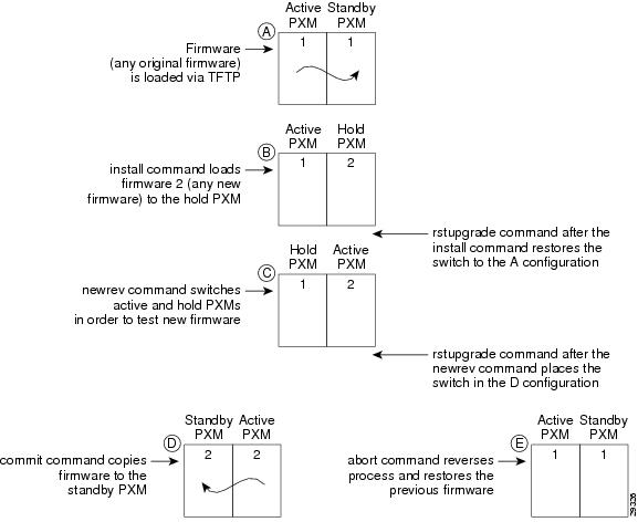
Use the abort command to stop the upgrade process and return to the previous firmware version.
•
•
Figure 1-1 illustrates the relationship of the abort command compared with other firmware commands.
Note
Figure 1-1 Firmware-Related Commands
Card(s) on Which This Command Executes
PXM
Syntax
abort <version>
Syntax Description
Related Commands
dspupgrade, rstupgrade, newrev, dspfwrevs, printrev, commit, copy, install
Attributes
Example
Abort loading firmware 1.1.10.
NODENAME.1.7.PXM.a > abort 1.1.10this may take a while ...abort command completed okThis card will be reset, the other will become active.Example
Errors loading firmware (multiple cases).
NODENAME.1.8.PXM.a > abort 1.1.11cannot be in 'upgrade idle', must be in 'upgrade' or 'upgradeinstall'ERR: command "abort" failedNODENAME.1.7.PXM.a > abort 1.1.111.1.11 is not the old version 1.1.10aaERR: command "abort" failedacqdsx3bert
Acquire DS3 BERT
Use the acqdsx3bert command to find out if a BERT session already exists on the selected
Cisco MGX 8230 switch bay.Card(s) on Which This Command Executes
FRSM 2CT3, CESMT3
Syntax
acqdsx3bert
Related Commands
cnfdsx3bert, dspdsx3bert, moddsx3bert, startdsx3bert, xcnfdsx3bert, xdspdsx3bert
Attributes
Example
Acquire the current BERT session.
NODENAME1.1.21.CESMT3.a > acqdsx3bertdspdsx3BertCntrs :BCRunning : 00BCStorage : 0BECRunning : 00BECStorage : 0DSX3 BERT in SyncNODENAME1.1.21.CESMT3.a >addapsln
Add APS Line
Use the addapsln command to set Automatic Protection Switching (APS) on a specified line for the current PXM.
APS is a SONET switching mechanism that routes traffic from working lines to protect them in case of a line card failure or fiber cut.
To set APS parameters, use the cnfapsln command following the addapsln command.
Card(s) on Which This Command Executes
PXM
Syntax
addapsln <workline> <workslot> <protectline> <protectslot> <archmode>
Syntax Description
Related Commands
cnfapsln, delapsln, dspapsln, switchapsln
Attributes
Example
Add APS Protection line 1 on slot 8 to APS Working line1 on slot 7. Set the APS architect mode on the working/protection line pair to 1+1.
spirit4.1.8.PXM.a > addapsln 1 7 1 8 2spirit4.1.8.PXM.a >addaimgrp
Add IMA Group
Use the addaimgrp command to set an AIMUX group on the current AUSM.
Card(s) on Which This Command Executes
AUSM
Syntax
addaimgrp <group_num> <port_type> <list_of_links> <minNumLinks>
Syntax Description
Related Commands
delaimgrp, cnfaimgrp, dspaimgrp, dspaimgrps
Attributes
Example
Add IMA group 2 as UNI with lines 3, 4, and 5.
Note
spirit4.1.18.PXM.a > addaimgrp 2 3.4.5spirit4.1.18.PXM.a >addcdrscprtn
Add Card Resource Partition
Use the addcdrscprtn command to set card-level resource partitions.
Note
The resource you can partition at the card level is the number of connections available to a network controller such as PAR.
With card-level partitioning:
•
•
Table 1-4 describes the effects of each of three usages of the addcdrscprtn command.
In addition to the definitions in Table 1-4, note the following characteristics of this command:
•
•
•
Card(s) on Which This Command Executes
PXM, FRSM, CESM, VISM
Syntax: PXM
addcdrscprtn <ctrlr_num> <num_glcns>
Syntax Description
ctrlr_num
Value to set controller type.
•
•
•
num_glcns
Number of available global logical connection numbers (GLCNs), in the range 0-32767.
Syntax: FRSM
addcdrscprtn <controller> <numOfLcnAvail>
Syntax Description
Syntax: CESM
addcdrscprtn <controller> <numOfLcnAvail>
Syntax Description
controller
Value to set controller type.
•
•
•
numOfLcnAvail
Maximum number of LCNs, in the range 0-248.
Related Commands
cnfcdrscprtn, dspcdrscprtn, delcdrscprtn
Attributes
Example
On current PXM, change the card-level partitioning to give 10000 GLCNs to PAR and 10000 GLCNs to Tag.
Note
spirit4.1.8.PXM.a > addcdrscprtn 10000 0 10000spirit4.1.8.PXM.a >addchan
Add Channel
Use the addchan command to configure channels on the current PXM, FRSM, AUSM, or CESM. The syntax for using addchan on an AUSM differs from that used on all other cards.
Card(s) on Which This Command Executes
PXM, FRSM (8T1/E1, HS1/B, VHS), AUSM, CESM
Syntax: PXM
addchan <LCN> <if_num> <conn_type> <vpi> <vci> <serv_type> <y_vpi> <y_vci> <y_nsap> <chan_master>
Syntax Description
Syntax: FRSM-8T1/E1
addchan <chan> <port> <dlci> <cir> <chan_type> [CAC] <mastership> <locnsap> <rmtvpi> <rmtvci> <rmtnsap>
Syntax Description
Syntax: FRSM-HS1/B
addchan <chan_num> <port_num> <dlci_num> <cir> <chan_type> [CAC] <mastership> <locnsap> <rmtvpi> <rmtvci> <rmtnsap>
Syntax Description
Syntax: FRSM-VHS
addchan <chan> <port> <dlci> <cir> <chan_type> <serv_type> [CAC_enable] <mastership> <locnsap> <rmtvpi> <rmtvci> <rmtnsap>
Syntax Description
Syntax: AUSM
addchan <channel number> <connection type> <port number> <vpi> <vci> <service type> <mastership> <locnsap> <rmtvpi> <rmtvci> <rmtnsap>
Syntax Description
Example
Add a VCC connection to channel 16 on port 1 with vpi=1, vci=1, ABR service type, and an egress queue number of 1.
spirit4.1.18.AUSM.a > addchan 16 2 1 1 1 3 1
spirit4.1.18.AUSM.a >
Syntax: CESM-8T1E1
addchan <chan_num> <port_num> <sig_type> <partial_fill> <cond_data> <cond_signal> [mastership | locnsap | rmtvpi | rmtvci | rmtnsap]
Syntax Description
Syntax: CESM-T3E3
addchan <chan_num> <port_num> <cond_sig> <mastership> <locnsap> <rmtvpi> <rmtvci> <rmtnsap>
Syntax Description
Related Commands
Attributes
addchanloop
Add a Channel Loopback
Use the addchanloop command to configure a channel loopback to the current FRSM or AUSM card. This command causes the channel to loop at the segmentation and reassembly (SAR) stage.
Card(s) on Which This Command Executes
FRSM, AUSM
Syntax: FRSM
addchanloop <chan_num>
Syntax Description
chan_num
Channel number to be used for the loopback on the current card.
•
–
–
–
–
Syntax: AUSM-8T1E1
addchanloop <port.VPI.VCI | ChanNum>
Syntax Description
Related Commands
Attributes
Example
Add channel loopback onto channel number 21.
s1.1.12.AUSMB8.a > addchanloop 21Example
Add channel loopback onto port 2, VPI 1, VCI 1.
s1.1.12.AUSMB8.a > addchanloop 2.1.1addcon
Add Connection
Use the addcon command to configure connectivity to the current card. The addcon command is preferable to addchan for adding a connection because addcon does not require the NSAP addresses.
Command execution includes a specification of the endpoint as either the master or the slave. Execute addcon first at the slave end, then the master end.
Note
Rather than a single number, SlaveConID is the node name, slot number, port number, and connection identifier (if applicable) of the slave end.
Service Types
In software Release 1.1.31, the service type options are expanded on the AUSM 8T1/E1, to include Standard ABR and real-time VBR connections, and for FRSM 8T1/E, all service types were added. Service types that are available via these modules are shown in Table 1-5.
ATM service categories support applications with distinct tolerances for delay, jitter, and cell loss, which in turn require control of bandwidth or throughput values. The ATM Forum has defined a family of service categories.
CBR and rt-VBR service types address the needs of applications that use precisely defined requirements for throughputs and delays. Applications that benefit from using these service categories include circuit emulation or entertainment-quality video.
VBR is treated in the software as non-real-time (nrt) VBR. This service type is intended for applications that have bursty traffic characteristics and do no have tight constraints on delay and delay variations. VBR service may support statistical multiplexing of connections.
UBR service type (the first service type developed for data) is intended for applications that have minimal service requirements, such as file transfers. UBR has no fairness of access mechanism; therefore, there is no way to specify higher priority connections.
ForeSight ABR (AUSM T1/E1) and fst ABR (FRSM T1/E1) are the Cisco-proprietary implementations of ABR. You can have both ForeSight ABR and Standard ABR connections on the same card. However, to migrate from ForeSight ABR connections to Standard ABR connections, you must physically delete the ForeSight ABR connection, then add the connection as Standard ABR using the addcon command.
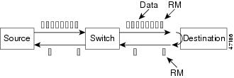
Standard ABR service type, based on TM 4.0, is useful for many applications. However, the main focus for development of Standard ABR is the economical support of data traffic. Data is segmented into ATM cells. The loss of any of the cells triggers the retransmission of the entire packet by a higher protocol layer. ABR service includes sharply defined objectives for cell loss, based on configured cell-loss ranges and feedback from the network to the traffic source. The ABR service guarantees a particular cell-loss ratio for all traffic offered in proper response to network feedback from Resource Management (RM) cells.
Depending on the values of Nrm, Trm, and Mrm (always 2), every Nrmth cell is an RM cell or every cell aftrer Trm (msecs) is an RM cell. Mrm comes into play at very low data rates. These RM cells travel to the destination and back, testing for congestion in the path. If a switch or destination is congested, it will mark a bit in the RM cell. The sender of the original packet receives the RM cell, interprets that there is congestion occurring somewhere, and slows down packets/cells to prevent cell loss. Once RM cells round-trip and return to the sender unmarked (without congestion notification) the sender increases traffic until, once again, marked RM cells are returned, signalling network congestion. Please refer to ATM Forum's TM 4.0 for details on Source, Destination, and Switch behaviors.
The following are the two implementations of Standard ABR:
•
•
Note
Figure 1-2 illustrates this process.1
Figure 1-2 ABR Source, Destination, and Switch Behavior
To configure Standard ABR on the FRSM-8T1/E1, use the following procedure:
1.
–
–
–
–
2.
–
–
3.
4.
5.
To configure Standard ABR on the AUSM 8T1/E1, use the following procedure:
1.
–
–
–
2.
The following information is about the default values:
–
–
–
–
3.
4.
5.
Upgrading to Standard ABR—AUSM-8T1/E1
1.
2.
3.
4.
5.
Upgrading to Standard ABR—FRSM-8T1/E1
1.
Note
ForeSight and standard ABR Coexistence Guidelines
In this release, Cisco has introduced the ability to support ABR TM4.0 as well as Foresight congestion control on the FRSM and AUSM modules. This section describes the major differences between the TM 4.0 compliant standard ABR and ForeSight. It also provides guidelines for the coexistence of ForeSight connections with standard ABR connections on the same network, with a worked example of how to configure the two different connection types to have similar characteristics
Foresight and ABR comparison
Foresight is similar to the rate-based ABR control system in TM 4.0, in that they both use Rate up and Rate down messages sent to the source of the connection to control the rate a connection runs at, based on congestion within the switches along that connection path. Both systems use Resource Management (RM) cells to pass these messages. The differences between the two systems that need to be considered are:
1.
ForeSight is a destination driven congestion notification mechanism. This means the destination switch is responsible for generating the RM cells, which defaults to every 100 ms. This means that any rate modifications at the source end happen approximately every 100 ms, and the time delay between the actual congestion at the destination and the source receiving information about the time delay could be 100ms.
In standard ABR, a source generates FRM cells every (nRM) cell intervals, where "n" is configurable. These are used to pass congestion information along to the destination switch, which then uses this information to generate BRM (Backward RM cells) back to the source.
A further consideration is that the actual user data flow will be lower for an equivalent rate due to the additional RM cells. Therefore, the more traffic being generated on a connection at any one time, the faster the feedback will be to the source.
There is also a TRM parameter which states that, if no RM cells have been generated after this time has passed, then one will automatically be sent.
Depending upon the speed at which it is running, an ABR connection may react faster or slower to congestion than the equivalent Foresight connection. For example, if an ABR connection runs at 100 cells per second, and nRM is 32, then approximately three RM cells will be generated per second, or once every 300 msecs. If it runs at 1000 cps then an RM cell would be generated approximately every 30 msecs. In both cases, the equivalent Foresight connection would generate an RM cell every 100 msec)
2.
In ForeSight, in response to a Rate Up cell from the destination, the source increases its rate by a percentage of the MIR for that connection. If we call this percentage the rate increase percentage (RIP), then RIP is configurable at the card level and by default it is 10%. In the case where MIR is low, the ForeSight rate increase will be slow as it has to increase as a percentage of MIR (rather than CIR).
On a standard ABR connection, in the event of available bandwidth (no congestion), the source increases its rate by a factor of (RIF*PCR). This means the rate increase step sizes are much bigger than for ForeSight for larger values of RIF (RIF has a range of 1/2, 1/4,....,1/32768). If RIF is not configured properly then standard ABR will ramp up its rate much faster and to a higher value. This is aided by the fact that the step sizes are bigger and the step frequency is higher in comparison with ForeSight.
3.
In ForeSight on receiving a Rate Down cell from the remote end, the source reduces its current rate (actual cell rate) by 13%. We will call this the rate decrease percentage (RDP). RDP is configurable at the card level.
In standard ABR, rate decrease is by an amount (RDF*ACR). Currently, the default value of RDF is 1/16 (i.e 6.25%). This means when this connection co-exists with ForeSight connections, in the event of congestion ForeSight connection reduces its rate by 13% whereas standard ABR connection reduces its rate by only 6.25%. Therefore, in the case of co-existence and approximating the same behavior across the two connection types, RDF should be changed to 1/8, so that both connections ramp down by the same amount, or 13%.
4.
In ForeSight, if the destination egress port drops any data due to congestion, then the destination sends a Fast Rate Down cell. Also, if a frame cannot be reassembled at the egress due to a lost cell somewhere in the network, a Fast-down is generated. On reception of Fast Rate Down the source reduces its current rate by 50% (this is again a card level configurable parameter).
Standard ABR does not distinguish between drops and the ECN/EFCI threshold being exceeded.
This means that, in case of drops in the egress port queue, a standard ABR connection rate reduces by only (RDF*ACR) but the ForeSight connection rate reduces by (ACR*0.5). Therefore, in the case of co-existence, if we need to approximate the same behavior across the two connection types then Fast down could effectively be disabled by configuring the reaction to be 13% rate down instead of 50%.
Guidelines
Both Foresight and Standard ABR systems work together within the network, but as the above description suggests, if the differences between the two systems are not taken into consideration, then a Foresight connection and an ABR connection with the same configuration parameters will not behave the same way within the network.
ABR and Foresight provide a mechanism for distributing excess bandwidth between connections over and above the minimum rate, therefore if these guidelines are not taken into consideration, the allocation of this excess bandwidth may be biased towards connections running one of these algorithms over connections running the other.
If this is a requirement, the following guidelines in Table 1-6 may be useful, assuming ForeSight is set to defaults except for Fast_Rate_down (which is set for 13%).
Example
Assume a network is currently running Foresight with default parameters, and supports the following four connection type, where CIR = MIR, PIR = port speed and QIR = PIR:
·T1 Port Speed = 64K CIR
Example: CIR = MIR = 64K
PIR = QIR = port speed = 1544
Fastdown = 13%
The following calculation used to convert between Frame based parameters (CIR, PIR, and so forth) and their equivalent cell-based parameters is FR_param *3/800. This allows for cell overheads based on frame sizes of 100 octets.)
CIR = MIR = (64000*3/800) = 240 cps
PIR = QIR = (1544 *3/800) = 5790 cps
Performance Parameters for Foresight and Standard ABR
AUSM-8 Performance
Table 1-8, Table 1-9, Table 1-10, Table 1-11, and Table 1-12 describe the performance that is measured for the E1 card. The "% of throughput" is % bandwidth of total line bandwidth.
Table 1-8 Foresight Connections
8
36000 cps/card, (15.9 Mbps),
99%
512
29268 cps/card, (12.66 Mbps),
82.8%
1000
28277 cps/card, (11.9 Mbps),
78%
Table 1-10 Switch Behaviour Standard ABR Connections. Connection Configuration Setting:
Nrm = 64, Trm = 100 msFull bandwidth supported.
FRSM-8 Performance
Table 1-12 FRSM-8 Performance: Connection Configuration Setting: Nrm = 64, TRM = 100 ms, Frame size = 100 bytes
64
12.6 Mbps
1000
7.1 Mbps),
Card(s) on Which This Command Executes
PXM, FRSM, CESM, AUSM
Syntax: PXM
addcon <port_no> <conn_type> <local_VPI> <local_VCI> <service> [CAC] [mastership] [remoteConnId]
Syntax Description
Syntax: AUSM-8T1/8E1
addcon <port number> <Channel VPI> <Channel VCI> <Connection Type> <Service Type> [Controller Type] [Mastership] [Remote End Connection Id]
Syntax Description
Example
Add a Standard ABR connection with default parameters.
pxmsjc.1.11.AUSMB8.a > addconSyntax : addcon "port_num vpi vci conn_type service_type [Controller_Type][mastership] [remoteConnId]"port number -- values ranging from 1-8Channel VPI -- Virtual Path Identifier: 0 - 255Channel VCI -- Virtual Channel Identifier: 0 - 65535 for VCC, * for VPCConnection Type -- Connection Type : 0 - VCC , non zero - LocalVP Id of the VPC (1 to 1000)Service Type -- Service Type: 1 - CBR, 2 - VBR, 3 - Standard ABR,4 - UBR, 5 - rt-VBR, 6 - ForeSight ABRController Type (Signalling) -- 1: PVC (PAR) - Default , 2: SPVC (PNNI)Mastership -- 1 for master, 2 for slave Default:SlaveRemote end Connection ID -- Format : NodeName.SlotNo.PortNo.ExternalConnIdpossible errors are :a) Illegal/Invalid parametersb) channel already existsc) port may not be upExample
Use the dspconstdabr command to view the standard ABR values. The following default values are taken by the Standard ABR parameters for a connection.
pxmsjc.1.11.AUSMB8.a > addcon 1 30 300 0 3 1 1 pxmsjc.11.1.20.200pxmsjc.1.11.AUSMB8.a > dspconstdabrMinimum Cell Rate : 10 Cells per secondPeak Cell Rate : 10 Cells per secondInitial Cell rate : 10 Cells per secondRate Increase Factor : 128Rate Decrease Factor : 16Nrm -- Inrate Cell Count : 64Trm -- Time limit for Frm : 255 millisecondsTransient Buffer Exposure : 16777215 CellsFixed Round Trip Time : 0 millisecondsACR Decrease Time Factor : 500 millisecondsCutoff Decrease Factor : 16ABRType : Switch behavior without VS/VDSyntax: FRSM-T1/E1
addcon <port number> <DLCI> <CIR> <channel type> [CAC] [controller type] [mastership] [RemoteEndConID] [service type]
Syntax Description
Syntax: FRSM-2CT3
addcon <port number> <DLCI> <CIR> <channel type> <egress service type> [Adm_cntrl] <controller_type> <mastership> <RemoteEndConID>
Syntax Description
Syntax: FRSM-2T3/2E3
addcon <port number> <DLCI> <CIR> <channel type> <egress service type> [Adm_cntrl] <controller_type> <mastership> <RemoteEndConID>
Syntax Description
Syntax: FRSM-HS2
addcon <port number> <DLCI> <CIR> <channel type> <egress service type> [Adm_cntrl] <controller_type> <mastership> <RemoteEndConID>
Syntax Description
Syntax: CESM 8T1/E1
addcon <port_num> <sig_type> <partial_fill> <cond_data> <cond_signalling> [controller_type] [mastership] [RemoteEndConID]
Syntax Description
Related Commands
Attributes
adddiagtest
Add diagnostic test
Use the adddiagtest command to add a test as part of the online diagnostics on ASC.
Card(s) on Which This Command Executes
PXM
Syntax
adddiagtest <testNumber> <testState>
Syntax Description
Related Commands
None
Example
Add a diagnostic test to the applicable test number and test state.
PXM.a > adddiagtest 1 3Test Number 1 ? "BRAM Checksum" added to Online DiagnosticsUse Unique Test ID 16 to refer to this test
addendpt
Add End Point
Use the addendpt command to set the endpoints on the VISM card. An endpoint is a logical port that consists of one or more DS0s. It resembles the logical port on the channelized FRSM or CESM card. The ds1_num and the ds0_list are used to create the endpoint ID. The SU requires the endpoint ID to send the Create Connection (CRCX) command of the SGCP protocol to the VISM.
Card(s) on Which This Command Executes
VISM
Syntax
addendpt <endpoint_num> <ds1_num> <ds0_list>
Syntax Description
Related Commands
None
Attributes
Example
Add endpoint number 1 to physical line 1. This endpoint uses DS0 1.
Note
spirit4.1.28.VISM.a > addendpt 1 1 1spirit4.1.28.VISM.a >addimagrp
Add IMA Group
Use the addimagrp command to configure an IMA group for the current AUSM.
Card(s) on Which This Command Executes
AUSM
Syntax
addimagrp <group_num> <port_type> <list_of_links>
Syntax Description
Related Commands
dspimagrp, dspimagrpcnt, dspimagrps, dspimainfo, dspimalncnt
Attributes
Example
Add IMA group 2 as UNI with lines 3, 4, and 5.
spirit4.1.88.AUSM.a > addimagrp 2 1 3.4.5
spirit4.1.88.AUSM.a >
addlink
Add Link
Use the addlink command to configure a link between a T1 line within a T3 line on an SRM-3T3 card and a slot and line number on a T1 service module.
Card(s) on Which This Command Executes
PXM
Syntax
addlink <T3LineNum> <T1Slot> <Number of T1s> <TargetSlotNum> <TargetSlotLineNum>
Syntax Description
Related Commands
Attributes
Example
Add a link between the T1 line 1 within T3 line 2 on the SRM-3T3 card in slot 15 and T1 line number 5 on the T1 service module in slot 3.
spirit4.1.8.PXM.a > addlink 15.2 1 3 5spirit4.1.8.PXM.a >addlmiloop
Add Loopback Line
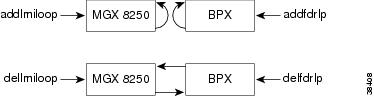
Use the addlmiloop command to stop sending LMI connection status messages to the BPX feeder trunk. This command should be used in conjunction with addfdrlp on the BPX. This command can be used only if a feeder trunk exists.
After you have executed the addlmiloop command on the Cisco MGX 8230 switch and the addfdrlp command on the BPX series switch, use the dsplmistats command on the BPX switch. The dsplmistats command shows the LMI messages exchanged between the BPX series switch and the Cisco MGX 8230 switch. The LMI messages will not show an increase after LMI looping is implemented.
Figure 1-3 illustrates the status messages halted between a Cisco MGX 8230 switch and a BPX switch.
Figure 1-3 Status Messages
Card(s) on Which This Command Executes
PXM
Syntax
addlmiloop <slot.port>
Syntax Description
Related Commands
Attributes
Example
Add an LMI loopback line numbered 1 to the current card (the PXM in slot 8).
spirit4.1.8.PXM.a > addlmiloop 1
spirit4.1.8.PXM.a >
Example
Add a feeder loop on the BPX.
spirit4.1.8.PXM.a > addfdrlp 5.5spirit4.1.8.PXM.a >Example
Display LMI loop.
spirit4.1.8.PXM.a > dsplmiloopTRK IN LMI LOOP-------------------1.8 YesExample
Display LMI statistics for the BPX. The number of LMI messages in the statistics does not increase.
VPI.VCI: 3.31 Lmi enabled Lmi polling enabledInvalid Pdu Rx: 0 Status Polling Timer (T396) : 10Invalid Pdu Len Rx: 14 Status Enquiry Timer (T393) : 10Unknown Pdu Type Rx: 0 Max Status Enquiry Retry (N394): 5Unknown IE Type Rx: 4 Update Status Timer (T394) : 10Bad Transaction Rx: 0 Max Update Status Retry (N395) : 5Status Rx: 46504 Spc Polling Timer : 2Status Enq Tx: 46546 Spc Retry Timer : 0Status Enq Rx: 92014 Spc Retry Counter : 1Status Tx: 92014 Node Status Retry Timer : 0Status Ack Rx: 185 Node Status Retry Counter : 0Update Status Tx: 297 Node Status Polling Timer : 8Update Status Rx: 203Status Ack Tx: 203VPI.VCI: 3.31 Lmi enabled Lmi polling enabledInvalid Pdu Rx: 0 Status Polling Timer (T396) : 10Invalid Pdu Len Rx: 14 Status Enquiry Timer (T393) : 10Unknown Pdu Type Rx: 0 Max Status Enquiry Retry (N394): 5Unknown IE Type Rx: 4 Update Status Timer (T394) : 10Bad Transaction Rx: 0 Max Update Status Retry (N395) : 5Status Rx: 46511 Spc Polling Timer : 0Status Enq Tx: 46553 Spc Retry Timer : 0Status Enq Rx: 92028 Spc Retry Counter : 1Status Tx: 92028 Node Status Retry Timer : 0Status Ack Rx: 185 Node Status Retry Counter : 0Update Status Tx: 297 Node Status Polling Timer : 9Update Status Rx: 203Status Ack Tx: 203addln
Add Line
Use the addln command to activate an OC-12, OC-3, T3, or E3 line on the current card.
Card(s) on Which This Command Executes
PXM, FRSM, AUSM, SRM-3T3, CESM, VISM
Syntax: PXM
addln -ds3 <LineNum> | -e3 <LineNum> | -sonet <LineNum>
Syntax Description
Note
port 1.
Syntax: FRSM (8T1, 2CT3, HS1/B), AUSM, SRM, CESM, VISM
addln <line_num>
Syntax Description
line_num
Line number, in the range appropriate for the interface.
•
•
•
Syntax: AUSM (8T1/E1, IMATM-T3T1/E3E1), SRM, CESM, VISM
addln <line_num>
Syntax Description
Related Commands
Attributes
Example
Add a line numbered 1 to current card (the PXM in slot 8).
spirit4.1.8.PXM.a > addln 1
spirit4.1.8.PXM.a >
addlnloop
Add Line Loop
Use the addlnloop command to set a specified line in loopback state on the current card.
Card(s) on Which This Command Executes
PXM, FRSM, AUSM, CESM
Syntax: PXM
addlnloop -ds3 <LineNum> | -e3 <LineNum> | -sonet <LineNum>
Syntax Description
Syntax: FRSM, AUSM, CESM
addlnloop <line_num>
Syntax Description
Related Commands
Attributes
addlns2aimgrp
Add Lines to an AIM Group
Use the addlns2aimgrp command to add lines to an existing AIMUX group.
Card(s) on Which This Command Executes
AUSM
Syntax
addlns2aimgrp <grp_num> <list_of_lines>
Syntax Description
Related Commands
Attributes
Example
Add lines 1 and 2 to IMA group 2.
spirit4.1.18.AUSM.a > addlns2aimgrp 2 1.spirit4.1.18.AUSM.a >addport
Add Port
Use the addport command to add a service port to the shelf's configuration.
Card(s) on Which This Command Executes
PXM, FRSM, CESM
Syntax: PXM OC-3
addport <port_number> <line_number> <percent_bandwidth> <min_vpi> <max_vpi>
Syntax Description
Syntax: PXM OC-12 back cards
addport <port_number> <line_number> <percent_bandwidth> <min_vpi> <max_vpi>
Syntax Description
Syntax: PXM T3/E3 back cards
addport <port_number> <line_number> <percent_bandwidth> <min_VPI> <max_VPI>
Syntax Description
Syntax: FRSM-8T1E1 and FRSM-8T1E1-C cards
addport <port_num> <line_num> <ds0_speed> <begin_slot> <num_slot> <port_type>
Syntax Description
Syntax: FRSM-2T3E3 cards
addport <port_num> <line_num> <port_type>
Syntax Description
Syntax: FRSM-2CT3
addport <port_num> <line_num> <ds0_speed> <begin_slot> <num_slot> <port_type>
Syntax Description
Syntax: FRSM-HS1/B
addport <port_num> <port_type>
Syntax Description
Syntax: FRSM-HS2
addport <port_num> <line_num> <ds0_speed> <begin_slot> <num_slot> <port_type>
Syntax Description
Syntax: CESM-8T1E1 cards
addport <port_num> <line_num> <begin_slot> <num_slot> <port_type>
Syntax Description
Syntax: CESM-T3E3 cards
addport <port_num> <line_num>
Syntax Description
Related Commands
cnfport, delport, dspport, dspports
Attributes
Example
Add port 1 on line 1 with DS0 timeslots 1 through 24 assigned as structured.
node501.1.1.CESM.a > addport 1 1 1 24 1node501.1.1.CESM.a >addred
Add Redundancy
Use the addred command to link two Cisco MGX 8230 switch slots (a primary slot and a secondary slot) so that the switch treats the cards in these slots as a redundant pair of cards.
The secondary slot should be in the same half of the shelf (upper or lower) as the primary slot. Redundancy can be 1:1 or 1:N. If the redundancy is 1:N, you must link one secondary slot to N primary slots through multiple executions of this command.
Card(s) on Which This Command Executes
PXM
Syntax
addred <redPrimarySlotNum> <redSecondarySlotNum> <redType>
Syntax Description
Related Commands
Attributes
Example
Add 1:1 redundancy between card in slot 4 and card in slot 1.
Note
node501.1.7.PXM.a > addred 1 4 1node501.1.7.PXM.a >addrscprtn
Add Resource Partition
Use the addrscprtn command to configure resource partitions for the current PXM.
A resource partition on a PXM consists of a percentage of bandwidth, a VPI/VCI range, and the number of global logical connection numbers (GLCNs) available to a network control application. The network control applications are Portable AutoRoute (PAR) and Tag switching. The configuration should reflect future development plans for PNNI or other controllers.
Note
Card(s) on Which This Command Executes
PXM
Syntax
addrscprtn <if_num> <ctrlr_num> <ingr_pct_bw> <egr_pct_bw> <min_vpi> <max_vpi> <min_vci> <max_vci> <max_chans>
Syntax Description
Related Commands
cnfrscprtn, delrscprtn, dspifrsc, dspifs, dsprscprtns, dsprscprtn, dsplnrsc
Attributes
addserialif
Add Serial Interface
Use the addserialif command to add a serial interface.
Card(s) on Which This Command Executes
PXM
Syntax
addserialif <serial_port_num>
Syntax Description
Related Commands
Attributes
Example
Configure speed on SLIP for 19200 bps.
NODENAME.1.7.PXM.a > addserialif 1NODENAME.1.7.PXM.a >addtrapmgr
Add Trap Manager
Use the addtrapmgr command to set up an SNMP trap manager for use with stand-alone applications. A trap manager registered (added) and reregistered through the SNMP interface by Cisco WAN Manager is deregistered (deleted) after 30 minutes if it is not reregistered. Trap managers that are added using the addtrapmgr command will not age, and will not be deleted after 30 minutes.
Card(s) on Which This Command Executes
PXM
Syntax
addtrapmgr <ip_addr> <portnum>
Syntax Description
Related Commands
deltrapmgr, dsptrapmgr, xcnftrapmgr
Attributes
Example
Add a trap manager with the IP address of 161.10.144.56 to port 162.
node501.1.7.PXM.a > addtrapmgr 161.10.144.56 162node501.1.7.PXM.a >addtrk
Add Trunk
Use the PAR addtrk command to activate a specified trunk on the current PXM.
The addtrk command applies only to routing node implementation. Execute addtrk after you have partitioned resources for PAR by using addrscprtn and configured the broadband interface as a trunk by using cnfifastrk.
Note
Card(s) on Which This Command Executes
PXM
Syntax
addtrk <slot.port>
Syntax Description
slot.port
Port identifier of the trunk to activate, using the format slot.port.
•
•
Related Commands
cnftrk, dsptrkcnf, dsptrkload, dsptrks
Attributes
Example
Activate trunk on port 4 in the card in slot 1.
node501.1.7.PXM.a > addtrk 1.4node501.1.7.PXM.a >adduser
Add User
Use the adduser command to configure a user name and associated access level on the PXM.
Card(s) on Which This Command Executes
PXM
Syntax
adduser <user_ ID> <accessLevel>
Syntax Description
Related Commands
Attributes
Example
Add a user named fin with privilege level ANYUSER.
spirit.1.7.PXM.a > adduser fin ANYUSEREnter password:Re-enter password:spirit.1.7.PXM.a >agetrapmgr
Age Trap Manager
Use the agetrapmgr command to activate or deactivate aging on trap managers.
Card(s) on Which This Command Executes
PXM
Syntax
agetrapmgr <ip_addr> <aging>
Syntax Description
Related Commands
Attributes
aimhelp
AIM Help
Use the aimhelp command to display the Help screen for the AUSM service module.
Card(s) on Which This Command Executes
AUSM
Syntax
aimhelp
Related Commands
Attributes
Example
Display Help screen for AUSM service module.
raviraj.1.9.AUSM8.a > aimhelpAUSM-8P Commandsaddcon : Add a Connectionaddimagrp : Add an IMA groupaddln : Add a lineaddlnloop : Configure a line in local loopbackaddlns2imagrp : Add lines to an existing IMA groupclralmcnt : Clear DS1 alarm countclralmcnts : Clear alarm count for all DS1 linesclralm : Clear the DS1 line alarmsclrchancnt : Clear Channel Countersclrchancnts : Clear Channel Counters for all channelsclralms : Clear DS1 alarms on all linesclrimagrpcnt : Clear IMA group Countersclrimalncnt : Clear IMA counters on a particular lineclrportcnt : Clear Port Countersclrportcnts : Clear Port Counters for all portsclrsarcnt : Clear SAR channel countersclrsarcnts : Clear SAR counters for all channelsclrslftst : Clear self test resultsclrimatst : clear IMA test procedureType <CR> to continue, Q<CR> to stop:cnfchanfst : Configure the channel foresight parameterscnfchanq : Configure the channel queue parameterscnffst : Configure foresight params of a cardcnfportq : Configure Egress queue parameterscnfimagrp : Configure an IMA groupcnfilmi : Configure ILMI parameters of a portcnfln : Configure DS1/E1 linecnflnloop : Configure DS1/E1 linecnfplpp : Configure DS1/E1 linecnfslftst : Configure self test parameterscnfsvcrange : Partition Resource between PVCs & SVCscnfupccbr : Configure UPC parameters of CBR connectioncnfupcvbr : Configure UPC parameters of VBR connectioncnfupcabr : Configure UPC parameters of ABR connectioncnfupcubr : Configure UPC parameters of UBR connectioncnfimatst : Enable the IMA test procedurecnfimaalmparm : Configure the IMA alaram Integration UP and DOWN timescopychans : Copy a template connectiondelimagrp : Delete an IMA groupType <CR> to continue, Q<CR> to stop:delcon : Delete a connectiondelln : Delete DS1 linedellnloop : Remove a DS1 line from local loopbackdellnsfmimagrp : Delete lines from an existing IMA groupdnport : Down an ATM portdspalm : Display DS1 alarms on a linedspalmcnf : Display DS1 alarm configurationdspalmcnt : Display alarm count for DS1 linedspalms : Display DS1 alarms on all linesdspcd : Display card informationdspchancnt : Display channel countersdspcon : Display connection configurationdspcons : Display all the configured connectionsdspfeature : Display the featuresdspfst : Display the card Foresight paramsdspilmi : Display ILMI parms of a portdspilmicnt : Display ILMI counters of a portdspimagrp : Display all parms configured for an IMA groupdspimagrpcnt : Display IMA group CountersType <CR> to continue, Q<CR> to stop:dspimagrps : Display the configured IMA groupsdspimalncnt : Display IMA counters on a particular linedspimatst : Display IMA test statusdspimaln : Display IMA link statusdspimaalmparm : Display IMA alarm integration timesdspln : Display DS1 linedsplns : Display all DS1 linesdsploads : Display the total bandwidth used up in each portdspplpp : Display the PLPP configuration of each linedspport : Display the configured ATM/IMA portdspportcnt : Display Port Countersdspportq : Display the egress queue configurationdspportqs : Display configuration of all egress queuesdspports : Display the configured ATM/IMA portsdspsarcnt : Display the SAR counters of a connectiondspsarcnts : Display the SAR counters of all connectionsdspslftst : Display self test configurationdspslftsttbl : Display the self test resultsdspsttatparms : Display the statistics params configuredType <CR> to continue, Q<CR> to stop:dspsvcrange : Display the resource partition between PVCs & SVCsdsptotals : Display the total connections configured per portrunslftstno : Run a particular self testtstcon : Test the connection towards the N/W sidetstconseg : Test the connection towards the CPE sidetstconsti : Test the connection towards the N/W side using STI supervisory celltstdelay : Measure the delay towards the N/W sidetstdelaysti : Measure the delay towards the N/W side using STI supervisory cellupport : Up an ATM portxcnfalm : Configure alms of a DS1 linexcnfln : Configure a DS1 linexcnfln : Configure a DS1 lineraviraj.1.9.AUSM8.a >arpAdd
Add Address Resolution Protocol Entry
Use the arpAdd command to add an Address Resolution Protocol (ARP) entry to the ARP table. This Internet protocol is used to map an IP address to a MAC address, and the ARP table contains these translations.
Card(s) on Which This Command Executes
PXM
Syntax
arpAdd <ip_address> <mac_address>
Syntax Description
ip_address
IP address in dotted decimal format.
mac_address
Standardized data link layer address, 6 bytes long. Also known as a hardware address, MAC-layer address, and physical address.
Related Commands
Attributes
Example
Add an ARP entry on current PXM and then show the ARP entry.
NODENAME.1.7.PXM.a > arpAdd 172.29.36.102 0:e0:4f:5c:6c:5aNODENAME.1.7.PXM.a > arpShow172.29.36.28 at 8:0:20:a6:80:3b190.29.36.255 at 0:e0:4f:5c:6c:20172.29.36.102 at 0:e0:4f:5c:6c:5a171.71.54.104 at 0:e0:4f:5c:6c:20NODENAME.1.7.PXM.a >arpDelete
Delete Address Resolution Protocol Entry
Use the arpDelete command to delete an entry in the Address Resolution Protocol (ARP) table. The ARP protocol is used to map an IP address to a MAC address, and the ARP table contains these translations.
Card(s) on Which This Command Executes
PXM
Syntax
arpDelete <ip_addr>
Syntax Description
Related Commands
Attributes
Example
Delete ARP entry for IP address 172.29.36.102.
NODENAME.1.7.PXM.a> arpDelete 172.29.36.102172.29.36.102 (172.29.36.102) deletedNODENAME.1.7.PXM.a>arpFlush
Flush Address Resolution Protocol Table
Use the arpFlush command to remove non-permanent entries from the ARP table. The ARP protocol is used to map an IP address to a MAC address, and the ARP table contains these translations.
Card(s) on Which This Command Executes
PXM
Syntax
arpFlush
Related Commands
Attributes
Example
Flush ARP table. Then, show ARP table.
NODENAME.1.7.PXM.a > arpFlushNODENAME.1.7.PXM.a > arpShow171.71.54.104 at 0:e0:4f:5c:6c:20NODENAME.1.7.PXM.a >arpShow
Show Address Resolution Protocol Table
Use the arpShow command to display the Address Resolution Protocol (ARP) table. The ARP table contains IP address-to-MAC address translations mapped by the ARP protocol.
Card(s) on Which This Command Executes
PXM
Syntax
arpShow
Related Commands
Attributes
Example
Show ARP table on current PXM.
NODENAME.1.7.PXM.a > arpShow190.29.36.255 at 0:e0:4f:5c:6c:20172.29.36.28 at 8:0:20:a6:80:3b171.71.54.104 at 0:e0:4f:5c:6c:20NODENAME.1.7.PXM.a >bootChange
Boot Change
Use the bootChange command to change to the boot IP address and gateway address of a PXM card. The IP address you define will be used only when the PXM is in boot state. Use the cnfifip command to assign IP addresses for the PXM and the shelf.
Note
The PXM tries to correct bad entries when it boots up. This information is copied to the standby card. If the bootChange IP address is different from the shelf IP address, then it will bring the Ethernet interface up on the standby with the bootChange IP address.
The shellconn version of this command updates only the local bootline values.
Note that several parameters are necessary for the network to function; specifically:
•
•
•
Note
If the CLI prompt is not there or if the switch is not enabled and in backup boot, you can use the usrEnetEnable command to bring up the Ethernet interface.
Card(s) on Which This Command Executes
PXM
Syntax
bootChange
Related Commands
Attributes
Example
Execute bootChange on current PXM.
raviraj.1.7.PXM.a > bootChange'.' = clear field; '-' = go to previous field; ^D = quitboot device : lnPciprocessor number : 0host name :file name :inet on ethernet (e) : 172.29.37.41 : ffffff00inet on backplane (b):host inet (h) :gateway inet (g) : 172.29.37.1user (u) :ftp password (pw) (blank = use rsh):flags (f) : 0x0target name (tn) :startup script (s) :other (o) :raviraj.1.7.PXM.a >bye
Bye
Use the bye command to exit the current CLI shell.
Card(s) on Which This Command Executes
PXM, FRSM, AUSM, VISM
Syntax
bye
Related Commands
Attributes
Example
Exit current CLI shell.
spirit.1.8.PXM.a > bye(session ended)cc
Change Card
Use the cc command to navigate from card to card on the shelf.
Card(s) on Which This Command Executes
PXM, FRSM, AUSM, CESM, VISM
Syntax
cc <slotNumber>
Syntax Description
Related Commands
None
Attributes
Example
Switch from AUSM in slot 22 to PXM in slot 8.
Note
node1.1.22.AUSM8.a > cc 8(session redirected)node1.1.8.PXM.a >cd
Change Directory
Use the cd command to change the current directory on the PXM hard disk.
Card(s) on Which This Command Executes
PXM
Syntax
cd <directory_name>
Syntax Description
Related Commands
ls, pwd, rename, deltree, copy
Attributes
Example
Change directory to FW.
raviraj.1.7.PXM.a > cd FWraviraj.1.7.PXM.a >Example
Verify the current directory by using the pwd command. Return to Root directory.
raviraj.1.7.PXM.a > pwdC:FWraviraj.1.7.PXM.a > cd ..raviraj.1.7.PXM.a > pwdC:raviraj.1.7.PXM.a >clraimgrpcnt
Clear AIM Group Counters
Use the clraimgrpcnt command to clear all the AIMUX-related counters for all lines in the specified AIMUX group.
Card(s) on Which This Command Executes
AUSM
Syntax
clraimgrpcnt <imagroup>
Syntax Description
imagroup
Number of the AIMUX group number on which you want to clear the AIMUX counters, in the range 1-8.
Related Commands
None
Attributes
Example
Clear all AIM group counters in AIM group 8.
node1.1.22.AUSM8.a > clraimgrpcnt 8node1.1.22.AUSM8.a >clraimlncnt
Clear AIM (or Clear IMA) Line Counters
Use the clraimlncnt command to clear all the AIMUX line counters for the specified IMA group.
Card(s) on Which This Command Executes
AUSM
Syntax
clraimlncnt (or clrimalncnt) <imagroup> <linenum>
Syntax Description
imagroup
Number of the AIMUX group on which you want to clear the line counters associated with an IMA group, in the range 1-8.
linenum
Line number, in the range 1-8.
Related Commands
Attributes
Example
Clear all AIM line counters in AIM group 8.
node1.1.22.AUSM8.a > clraimlncnt 8node1.1.22.AUSM8.a >clrallcnf
Clear All Configurations
Use the clrallcnf command to clear all configuration elements for all the cards in the node. The system will query for confirmation before executing the clrallcnf command.
Caution
Card(s) on Which This Command Executes
PXM
Syntax
clrallcnf
Related Commands
None
Attributes
Example
Clear configuration confirmation query.
node1.1.7.PXM.a > clrallcnfAll SM's config will be deleted, andthe shelf will be reset.Do you want to proceed (Yes/No)? No(command not executed)node1.1.7.PXM.a >clralldiagtests
Clear All Diagnostic Tests
Use the clralldiagtests command to delete all tests from online diagnostics that are currently configured. Confirmation of this command is seen by running the dspdiagtests command, which displays the following message:
No tests configured to run online
Card(s) on Which This Command Executes
PXM
Syntax
clralldiagtests
Related Commands
None
Example
Clear all the online diagnostic tests.
PXM.a > clralldiagtestsCleared all Online Diagnostic testsPXM.a > dspdiagtestsOnline Diagnostics : No tests configured to run onlinePXM.a >clralm
Clear Alarm
Use the clralm command to clear alarms on a specified line on the current card. Alarms occurring after this command executes are not affected. If alarms on a line are cleared with this command, the results may be observable through the dspalm command.
This command can clear alarms caused by the collection of statistical data only. Alarms caused by network failure cannot be cleared. For example, an alarm caused by a collection of bipolar errors can be cleared, but an alarm caused by a card failure cannot.
Card(s) on Which This Command Executes
PXM, FRSM, AUSM, CESM, VISM
Syntax: PXM
clralm -ds3 <LineNum> | -e3 <LineNum> | -sonet <LineNum> | -plcp <PLCPNUM>
Syntax Description
Syntax: FRSM, AUSM, CESM, or VISM
clralm -ds1 <LineNum>
Syntax Description
Syntax: SRM-3T3
clralm -srmds3 <LineNum>
Syntax Description
-srmds3
Command delineator that precedes the LineNum entry.
LineNum
LineNum = 1-N, where N = 3 if SRM-3T3
Syntax: FRSM-HS1
clralm -hs1 <LineNum>
Syntax Description
Related Commands
Attributes
Example
Clear all alarms caused by the collection of statistical data for line 1 on current card.
node1.1.22.AUSM8.a > clralm -ds1 1node1.1.22.AUSM8.a >clralmcnt
Clear Alarm Counters
Use the clralmcnt command to clear all the alarm counters and statistics on the specified line on the current card. All counters are reset to 0. The terminal does not display a response unless an error exists in the syntax.
Card(s) on Which This Command Executes
PXM, FRSM, AUSM, CESM, VISM
Syntax: PXM
clralmcnt -ds3 <LineNum> | -e3 <LineNum> | -sonet <LineNum> | -plcp <PLCPNUM>
Syntax Description
Syntax: FRSM, AUSM, CESM, or VISM
clralmcnt -ds1 <LineNum>
Syntax Description
-ds1
Command delineator that precedes the LineNum entry.
LineNum
Line number, in the range appropriate for the card.
•
•
•
Related Commands
Attributes
Example
Clear all alarm counters and statistics collected for line 1 on current card.
node1.1.22.AUSM8.a > clralmcnt -ds1 1node1.1.22.AUSM8.a >clralmcnts
Clear All Alarm Counters/Statistics on Current Card
Use the clralmcnts command to clear all the alarm counters and statistics on the current card. All counters are reset to 0. The terminal does not display a response unless an error exists in the syntax.
Card(s) on Which This Command Executes
FRSM, AUSM, CESM, VISM
Syntax
clralmcnts
Related Commands
Attributes
Example
Clear all alarm counters and statistics collected for current card.
node1.1.22.AUSM8.a > clralmcntsnode1.1.22.AUSM8.a >clralms
Clear Alarms on Card
Use the clralms command to clear alarms on the current card. Alarms occurring after this command executes are not affected.
This command can clear alarms caused by the collection of statistical data only. Alarms caused by network failure cannot be cleared. For example, an alarm caused by a collection of bipolar errors can be cleared, but an alarm caused by a card failure cannot.
Card(s) on Which This Command Executes
FRSM, AUSM, CESM, VISM
Syntax: FRSM, AUSM,CESM, or VISM
clralms -ds1 <LineNum>
Syntax Description
-ds1
Command delineator that precedes the LineNum entry.
LineNum
Line number on which to clear alarms, in the range 1-N, as appropriate for the physical installation.
Related Commands
Attributes
Example
Clear all alarms triggered by the collection of statistics for line 1 on current card.
node1.1.22.AUSM8.a > clralms -ds1 1node1.1.22.AUSM8.a >clratmlncnt
Clear All ATM Line Counters on Specified Line Number
Use the clratmlncnt command to clear the ATM event counters for the specified line on the PXM.
Card(s) on Which This Command Executes
PXM
Syntax
clratmlncnt <line_num>
Syntax Description
Related Commands
Attributes
Example
Clear all ATM event counters for line 1 on the PXM.
node1.1.7.PXM.a > clratmlncnt 1node1.1.7.PXM.a >clratmlncnts
Clear All ATM Line Counters on All Lines
Use the clratmlncnts command to remove all ATM counters on all the lines on the current card.
Card(s) on Which This Command Executes
PXM
Syntax
clratmlncnts
Related Commands
Attributes
Example
Clear all ATM event counters on the PXM.
node1.1.7.PXM.a > clratmlncntsnode1.1.7.PXM.a >clrbertcntrs
Clear BERT Counters
Use the clrbertcntrs command to remove all counters associated with bit error rate testing (BERT).
Card(s) on Which This Command Executes
FRSM 2CT3, CESMT3
Syntax
clrbertcntrs
Related Commands
acqdsx3bert, cnfdsx3bert, deldsx3bert, dspdsx3bert, startdsx3bert, xcnfdsx3bert, xdspdsx3bert
Attributes
Example
Clear all BERT counters on the current FRSM.
raviraj.1.13.VHS2CT3.a > clrbertcntrsraviraj.1.13.VHS2CT3.a >clrcderrs
Clear Hardware/Reset Errors in BRAM
Use the clrcderrs command to clear all card-related errors in a Cisco MGX 8230 series switch card. No response messages appear on screen. Refer to the dspcderrs description to see an example of the errors that this command clears, or execute the dspcderrs command before and after executing the clrcderrs command.
Card(s) on Which This Command Executes
PXM, FRSM, AUSM
Syntax
clrcderrs
Related Commands
Attributes
Example
Clear all card-related errors on the FRSM in slot 4.
node1.1.4.FRSM.a > clrcderrsnode1.1.4.FRSM.a >clrchancnt
Clear Channel Counters on Specified Channel
Use the clrchancnt command to clear the channel counters for the specified channel on the current card. Counting resumes after the command executes.
The following are the frame relay counters for each channel:
•
•
•
•
•
•
•
•
•
•
•
Card(s) on Which This Command Executes
PXM, FRSM, AUSM, CESM
Syntax: PXM
clrchancnt -cnt <chan_num> -cc <clrButton>
Syntax Description
Syntax: FRSM CESM
clrchancnt <chan_num>
Syntax Description
chan_num
Channel number, in the range appropriate for the card.
•
•
Syntax: AUSM
clrchancnt <Port.VPI.VCI | Chan_num>
Syntax Description
Port.VPI.VCI
Connection number, in the format port.VPI.VCI.
Chan_num
Channel number, in the range 16-1015.
Related Commands
dspchan, clrchancnts, dspchancnt
Attributes
Example
Clear all channel counters for channel 16 on the FRSM in slot 4.
node1.1.4.FRSM.a > clrchancnt 16node1.1.4.FRSM.a >clrchancnts
Clear All Channel Counters on Card
Use the clrchancnts command to clear all channel counters for all channels on the current service card. The counters resume accruing after the command executes. To view a list of the Frame Relay counters, see the clrchancnt command.
Card(s) on Which This Command Executes
PXM, FRSM, AUSM, CESM
Syntax
clrchancnts
Related Commands
dspchan,clrchancnt, dspchancnt
Attributes
Example
Clear all channel counters for all channels on the FRSM in slot 4.
node1.1.4.FRSM.a > clrchancntsnode1.1.4.FRSM.a >clrconcnt
Clear Connection Counters for Specified Connection Identifier
Use the clrconcnt command to clear the counters for the specified Connection Identifier on the current PXM card. Counting resumes after the command executes.
Card(s) on Which This Command Executes
PXM
Syntax
clrconcnt <conn_ID>
Syntax Description
Related Commands
Attributes
Example
Clear all counters for connection on port 1 with a VPI of 2 and a VCI of 2.
node4.1.8.PXM.a > clrconcnt 1.2.2node4.1.8.PXM.a >clrconcnts
Clear Connection Counters for All Connections on Card
Use the clrconcnts command to clear the counters for all the connections on the current PXM card. Counting resumes after the command executes.
Card(s) on Which This Command Executes
PXM
Syntax
clrconcnts
Related Commands
Attributes
Example
Clear all counters for all connections on the PXM card.
node4.1.8.PXM.a > clrconcntsnode4.1.8.PXM.a >clrdiagresults
Clear Diagnostic Results
Use the clrdiagresults command to clear the results of all the configured tests. To confirm that the results are cleared, you can run the dspdiagresults command.
Card(s) on Which This Command Executes
PXM
Syntax
clrdiagresults
Related Commands
None
Example
Display the diagnostic test results. Then, clear the test results.
PXM.a > dspdiagresultsID Test Name Result Pass Count Fail Count-- ------------------------------- --------- --------------- --------------1 BRAM Checksum PASS 5603 02 Trap Frequency Monitor FAIL 5602 13 Hard Disk Access PASS 5603 04 Framer Access PASS 5603 0PXM.a >clrdiagresultsPXM.a > dspdiagresultsID Test Name Result Pass Count Fail Count-- ------------------------------- --------- --------------- --------------1 BRAM Checksum N/A 0 02 Trap Frequency Monitor N/A 0 03 Hard Disk Access N/A 0 04 Framer Access N/A 0 0PXM.a >clrerr
Clear Error Log Counters for All Connections on Card
Use the clrerr command to remove specified or all error log files. This command queries for confirmation prior to clearing the error log files from the system.
Card(s) on Which This Command Executes
PXM
Syntax:
clrerr [-en <error slot>]
Syntax Description
-en
Command delineator that precedes the error slot entry.
error slot
Number of the log file to clear, which is identical to the slot number of the card.
Related Commands
Attributes
Example
Show the clrerr command confirmation query.
wilco.1.7.PXM.a > clrerrDo you want to proceed (Yes/No)? No(command not executed)wilco.1.7.PXM.a >clrifcnt
Clear Interface Counters for Specified Interface
Use the clrifcnt command to clear the counters for a specified broadband interface.
Card(s) on Which This Command Executes
PXM
Syntax
clrifcnt <if_num>
Syntax Description
Related Commands
Attributes
Example
Clear counters for the specified broadband interface (1).
wilco.1.7.PXM.a > clrifcnt 1ilco.1.7.PXM.a >clrifcnts
Clear All Interface Counters
Use the clrifcnts command to clear the counters for all the broadband interfaces.
Card(s) on Which This Command Executes
PXM
Syntax
clrifcnts
Related Commands
Attributes
Example
Clear counters for all broadband interfaces on the PXM card.
wilco.1.7.PXM.a > clrifcntswilco.1.7.PXM.a >clrimagrpcnt
Clear Inverse Multiplexing ATM Group Counters
Use the clrimagrpcnt command to clear Inverse Multiplexing ATM (IMA) group counters on the current AUSM card for a specified IMA group.
Card(s) on Which This Command Executes
AUSM
Syntax
clrimagrpcnt (or clraimgrpcnt) <imagroup>
Syntax Description
Related Commands
dspimagrp, dspimagrpcnt, dspimagrps, dspimainfo, dspimalncnt
Attributes
Example
Clear all inverse multiplexing ATM group counters for IMA group 1 on the AUSM card in slot 17.
flyers01.1.17.AUSM.a > clrimagrpcnt 1flyers01.1.17.AUSM.a >clrimalncnt
Clear AIM (or Clear IMA) Line Counters
Use the clrimalncnt command to clear all AIMUX line counters for a specified line in an IMA trunk.
Card(s) on Which This Command Executes
AUSM
Syntax
clrimalncnt (or clraimlncnt) <imagroup> <linenum>
Syntax Description
Related Commands
Attributes
Example
Clear all inverse multiplexing ATM line counters for IMA group 1 on the AUSM card in slot 17.
flyers01.1.17.AUSM.a > clrimalncnt 1flyers01.1.17.AUSM.a >clrlmistats
Clear All LMI Statistics
Use the clrlmistats command to clear the Local Management Interface (LMI)-related statistics on the current PXM.
Card(s) on Which This Command Executes
PXM
Syntax
clrlmistats
Related Commands
Attributes
Example
Clear LMI statistics on the PXM card.
penguin.1.7.PXM.a > clrlmistatsEnabled : 1 Port Status : 1VPI.VCI : 3.31Polling enable : 1T393 : 10 N394 : 5T394 : 10 N395 : 5WaitStatus : 0 WaitStAck : 0Retry Timer : 0 Retry Count : 1Poll Timer : 6 Trans Num : 86Status Rx : 0 Status Tx : 0UpdtStatus Rx : 0 UpdtStatus Tx : 0Status Enq Rx : 0 Status Enq Tx : 0Status Ack Rx : 0 Status Ack Tx : 0NodeStatus Rx : 0 NodeStatus Tx : 0NodeStaAck Rx : 0 NodeStaAck Tx : 0Bad PDU Rx : 0 Bad PDU Len Rx : 0Unknown PDU Rx : 0 Invalid I.E. Rx: 0Invalid Trans : 0BPX IP Addr : 172.3.3.62penguin.1.7.PXM.a >clrlog
Clear Log
Use the clrlog command to clear specified or all event log files. The log resumes accumulating event log messages after the command executes. This command queries for confirmation prior to removing all event log files.
Card(s) on Which This Command Executes
PXM
Syntax
clrlog [-log <log slot>]
Syntax Description
-log
Command delineator that precedes the log slot entry.
log slot
Number of the file that you want to clear from the event log file.
Related Commands
Attributes
Example
Clear all event log files on the PXM card.
wilco.1.7.PXM.a > clrlogDo you want to proceed (Yes/No)? Yeswilco.1.7.PXM.a >clrmsgcnt
Clear Control Message Counters
Use the clrmsgcnt command to clear the control message counters.
The following are the total number of control message counters:
•
•
•
•
•
•
•
This message also clears the control cell header received on the last unknown channel.
Card(s) on Which This Command Executes
PXM, FRSM, AUSM, CESM, VISM
Syntax
clrmsgcnt
Related Commands
Attributes
Example
Clear all control message counters on the AUSM card in slot 17.
flyers01.1.17.AUSM.a > clrmsgcnt 1flyers01.1.17.AUSM.a >clrportcnt
Clear Port Counters
Use the clrportcnt command to clear counter values on a specified port associated with the current PXM, AUSM, or FRSM.
Card(s) on Which This Command Executes
PXM, FRSM, AUSM
Syntax
clrportcnt <port_ number>
Syntax Description
port_ number
Port number, as appropriate for the current card.
•
•
•
–
–
–
•
•
Related Commands
Attributes
Example
Clear port counters on port 1 on the AUSM card in slot 17.
flyers01.1.17.AUSM.a > clrportcnt 1flyers01.1.17.AUSM.a >clrportcnts
Clear Port Counters
Use the clrportcnts command to clear all port counters on the current PXM, FRSM, or AUSM.
Card(s) on Which This Command Executes
PXM, FRSM, AUSM
Syntax
clrportcnts
Related Commands
Attributes
Example
Clear all port counters on all ports on the AUSM card in slot 17.
flyers01.1.17.AUSM.a > clrportcntsflyers01.1.17.AUSM.a >clrsarcnt
Clear SAR Counters
On an FRSM or CESM, use the clrsarcnt command to clear the segmentation and reassembly (SAR) counters for the particular channel in the argument. On an AUSM, use the clrsarcnt command to clear the SAR counters for the particular port.VPI.VCI connection.
The following are the SAR counters:
•
•
•
•
•
•
•
•
•
•
•
•
•
•
•
•
Card(s) on Which This Command Executes
FRSM, AUSM, CESM, VISM
Syntax: FRSM-8T1E1
clrsarcnt -chn <ChanNum>
Syntax Description
-chn
Command delineator that precedes the ChanNum entry.
ChanNum
Channel number in the range 16-1015.
Syntax: CESM-8T1E1
clrsarcnt -chn <ChanNum>
Syntax Description
-chan
Command delineator that precedes the ChanNum entry.
ChanNum
Channel number in the range 0-279.
Syntax: AUSM-8T1E1
clrsarcnt <port.VPI.VCI>
Syntax Description
port.VPI.VCI
Port range = 1-N, as appropriate for the physical installation.
VPI range = 1-4095.
VCI range = 1-65535.
Related Commands
Attributes
Example
Clear SAR counters for channel number 20 on the FRSM card.
NODENAME.1.17.FRSM.a > clrsarcnt -chn 20NODENAME.1.17.FRSM.a >clrsarcnts
Clear SAR Counters
Use the clrsarcnts command to clear the segmentation and reassembly (SAR) counters for all the channels or connections on the card from which the command is executed.
Syntax
clrsarcnts
Card(s) on Which This Command Executes
FRSM, AUSM, CESM, VISM
Related Commands
clrsarcnt, dspsarcnt, dspsarcnts
Attributes
Example
Clear all SAR counters on all cards in the node.
flyers01.1.17.AUSM.a > clrsarcntsflyers01.1.17.AUSM.a >clrscrn
Clear Terminal Screen
Use the clrscrn command to clear the control terminal screen. After this command executes, only the current command line prompt appears on the screen.
Card(s) on Which This Command Executes
PXM, FRSM, AUSM, CESM, VISM
Syntax
clrscrn
Related Commands
None
Attributes
Example
Clear the screen.
flyers01.1.17.AUSM.a > clrscrnflyers01.1.17.AUSM.a >clrslftst
Clear Self-Test
Use the clrslftst command to clear the results of the last self-test on the current card.
Card(s) on Which This Command Executes
FRSM, AUSM, CESM
Syntax
clrslftst
Related Commands
cnfslftst, dspslftst, runslftstno
Attributes
Example
Clear results of last self-test for the AUSM card in slot 17.
flyers01.1.17.AUSM.a > clrslftstflyers01.1.17.AUSM.a >clrsmcnf
Clear Service Module Configuration
Use the clrsmcnf command to clear the following configuration elements for the selected service card:
•
•
•
•
Note
Card(s) on Which This Command Executes
PXM
Syntax
clrsmcnf <slot num>
Syntax Description
Related Commands
Attributes
Example
Clear all configuration elements on the AUSM card in slot 17.
flyers01.1.7.PXM.a > clrsmcnf 17flyers01.1.7.PXM.a >clrsrmcnf
Clear SRM-3T3 Configuration
Use the clrsrmcnf command to clear SRM-3T3 card information and to remove all T1 link mappings. All links are switched back to their respective service modules.
Card(s) on Which This Command Executes
PXM
Syntax
clrsrmcnf <slot num>
Syntax Description
slot num
Slot number. Enter the value 15 or 31.
•
•
Related Commands
addlink, dsplink, xcnfsrmlink, xdspsrmlink
Attributes
Example
Clear all configuration information and remove all T1 link mappings on the SRM-3T3 card in slot 15.
flyers01.1.7.PXM.a > clrsrmcnf 15flyers01.1.7.PXM.a >cmdhistory
Display Command History
Use the cmdhistory command to view the last 10 commands executed on the current card.
Card(s) on Which This Command Executes
PXM
Syntax
cmdhistory
Related Commands
Attributes
Example
Display previous 10 commands executed on the PXM card.
spirit4.1.8.PXM.a > cmdhistorySize of cmdHistory is currently 10 line(s)1 dspconcnt 2.39.452 dsplmistats3 dsplmiloop4 dsplm5 clrportcnt6 dspportcnts7 dspportcnt8 dspportcnt 19 dsplmistats10 cmdhistoryspirit4.1.8.PXM.a >cnfaimgrp
Configure AIM Group
Use the cnfaimgrp command to configure an AIMUX group on the AUSM.
Card(s) on Which This Command Executes
AUSM
Syntax
cnfaimgrp <grp> <max_diff_delay> <min_num_links>
Syntax Description
Related Commands
addaimgrp, delaimgrp, dspaimgrp, dspaimgrps
Attributes
Note
The <read_wr_ptr_diff> value cannot be decreased from its existing value—it can only be increased (this is because decreasing the <read_wr_ptr_diff> in an established AIMUX group involves dropping cells that are stored in the delay compensation buffer.
Example
Configure AIMUX group 1 on the AUSM card in slot 17 to have a read/write pointer differential of 5, a link loss severity of 2, a maximum tolerable differential delay of 5, and two redundant links.
flyers01.1.17.AUSM.a > cnfaimgrp 1 -rwdiff 5 -severity 2 -maxdiff 3 -red 2flyers01.1.17.AUSM.a >cnfapsln
Configure APS Line
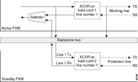
Use the cnfapsln command to set Automatic Protection Switching (APS) parameters for a line on the current PXM. APS is a standard that provides a means for SONET line redundancy. APS involves switching between working (active) and protection (standby) SONET lines in the event of a hardware failure detected by the receiving end or by the far end. This support applies only to PXM OC-3 and PXM OC-12 back cards.
The 1.1.20 software release provides support for the SONET Linear APS 1+1 mode with two back cards. The SONET Linear APS 1+1 standard specifies that for every working line there must exist a redundant protection line. Traffic protected by the redundant line is carried simultaneously on both the working line and the protection line. The line switch-over to the protection line has to be completed within 60 ms.
Figure 1-4 illustrates a "dual back card" redundancy configuration. This design requires two PXM front cards and two SONET back cards. Ports are paired as follows:
•
Figure 1-4 SONET APS 1+1 with Two Back Cards
SONET 155 also can be configured to have this redundancy configuration. Ports are paired as follows:
•
•
•
•
Switching of the paired port on the pair back card can be done independently of the other paired ports.
You must add an APS line with the addapsln command before using the cnfapsln command.
Card(s) on Which This Command Executes
PXM
Syntax
cnfapsln <workline> <SFBER> <SDBER> <WTR> <Direction> <Revertive> <K1K2>
Syntax Description
Related Commands
addapsln, delapsln, dspapsln, dspapscfg
Attributes
Example
Configure APS working line 1 on the active PXM card in slot 7 to have a signal failure BER threshold of 10^^5, a signal degrade BER threshold of 10^^5, to enable switch back after signal failure or degradation has cleared, to wait 2 minutes before attempting to switch back, to make switching bidirectional, and to enable the K1/K2 inband interface on the protection line.
flyers01.1.7.PXM.a > cnfapsln 1 5 5 1 2 1 1flyers01.1.7.PXM.a >cnfatmln
Configure ATM Line
Use the cnfatmln command to configure a UNI or NNI cell header for a PXM trunk. UNI cell headers are typically used on the line that connects to a workstation rather than a switch.
Note
Card(s) on Which This Command Executes
PXM (in a Cisco MGX 8230 switch stand-alone node)
Syntax
cnfatmln <line_num> <type>
Syntax Description
line_num
OC-3 or OC-12 line number, in the range appropriate for the interface.
•
•
type
Cell header type for either UNI or NNI.
•
•
Related Commands
Attributes
Example
Set cell header type for trunk 1 on the PXM to NNI.
flyers01.1.7.PXM.a > cnfatmln 1 3flyers01.1.7.PXM.a >cnfbctype
Configure Back Card Type
Use the cnfbctype command to specify the interface of the 12in1 dual-personality back card. The back card can be configured with either an X.21 or a V.35 interface. The default interface is V.35.
Note
Card(s) on Which This Command Executes
FRSM-HS1B
Syntax
cnfbctype <cardType>
Syntax Description
Related Commands
Attributes
Example
Configure the interface type on the current FRSM card.
man.1.14.FRSM.a > cnfbctype 1Example
Display the interface type on the current FRSM card.
man.1.14.FRSM.a > dspbctypeBackcard Personality: X.21cnfbert
Configure BERT
Use the cnfbert command to configure bit error rate testing (BERT) parameters on the PXM.
A BERT session does not time out automatically. Use the delbert command to end the test.
Caution
Card(s) on Which This Command Executes
PXM
Syntax: PXM
cnfbert <slot>
Syntax Description
Related Commands
delbert, dspbert, modbert, xcnfbert
Attributes
cnfcbclk
Configure Cell Bus Clock
Use the cnfcbclk command to set the cell bus (CB) operating clock rate to high (42 MHz) or low
(21 MHz). There are eight cell buses in a Cisco MGX 8230 switch shelf. You can use the cnfcbclk command to set the cell bus to different operating clock rates to take advantage of high-speed service modules whenever possible. Note that not all service modules can support the high clock rate.
Note
Card(s) on Which This Command Executes
FRSM_2CT3, FRSM_2T3, FRSM_2E3, FRSM_HS2, CESM_T3, CESM_E3, VISM_8T1, VISM_8E1, RPM (new), PXM
Syntax
cnfcbclk <cellBus> <clockRate>
Syntax Description
Possible Errors
The following are the possible errors:
•
•
Related Commands
Attributes
Example
Display the cards in the chassis.
NODENAME12.1.7.PXM.a > dspcdsCommand Executed :dspcdsSlot CardState CardType CardAlarm Redundancy---- ----------- -------- --------- -----------1.1 Empty Clear1.2 Active FRSM-8T1 Clear1.3 Empty Clear1.4 Empty Clear1.5 Empty Clear1.6 Active FRSM-8T1 Clear1.7 Active PXM1-OC3 Clear1.8 Empty Clear1.9 Empty Clear1.10 Empty Clear1.11 Empty Clear1.12 Empty Clear1.13 Empty Clear1.14 Empty Clear1.15 Empty Clear1.16 Empty Clear1.17 Empty Clear1.18 Empty Clear1.19 Empty ClearType <CR> to continue, Q<CR> to stop: qExample
Display the current clock settings.
NODENAME12.1.7.PXM.a > dspcbclkCommand Executed :dspcbclkCellBus Rate (MHz) Slot-------------------------------CB1 21 1, 2CB2 21 3, 4CB3 21 5, 6CB4 21 17 - 22CB5 21 9, 10CB6 21 11, 12CB7 21 13, 14CB8 21 25 - 30Example
Configure CB2 for 42 MHz.
NODENAME12.1.7.PXM.a > cnfcbclk cb2 42Command Executed :cnfcbclkExample
Display the clock settings with new setting for CB2.
NODENAME12.1.7.PXM.a > dspcbclkCommand Executed :dspcbclkCellBus Rate (MHz) Slot-------------------------------CB1 21 1, 2CB2 42 3, 4CB3 21 5, 6CB4 21 17 - 22CB5 21 9, 10CB6 21 11, 12CB7 21 13, 14CB8 21 25 - 30Example
Display the error messages when executing this command.
popeye12.1.7.PXM.a > cnfcbclk cb1 42Command Executed :cnfcbclkSet failed due to illegal option value(s)Syntax: cnfcbclk <cellBus> <clockRate>cellBus -- a string CB1..CB8clockRate -- a number 21 or 42 (MHz)WARNING: Certain Service Modules will not operate at the clock rate youspecified. Please check the Service Modules in the slots where the Cell Bus clockrate is effected by this commandcnfcdprtntype
Configure Card Partition Type
Use the cnfcdprtntype command to configure the type of partition to serve as the basis for sharing global logical connection numbers (GLCNs). The GLCNs are shared by the network controller applications (PAR, for example) on a logical broadband interface.
Card(s) on Which This Command Executes
PXM, FRSM, AUSM, CESM
Syntax
cnfcdprtntype <prtn_type>
Syntax Description
Related Commands
Attributes
Example
Allow all controllers access to all (G)LCNs available for the card.
spirit3.1.10.AUSMB8.a > cnfcdprtntype 1spirit3.1.10.AUSMB8.a >cnfcdrscprtn
Configure Card Resource Partition
Use the cnfcdrscprtn command to modify card-level resource partitions on the current card. This command creates a template of available connections among the network controllers to provide card-level partitioning for PAR, PNNI, or Tag. With card-level partitioning, the following can happen:
•
•
The matrix in Table 1-13 describes the effects of each of the three usages of the cnfcdrscprtn command.
Note
Additional characteristics of this command are:
•
•
Card(s) on Which This Command Executes
PXM, FRSM, AUSM, CESM, VISM
Syntax
cnfcdrscprtn <number_PAR_conns> <number_PNNI_conns> <number_Tag_conns>
Syntax Description
Related Commands
addcdrscprtn, delcdrscprtn, dspcdrscprtn
Attributes
Example
On current PXM, change card-level partitioning to give 10000 GLCNs to PAR and 10000 GLCNs to Tag.
Note
spirit.1.7.PXM.a > cnfcdrscprtn 10000 0 10000spirit.1.7.PXM.a >cnfchan
Configure Channel
Use the cnfchan command to configure channels on the current service card.
Card(s) on Which the Command Executes
PXM, AUSM, CESM
Syntax: PXM
cnfchan <LCN> <chan_rte_pri> <chan_max_cost> <chan_restrict_trk_type>
Syntax Description
Syntax: AUSM-8T1E1
cnfchan <chan_num> <RoutingPriority> <MaxCost> <RestrictTrunkType> <PCR> <MCR> <PctUtil>
Syntax Description
Syntax: CESM-8T1E1
cnfchan <chan_num> <CDVT> <CLIP> <bufsize> <clockmode> <IdleSuppEnable> <ForceIS>
Syntax Description
Syntax: CESM-T3E3
cnfchan <chan_num> <CDVT> <CLIP> <bufsize>
Syntax Description
Related Commands
Attributes
Example
On current AUSM in slot 17, change the configuration for channel 16 to set a routing priority of 1, a maximum cost of 5, restrict trunk routing for this channel to terrestrial trunks only, set the peak cell rate to 655525 cells per second, set the minimum cell rate to 655525 cells per second, and set the percent utilization to 100 percent.
spirit.1.17.AUSM.a > cnfchan 16 1 5 2 65525 65525 100spirit.1.17.AUSM.a >cnfchanabrparams
Configure Channel Standard ABR Parameters
Use the cnfchanabrparams command to configure ABR parameters for channels on an FRSM-8T1/E1 service module.
To configure rate parameters, see thecnfconstdabr command.
For more information about configuring Standard ABR, including default ABR parameters, see the addcon command.
Card(s) on Which This Command Executes
FRSM-8T1/E
Syntax
cnfchanabrparams <Port.DLCI/CHAN_NUM> <rif > <rdf> <nrm> <trm> <tbe> <frtt> <adtf> <cdf>
Syntax Description
Related Commands
cnfchanabrrates, dspchanstdabr, cnfchanstdabr, addcon, dspchan
Attributes
Example
Display the parameters for the cnfchanabrparams command.
NODENAME.1.29.FRSM.a > cnfchanabrparamsSyntax : cnfchanabrparams "Port.DLCI/CHAN_NUM rif rdf nrm trm tbe frtt adtfcdf"Port.Dlci -- Port.Dlci identifying a connectionRIF -- Valid values range from 1 to 32768 (in steps of power of 2)RDF -- Valid values range from 1 to 32768 (in steps of power of 2)Nrm -- Valid values range from 2 to 256 (in steps of power of 2)Trm -- Valid values range from 3 to 255 in msec.TBE -- Valid values range from 0 to 16777215 in cellsFRTT -- Valid values range from 0 to 16700 in msec.ADTF -- Valid values range from 10 to 10230 in msec.CDF -- Valid values range from 0 to 64 (in steps of power of 2)<Get an example>cnfchanabrrates
Configure Channel ABR Rates
Use the cnfchanabrrates command to configure the rate parameters of the Standard ABR channel.
Card(s) on Which This Command Executes
FRSM-8T1E1
Syntax
cnfchanabrrates <Port.DLCI/Channel Number> <MCR> <PCR> <ICR>
Syntax Description
Related Commands
cnfchanstdabr, dspchanstdabr, cnfchanabrparams, addcon, dspchan
Attributes
Example
Display the parameters for the cnfchanabrrates command.
NODENAME.1.29.FRSM.a > cnfchanabrratesSyntax : cnfchanabrrates "Port.DLCI/CHAN_NUM mcr pcr icr "Port.Dlci -- Port.Dlci identifying a connectionMCR -- Valid values range from 10 to 10000 in cells/secPCR -- Valid values range from 10 to 10000 in cells/secICR -- Valid values range from 10 to 10000 in cells/seccnfchaneir
Configure Channel EIR
Use the cnfchaneir command to configure the Frame Relay policing parameter excess information rate (EIR), which is the second bucket leak rate for a channel. No messages appear on the screen unless an error occurs.
Available
Release 1.1.21 and higher
Card(s) on Which the Command Executes
FRSM-8T1/E1, FRSM-VHS, FRSM-HS1
Syntax for FRSM-8T1/E1, FRSM-VHS
cnfchaneir <chan_num> <zerocireir>
Syntax Description
Related Commands
Attributes
cnfchancacoff
Configure Channel CAC Off
Use the cnfchancacoff command to turn off the connection admission control (CAC) function for a channel.
Card(s) on Which This Command Executes
FRSM
Syntax
cnfchancacoff <chan_num>
Syntax Description
chan_num
Channel number, in the range appropriate for the interface type.
•
•
•
•
Related Commands
None
Attributes
Example
On current FRSM in slot 27, change configuration for channel 16 to turn off the connection admission control (CAC) function.
spirit.1.27.FRSM.a > cnfchancacoff 16spirit.1.27.FRSM.a >cnfchanegressq
Configure Channel Egress Queue
Use the cnfchanegressq command to configure the egress queue for a specified channel.
Card(s) on Which This Command Executes
FRSM
Syntax
cnfchanegressq <ChanNum> <QSel> <QDepth> <QDEThresh> <QECNThresh>
Syntax Description
Related Commands
Attributes
Example
On current FRSM in slot 27, change configuration of egress queue for channel 16 to set the priority to high, the maximum queue depth to 65535, the Discard Eligible threshold to 32767, and the ECN threshold to 65535.
spirit.1.27.FRSM.a > cnfchanegressq 16 1 65535 32767 65535spirit.1.27.FRSM.a >cnfchanfst
Configure Channel ForeSight
Use the cnfchanfst command to configure ForeSight parameters for a Frame Relay or ATM channel.
Card(s) on Which This Command Executes
FRSM, AUSM
Syntax: FRSM
cnfchanfst <chan_num> <fst_enable> <mir> <pir> <qir>
Syntax Description
Syntax: AUSM
cnfchanfst <port.VPI.VCI | channel number> <enable | disable> <fgcra_enable> <ibs> <pcr> <mcr> <icr>
Syntax Description
Related Commands
Attributes
Example
On current FRSM in slot 27, change configuration of the ForeSight for channel 16 to enable ForeSight, to set the minimum information rate to 1000 cps, the peak information rate to 1000 cps, and the quiescent information rate to 1000 cps.
Note
spirit.1.27.FRSM.a > cnfchanfst 16 1 1000 1000 1000spirit.1.27.FRSM.a >Example
On current AUSM in slot 12, change the configuration using the port.VPI.VCI argument.
s1.1.12.AUSM8.a > cnfchanfst 2.1.5 2 1 2000 4000 2000 2000s1.1.12.AUSM8.a >Example
On current AUSM in slot 12, change the configuration using the channel number argument.
Note
s1.1.12.AUSM8.a > cnfchanfst 31 2 1 2000 4000 2000 2000s1.1.12.AUSM8.a >cnfchaningressq
Configure Channel Ingress Queue
Use the cnfchaningressq command to configure the ingress queue for a specified channel.
Card(s) on Which This Command Executes
FRSM
Syntax
cnfchaningressq <ChanNum> <QSel> <QDepth> <QDEThresh> <QECNThresh>
Syntax Description
Related Commands
Attributes
Example
On current FRSM in slot 27, change configuration of the egress queue for channel 16 to set the priority to high, set the maximum queue depth to 65535, the Discard Eligible threshold to 32767, and the ECN threshold to 65535.
spirit.1.27.FRSM.a > cnfchaningressq 16 1 65535 32767 65535spirit.1.27.FRSM.a >cnfchanmap
Configure Channel Map
Use the cnfchanmap command to configure interworking field mapping for a specified channel.
Card(s) on Which This Command Executes
FRSM
Syntax
cnfchanmap <chan_num> <chanType> <FECN/EFCI> <DE to CLP> <CLP to DE>
Syntax Description
Related Commands
Attributes
Example
On current FRSM in slot 27, change configuration of the interworking channel mapping for channel 16 to set the channel type to network interworking, to set EFCI equal to 0, the DE to CLP mapping to map DE to CLP, and the CLP to DE mapping to map CLP to DE.
spirit.1.27.FRSM.a > cnfchanmap 16 1 1 1spirit.1.27.FRSM.a >cnfchanpol
Configure Channel Policing
Use the cnfchanpol command to configure the Frame Relay policing parameters for a channel. No messages appear on screen unless an error occurs.
Card(s) on Which This Command Executes
FRSM
Syntax
cnfchanpol <chan_num> <cir> <bc> <be> <ibs> <detag> <egrat>
Syntax Description
Related Commands
Attributes
Example
On current FRSM in slot 27, change the configuration of the ForeSight for channel 16 to enable ForeSight, to set the committed information rate to 100000 cells per second, the committed burst size to 65535 bytes, the burst excess to 65535 bytes, the initial burst size to 1000 bytes, and to enable discard eligible tagging.
spirit.1.27.FRSM.a > cnfchanpol 16 1 100000 65535 65535 1000 1spirit.1.27.FRSM.a >cnfchanq
Configure Channel Queue
Use the cnfchanq command configure queue parameters for a specified channel on the current PXM or AUSM.
Card(s) on Which This Command Executes
PXM, AUSM
Syntax: PXM
cnfchanq <LCN> <discard_option> <clp_thresh_high> <clp_thresh_low> <efci_thresh> <update_code> <max_cell_cnt>
Syntax Description
Syntax: AUSM
cnfchanq <chan_num> <vc_q_depth> <clp_thresh_high> <clp_thresh_low> <efci_thresh>
Syntax Description
Related Commands
Attributes
Example
On current AUSM in slot 1, change the configuration of the channel queue for channel 16 to set the ingress queue depth to 16000, the CLP high threshold to 16000, the CLP Low threshold to 10000, and the EFCI threshold to 12000.
spirit.1.1.AUSM.a > cnfchanq 16 16000 16000 10000 12000spirit.1.1.AUSM.a >cnfchansrvrate
Configure Channel Service Rate
Use the cnfchansrvrate command to provision the service rate of a channel independent of the CIR rate of the connection. This feature separates the policing parameters (CIR, BC, BE, IBS) from the service rate, providing you with more traffic management control over the connection.
Card(s) on Which This Command Executes
FRSM 2T3/E3, FRSM HS2, FRSM-8, FRSM HS1
Syntax
cnfchansrvrate <chan_num> <srvord> <srvrate>
Syntax Description
Related Commands
Attributes
Example
Configure the SAR on current FRSM, service connection 16, at 4000 cps, even though the CIR for the connection can be set to 0.
NODENAME.1.26.VHS2CT3.a > cnfchansrvrate 16 1 4000NODENAME.1.26.VHS2CT3.a >cnfchanstdabr
Configure Channel for Standard ABR
Use the cnfchanstdabr command to configure ABR parameters.
Unlike the Standard ABR implementation on the AUSM-8T1/E1, the FRSM-8T1/E1 supports only Terminating Standard ABR—source/destination behavior. While at least one control loop between source and destination end systems is required, you can choose to segment the control loop. Using this method, an intermediate switch can close the control loop and initiate a new control loop by behaving as both a destination and a new source. Source/destination behavior is useful when you need to reduce the length of individual control loops, or create separate control domains for administrative reasons.
For more information about configuring Standard ABR, including default ABR parameters, see the addcon command.
Card(s) on Which This Command Executes
FRSM-8T1/E
Syntax
cnfchanstdabr <Port:DLCI/CHAN_NUM> <mcr> <pcr> <icr> <rif > <rdf> <nrm> <trm> <tbe> <frtt> <adtf> <cdf>
Syntax Description
Related Commands
cnfchanabrrates, dspchanstdabr, cnfconabrparams, addcon, dspchan
Attributes
Example
Display the parameters for the cnfchanstdabr command.
NODENAME.1.29.FRSM.a > cnfchanstdabrSyntax : cnfchanstdabr "Port.DLCI/CHAN_NUM mcr pcr icr rif rdf nrm trm tbefrtt adtf cdf"Port.Dlci -- Port.Dlci identifying a connectionMCR -- Valid values range from 10 to 10000 in cells/secPCR -- Valid values range from 10 to 10000 in cells/secICR -- Valid values range from 10 to 10000 in cells/secRIF -- Valid values range from 1 to 32768 (in steps of power of 2)RDF -- Valid values range from 1 to 32768 (in steps of power of 2)Nrm -- Valid values range from 2 to 256 (in steps of power of 2)Trm -- Valid values range from 3 to 255 in msec.TBE -- Valid values range from 0 to 16777215 in cellsFRTT -- Valid values range from 0 to 16700 in msec.ADTF -- Valid values range from 10 to 10230 in msec.CDF -- Valid values range from 0 to 64 (in steps of power of 2)cnfclklevel
Configure Clock Stratum Level
Use the cnclklevel command to select the Stratum level of the clock source.
In Release 1.1.31, the Cisco MGX 8230 switch now supports Stratum-3 as well as Stratum-4 clocking. While the Stratum-4 clock circuits are present in the front card, the new PXM-UI-S3 backcards provide the clock circuits supporting Stratum-3 clocking. The default clock source is set to the Internal Oscillator. Consequently, an External/Inband/SM clock can be configured to be the primary/secondary clock driving the node.
The following are the limitations:
1.
2.
Card(s) on Which This Command Executes
PXM
Syntax
cnfclklevel <level>
Syntax Description
Related Commands
cnfclksrc, cnfextclk, dspclkinfo, dspclksrc, dspcurclk
Attributes
Example
Display the clocking information. Then, configure clock level Stratum 4 on connection 1.1.8.
golden1.1.8.PXM.a > dspclkinfo****** Clock HW registers ********SEL_T1 = t1 SEL100 = ON SEL120 = ON SEL75 = ONNOEXTCLK = ONpriMuxClockSource = INTERNAL_OSCprevPriMuxClockSource = noneprimaryInbandClockSourceLineNum = 0secMuxClockSource = INTERNAL_OSCprevSecMuxClockSource = INTERNAL_OSCsecondaryInbandClockSourceLineNumber = 0currentClockSetReq = primarycurrentClockHwStat = secondaryStratumLevel = STRATUM3PreviousClockHwStat = noneextClockPresent = NoextClkConnectorType = RJ45extClkSrcImpedance = 100 OhmsInternal Clock Status=255, Primary Clock Status=0Secondary Clock Status=0, Last inband Clock State=0last Inband Clock state= 0, Last External Clock Present = 1golden1.1.8.PXM.a > cnfclklevel 4Set STRATUM4 clk ..cnfclksrc
Configure Clock Source
Use the cnfclksrc command to configure an interface as a clock source. Available clock sources are listed in Table 1-14. Any combination of clock sources are configurable in any order (primary or secondary). For example, you can configure an external clock source as the primary clock source and a line as the secondary clock source. If the primary and secondary clock sources fail, the internal oscillator becomes the source.
Before using the cnfclksrc command, the PXM1 broadband interfaces and the service module lines must be configured; therefore, you would first need to run the addln command, then the addport command. Configure only one clock source each time you execute cnfclksrc, and run the command from the active PXM1.
Stratum Level 3 (S3) clocking is supported in software Release 1.1.31 and higher. This feature provides for the new Stratum-3 clocking level supported by the PXM-UI-S3 back card.
Note
Card(s) on Which This Command Executes
PXM, FRSM, CESM. AUSM
Syntax: PXM, FRSM, CESM, AUSM
cnfclksrc <slot.port> <clktyp>
Syntax Description
Related Commands
dspclksrc, dspclkinfo, cnfextclk
Attributes
Example
Configure clock source on connection 7.1.
golden1.1.8.PXM.a > cnfclksrc 7.1 Pgolden1.1.8.PXM.a > s3: Switching to clock : 1, (1=P, 2=S, 3=I)golden1.1.8.PXM.a > dspclkinfo****** Clock HW registers ********SEL_T1 = t1 SEL100 = ON SEL120 = ON SEL75 = ONNOEXTCLK = ONpriMuxClockSource = INBAND_CLK1prevPriMuxClockSource = INTERNAL_OSCprimaryInbandClockSourceLineNum = 1secMuxClockSource = INTERNAL_OSCprevSecMuxClockSource = nonesecondaryInbandClockSourceLineNumber = 1currentClockSetReq = primarycurrentClockHwStat = primaryStratumLevel = STRATUM3PreviousClockHwStat = primaryextClockPresent = NoextClkConnectorType = RJ45extClkSrcImpedance = 100 OhmsInternal Clock Status=255, Primary Clock Status=0Secondary Clock Status=0, Last inband Clock State=0last Inband Clock state= 0, Last External Clock Present = 1cnfcon
Configure Connection
Use the cnfcon command to configure connectivity parameters on the PXM, AUSM, FRSM, or CESM. The applicable parameters were previously specified by the addcon command.
Card(s) on Which This Command Executes
PXM, FRSM, AUSM, CESM
Syntax: PXM
cnfcon <conn_ID> <route_priority> <max_cost> <restrict_trunk_type> [CAC]
Syntax Description
Syntax: FRSM, AUSM
cnfcon <Port.Dlci> <chan_type> <cir> [CAC]
Syntax Description
Syntax: CESM
cnfcon <port_num> <CDVT> <CLIP> <bufsize> <clockmode> <IdleSuppEnable> <ForceSuppression>
Syntax Description
Related Commands
addcon, dspcon, dspcons, delcon
Attributes
Example
Configure a connection on port 1 with a VCI of 2 and a VPI of 5 to use routing priority 15, a maximum routing cost of 255, to not use satellite trunks, and to enable connection admission control.
spirit01.1.7.PXM.a > cnfcon 1.2.5 15 255 3 2spirit01.1.7.PXM.a >cnfconabrrates
Configure Connection ABR Rates
Use the cnfconabrrates command to configure the rate parameters of the Standard ABR channel. This becomes useful, especially for a transparent (switch-behaving) ABR connection.
Card(s) on Which This Command Executes
AUSM-8T1E1
Syntax
cnfconabrrates <Port.VPI.VCI/Channel Number> <MCR> <PCR> <ICR>
Syntax Description
Related Commands
cnfconstdabr, dspconstdabr, cnfconabrparams, addcon, dspcon
Attributes
Example
Configure the ABR parameters on connection 27.
pxmsjc.1.11.AUSMB8.a > cnfconabrratesPort.VPI.VCI -- A unique Port.VPI.VCI identifying a connectionMinimum Cell Rate -- Valid values range from 10 to 38328Peak Cell Rate -- Valid values range from 10 to 38328Initial Cell Rate -- Valid values range from 10 to 38328pxmsjc.1.11.AUSMB8.a > cnfconabrrates 27 20 1600 500Example
Display the ABR parameter changes on connection 27.
pxmsjc.1.11.AUSMB8.a > dspconstdabr 27ChannelNumber : 27Minimum Cell Rate : 20 Cells per secondPeak Cell Rate : 1600 Cells per secondInitial Cell rate : 500 Cells per secondRate Increase Factor : 128Rate Decrease Factor : 16Nrm -- Inrate Cell Count : 64Trm -- Time limit for Frm : 255 millisecondsTransient Buffer Exposure : 16777215 CellsFixed Round Trip Time : 0 millisecondsACR Decrease Time Factor : 500 millisecondsCutoff Decrease Factor : 16ABRType : Source Destination behaviorcnfconabrparams
Configure Connection ABR Parameters
Use the cnfconabrparams command configure all the parameters of the Standard ABR connection except the rate parameters (use cnfconabrrates command to configure rates). Use the "Type of ABR Service" parameter to toggle between "Terminating Standard ABR" or "Transparent ABR."
For more information about configuring Standard ABR, including default ABR parameters, see the addcon command.
Card(s) on Which This Command Executes
AUSM-8T1E1
Syntax
cnfconabrparams <Port.VPI.VCI/Channel Number> <ABRType> <RIF><RDF> <NRM> <TRM> <TBE> <FRTT> <ADTF> <CDF>
Syntax Description
Related Commands
cnfconstdabr, dspconstdabr, cnfconabrrates, addcon, dspcon
Attributes
Example
Configure the ABR parameters on connection 27.
pxmsjc.1.11.AUSMB8.a > cnfconabrparamsSyntax : cnfconabrparams "Port.VPI.VCI/CHAN_NUM ABRType rif rdfnrm trm tbe frtt adtf cdf "Port.VPI.VCI -- A unique Port.VPI.VCI identifying a connectionType of ABR Service -- Valid values are 1 (Switch Behaviour) and 2 (SrcDest Behaviour)Rate Increase Factor -- Valid values range from 1 to 32768Rate Decrease Factor -- Valid values range from 1 to 32768Inrate Cell Count -- Valid values range from 2 to 256Max delay for FRM -- Valid values range from 3 to 255Transient Buf Exposure -- Valid values range from 0 to 16777215Fixed Round Trip Time -- Valid values range from 0 to 16700ACR Decrease Time Factor -- Valid values range from 10 to 10230Cutoff Decrease Factor -- Valid values range from 0 to 64pxmsjc.1.11.AUSMB8.a > cnfconabrparams 27 2 64 16 64 200 16777215 100 500 16Example
Display the ABR parameter changes on connection 27.
pxmsjc.1.11.AUSMB8.a > dspconstdabr 27ChannelNumber : 27Minimum Cell Rate : 20 Cells per secondPeak Cell Rate : 1600 Cells per secondInitial Cell rate : 500 Cells per secondRate Increase Factor : 64Rate Decrease Factor : 16Nrm -- Inrate Cell Count : 64Trm -- Time limit for Frm : 200 millisecondsTransient Buffer Exposure : 16777215 CellsFixed Round Trip Time : 100 millisecondsACR Decrease Time Factor : 500 millisecondsCutoff Decrease Factor : 16ABRType : Source Destination behaviorpxmsjc.1.11.AUSMB8.a >cnfconstdabr
Configure Connection for Standard ABR
Use the cnfconstabr command to configure ABR parameters.
To toggle between Terminating Standard ABR (Source) behavior and Transparent (Switch) behavior, set the parameter "Type of ABR Service" to either "2" for Terminating Standard ABR, or "1" for Transparent ABR.
For more information about configuring Standard ABR, including default ABR parameters, see the addcon command.
Card(s) on Which This Command Executes
AUSM 8T1/E1
Syntax
cnfconstdabr <Port.VPI.VCI/CHAN_NUM> <ABRType> <mcr> <pcr> <icr> <rif > <rdf> <nrm> <trm> <tbe> <frtt> <adtf> <cdf>
Syntax Description
Related Commands
cnfconabrparams, dspconstdabr, cnfconabrrates, addcon, dspcon
Attributes
Example
Configure the Standard ABR connection to emulate the source/destination or to terminate the behavior of the TM 4.0 specification.
pxmsjc.1.11.AUSMB8.a > cnfconstdabrPort.VPI.VCI -- A unique Port.VPI.VCI identifying a connectionType of ABR Service -- Valid values are 1 (Switch Behaviour) and 2 (SrcDest Behaviour)Minimum Cell Rate -- Valid values range from 10 to 38328Peak Cell Rate -- Valid values range from 10 to 38328Initial Cell Rate -- Valid values range from 10 to 38328Rate Increase Factor -- Valid values range from 1 to 32768Rate Decrease Factor -- Valid values range from 1 to 32768Inrate Cell Count -- Valid values range from 2 to 256Max delay for FRM -- Valid values range from 3 to 255Transient Buf Exposure -- Valid values range from 0 to 16777215Fixed Round Trip Time -- Valid values range from 0 to 16700ACR Decrease Time Factor -- Valid values range from 10 to 10230Cutoff Decrease Factor -- Valid values range from 0 to 64pxmsjc.1.11.AUSMB8.a > cnfconstdabr 27 2 10 1500 100 128 16 64 255 16777215 0 50016Example
Issue the dspconstdabr command against the connection configured above that reflects the new parameter values.
pxmsjc.1.11.AUSMB8.a > dspconstdabr 27ChannelNumber : 27Minimum Cell Rate : 10 Cells per secondPeak Cell Rate : 1500 Cells per secondInitial Cell rate : 100 Cells per secondRate Increase Factor : 128Rate Decrease Factor : 16Nrm -- Inrate Cell Count : 64Trm -- Time limit for Frm : 255 millisecondsTransient Buffer Exposure : 16777215 CellsFixed Round Trip Time : 0 millisecondsACR Decrease Time Factor : 500 millisecondsCutoff Decrease Factor : 16ABRType : Source Destination behaviorcnfdate
Configure Date
Use the cnfdate command to set the system date.
Card(s) on Which This Command Executes
PXM
Syntax
cnfdate <mm/dd/yyyy>
Syntax Description
mm/dd/yyyy
Month, day, year.
•
•
•
Related Commands
None
Attributes
Example
Set date to be 03/29/2000.
excel.1.3.PXM.a > cnfdate 03/29/2000Date = 03/29/2000excel.1.3.PXM.a >cnfdiagparams
Configure Diagnostic Test Parameters
Use the cnfdiagparams command to modify the test input parameters of a test added as part of online diagnostics.
Card(s) on Which This Command Executes
PXM
Syntax
cnfdiagparams <Unique Test ID> <param1> <param2>
Syntax Description
Related Commands
None
Example
Configure the diagnostic test parameters with the applicable unique test ID, first parameter, and second parameter.
PXM.a > cnfdiagparams 10 10 0PXM.a >cnfdiagtest
Configure Diagnostic Test
Use the cnfdiagtest command to modify the parameters of a diagnostic test that is configured as part of online diagnostics.
Card(s) on Which This Command Executes
PXM
Syntax
cnfdiagtest <Unique Test ID> <startTime> <period> <iterations>
Syntax Description
Related Commands
None
Example
Configure the diagnostic test for the applicable period of time.
PXM.a > cnfdiagtest 10 NOW 15 -1PXM.a >Test added to start executing immediately, every 15 minutes, forever.cnfdiagtest (Contd..)Sample Output 2PXM.a > cnfdiagtest 5 12:00 1440 -1PXM.a >cnfdsx3bert
Configure DS3 BERT
Use the cnfdsx3bert command to specify a pattern for bit error rate testing (BERT) on the FRSM.
Card(s) on Which This Command Executes
FRSM 2T3E3, CESMT3
Syntax
cnfdsx3bert <test pattern>
Syntax Description
Related Commands
None
Attributes
Example
Set double alternating ones-and-zeroes pattern for the BERT.
popeye1.1.21.CESMT3.a > cnfdsx3bert 4popeye1.1.21.CESMT3.a >cnfegrservtype
Configure Egress Servicing Type
Use the cnfegrservtype command to change the egress port servicing algorithm. Egress port queue servicing type is a card-level option. You can choose either four-queue, weighted fair queuing (WFQ) algorithm with quality of service (QoS) guaranteed, or simple ratio-based, two-queue algorithm without quality of service.
Software Version
Command available with 1.1.20 and higher
Card(s) on Which This Command Executes
FRSM-VHS (2CT3/2T3/2E3/HS2)
Syntax
cnfegrservtype <servicing type>
Syntax Description
servicing type
A value representing one of the following servicing types:
•
•
Related Commands
Attributes
Example
Configure the egress service type to queue ratio.
raviraj.1.10.VHS2CT3.a > cnfegrservtype "99"The card will be reset, Do you want to proceed (Yes/No)? YesErr: card reset/removed/failed on slot 10slot 2 (cardInx 3) is present, insertion msg from PXM 7cnfextclk
Configure External Clocking
Use the cnfextclk command to configure external clock. The clock type and impedance value need to be specified with this command. For Stratum-3 clocking, the impedance is automatically detected by the hardware. Therefore, this parameter should not be set for Stratum-3 clocking. It is defaulted to 100 ohms.
Card(s) on Which This Command Executes
PXM
Syntax
cnfextclk <ClockType> <Impedance>
Syntax Description
Related Commands
None
Attributes
Example
Configure the clock type.
golden1.1.8.PXM.a > cnfextclkkcnfextclk <ClockType>where <ClockType> = 1: T1 2: E1ERR: command "cnfextclk" failedgolden1.1.8.PXM.a > cnfextclk 1golden1.1.8.PXM.a > cnfextclk 2golden1.1.8.PXM.a >cnfenetgw
Configure Ethernet Gateway
Use the cnfenetgw command to establish the Ethernet gateway route permanently.
Software Version
Command available with 1.1.20 and higher
Card(s) on Which This Command Executes
PXM
Syntax
cnfenetgw <IPaddress>
Syntax Description
Related Commands
Attributes
Example
Configure gateway 172.29.37.1 and add the necessary routes.
excel.1.3.PXM.a > cnfenetgw 172.28.37.1excel.1.3.PXM.a >cnffst
Configure ForeSight
Use the cnffst command to configure ForeSight parameters for the current card.
Card(s) on Which This Command Executes
FRSM, AUSM
Syntax
cnffst <rate_up> <rate_down> <rate-fast_down> <qir_time_out> <rtd_interval>
Syntax Description
Related Commands
Attributes
cnfif
Configure Broadband Interface
Use the cnfif command to modify parameters for an existing broadband interface on a PXM. System software does not allow you to conflict with existing configurations. You may need to reduce the bandwidth allocation or VPI/VCI range on one or more interfaces before you expand the resources for an interface. For more information on resource partitioning, see the upif command.
Card(s) on Which This Command Executes
PXM
Syntax
cnfif <if_num> <pct_bw> <min_vpi> <max_vpi>
Syntax Description
Related Commands
Attributes
Example
Configure broadband interface number 1 to use 10% of the line bandwidth for both ingress and egress, have a minimum virtual path interface (VPI) of 0, and a maximum virtual path interface (VPI) of 19.
wilco.1.7.PXM.a > cnfif 1 10 0 19wilco.1.7.PXM.a >Example
Confirm the configuration for the broadband interface.
wilco.1.7.PXM.a > dspififNum Status Line ingrPctBw egrPctBw minVpi maxVpi------------------------------------------------------1 Ena 1 10 10 0 19wilco.1.7.PXM.a >cnfifastrk
Configure Interface as Trunk
Use the cnfifastrk PAR command to configure a logical interface on the PXM to act as a feeder trunk. The application for this command is dependent upon the activation of the paid feature option of feeder capability on the Cisco MGX 8230 switch node. Before configuring the interface as a feeder trunk, the option must be activated with the cnfswfunc command. Therefore, the default is rtrk for routing trunk. The routing trunk utilization applies to both a routing node and a stand-alone node.
Card(s) on Which This Command Executes
PXM
Syntax
cnfifastrk <slot.port> <ftrk | rtrk | vtrk>
Syntax Description
Related Commands
Attributes
Example
Configure line 1 on PXM in slot 7 as a feeder trunk.
wilco.1.7.PXM.a > cnfifastrk 7.1 ftrkwilco.1.7.PXM.a >cnfifip
Configure Interface Address
Use the cnfifip command to configure the interface address for LAN, SLIP, or ATM on the PXM. In addition, you can specify an interface to be up or down dynamically. No reboot is required to bring an interface up or down, and interfaces set to down are persistent across resets.
A shelf now can have one or two IP addresses for Ethernet. The shelf IP address set using the cnfifip command will always be the IP address of the active card.
The bootChange IP address is used for the standby card and backup boot if it is different from the shelf IP address. If the bootChange IP address is same as the shelf IP address, then the Ethernet interface on the standby card or in backup boot is left in the down state.
Software Version
New feature (up/down IP interface) available with 1.1.20 and higher
Card(s) on Which This Command Executes
PXM
Syntax
cnfifip <Interface> <IPaddr> [<NetMask> [BroadcastAddr]] InterfaceFlag
Syntax Description
Related Commands
Attributes
Example
Configure the ATM interface and bring it up.
Note
To confirm your configuration for the interface address, use the dspifip command.
wilco.1.7.PXM.a > cnfifip atm 192.9.200.1 255.255.255.128wilco.1.7.PXM.a >Example
Configure the ATM interface with the current information in the database.
wilco.1.7.PXM.a > cnfifip atm upwilco.1.7.PXM.a >Example
Remove the ATM interface and preserve the information in the database.
wilco.1.7.PXM.a > cnfifip atm downwilco.1.7.PXM.a >cnfilmi
Configure ILMI
Use the cnfilmi command to configure the local management interface port on the PXM or AUSM. A system response does not occur unless an error is detected.
Card(s) on Which This Command Executes
PXM, AUSM
Syntax: PXM
cnfilmi <ifNum> <bbIfSigPortNum> <ilmiEnable> <sigProtocolType> <signallingVPI> <signallingVCI> <iLMITrap> <minTrapInterval> <keepAlive> <errorThresholdN491> <pollingIntervalT491> <eventThresholdN492> <minEnquiryIntervalT493> <addrRegEnable>
Syntax Description
Syntax: AUSM
cnfilmi <port_num> <signal_type> <vpi> <vci> <scr> <trap_enable> <min_trap_int> <keep_alive>
Syntax Description
Related Commands
Attributes
cnfimagrp
Configure IMA Group
Use the cnfimagrp command to configure delay and resilient links for inverse multiplexing ATM (IMA) parameters on the current AUSM card.
Card(s) on Which This Command Executes
AUSM
Syntax
cnfimagrp <grp> <max_diff_delay> <min_num_links>
Syntax Description
Related Commands
dspimagrp, dspimagrps, dspimagrpcnt
Attributes
Example
Configure AIMUX group 1 on the AUSM card in slot 17 to have a read/write pointer differential of 5, a link loss severity of 2, a maximum tolerable differential delay of 5, and two redundant links.
flyers01.1.17.AUSM.a > cnfimagrp 1 -rwdiff 5 -severity 2 -maxdiff 3 -red 2flyers01.1.17.AUSM.a >cnfln
Configure Line
Use the optional cnfln command to configure line characteristics after the line becomes active (see addln). Applicable cards are the core cards and service modules. For the PXM1 and optional SRM, a syntax switch or command delineator is necessary to identify the interface type as well as the parameters. (See syntax descriptions that follow.)
Note
Card(s) on Which This Command Executes
PXM, FRSM, AUSM, CESM, VISM
Note
On all PXM interfaces, a loopback is available. The local loopback exists between the daughter card and the back card. The remote loopback exists between the CPE or switch and the PXM daughter card. With a remote loopback, the data originates on the CPE or external switch, arrives at the PXM daughter card, then returns to the remote equipment (see Figure 1-5).
Figure 1-5 Local and Remote Loopbacks on the PXM
DS3 Loopback
In software Release 1.1.31 and higher, the switch can be configured to perform DS3 loopback testing on the PXM-T3 back card. The installation and configuration manual for this switch contains complete procedures for the following tests:
•
•
•
•
•
•
•
•
•
•
•
•
•
•
•
•
•
•
•
Syntax: PXM (SONET)
cnfln -sonet <LineNum> -slt <LineType> -lpb <LoopCmd> -smask <HCSmasking>
-sps <PayloadScramble> -sfs <FrameScramble>Syntax Description
Syntax: PXM (T3)
cnfln -ds3 <LineNum> -lc <LineCoding> -ltp <LineType> -len <LineLength> -oof <LineOOFCriteria>
-cb <LineAIScBitsCheck> -lpb <LoopCmd> -felpnum <FarEndLoopbLineNum> -rfeac <LineRcvFEACValidation> -teac <XmtFEACCode> -pls <dsx3plcpPayloadScramble>Syntax Description
Example
Configure the FarEndLoopbkLineNum to DS3 line, and configure the transmit FEAC code to SendLineCode.
cnfln -ds3 8.1Not enough arguments=== to configure ds3 line ===cnfln "-ds3 <LineNum> -lc <LineCoding> -ltp <LineType> -len <LineLength>-oof <LineOOFCriteria> -cb <LineAIScBitsCheck> -lpb <LoopCmd>-felpbnum <FarEndLoopbkLineNum>-rfeac <LineRcvFEACValidation> -tfeac <XmtFEACCode> -pls<dsx3PlcpPayloadScramble>"<LineNum> where LineNum = Slot.Linewhere Slot = 7,8,15,16,31,32Line = 1 - n-ltp <lineType> where 1-Cbit-Parity, 2: not allowed, 3: m23-lc <LineCoding> where LineCoding = 1 - 2, 1: dsx3B3ZS, 2: e3HDB3-len <LineLength> where LineLength = 1 - 2, 1: < 225 ft 2: >= 225ft-oof <OOFCriteria> where OOFCriteria = 1 - 2, 1: 3 Out of 8, 2: 3Out of 16-cb <AIScBitsCheck> where AIScBitsCheck = 1 - 2,1: Chk C-bit, 2:Ignor C-bit-lpb <LoopCmd> where LoopCmd = 1-41:NoLoop 2:RemoteLineLoop 3:LocalLineLoop4:InbandLocalLoop-rfeac <RcvFEACValidation> where RcvFEACValidation = 1 - 31: 4 Out of 5, 2: 8 out of 10, 3:Disable FEAC-tfeac <XmtFEACCode> where XmtFEACCode = 1 - 61: SendNoCode, 2: SendLineCode3: SendPayloadCode, 4: SendResetCode5: SendDS1LoopCode, 6: SendTestPattern-felpbnum <FarEndLoopbkLineNum> where FarEndLoopbkLineNum = 1-301-28:ds1lineNum, 29: ds1lineAll, 30:ds3line-pls <dsx3PlcpPayloadScramble> where dsx3PlcpPayloadScramble = 1-21:enable , 2:disablecnfln -ds3 8.1 -tfeac 2 -felpbnum 30Example
Verify the configuration shown in the previous example.
dspln -ds3 8.1LineNum: 1LineType: dsx3CbitParityLineCoding: dsx3B3ZSLineLength: lessThan225LineOOFCriteria: fBits3Of8LineAIScBitsCheck: Check C-bitsLineLoopbackCommand: NoLoopLineRcvFEACValidation: 4 out of 5 FEAC codesLineXmtFEACCode: SendLineCode <<<<<<<<<<<<<<<<<<<<FarEndLoopbkLineNum: ds3line <<<<<<<<<<<<<<<<<<<<<<<LineEnable: EnabledLinePayloadScramble: DisabledExample
Disable the FEAC codes.
cnfln -ds3 8.1 -rfeac 3dspln -ds3 8.1LineNum: 1LineType: dsx3CbitParityLineCoding: dsx3B3ZSLineLength: lessThan225LineOOFCriteria: fBits3Of8LineAIScBitsCheck: Check C-bitsLineLoopbackCommand: NoLoopLineRcvFEACValidation: Disable FEAC Code <<<<<<<<<<<<<<<<LineXmtFEACCode: SendLineCodeFarEndLoopbkLineNum: ds3lineLineEnable: EnabledLinePayloadScramble: DisabledSyntax: PXM E3
cnfln -e3 <LineNum> -lc <LineCoding> -len <LineLength> -lpb <LoopCmd>
-topt <TrailTraceOption> -txtt <txTrailTrace> -txma <txTimingMarker>
-rxma <rxTimingMarker> -txpt <txPayloadType>Syntax Description
Syntax: FRSM 8T1, 8E1, 2CT3
cnfln <line_num> <line_type> <clk_src>
Syntax Description
line_num
DS1 Line number, in the range 1-56.
line_type
Type of line to be configured.
•
•
clk_src
DSX1 clock source.
•
•
Syntax: FRSM 2T3, 2E3, 2CT3, HS2
cnfds3ln <line_num> <line_type> <line_len> <clk_src>
Syntax Description
Syntax: FRSM HS1/B
cnfln <line_num> <line_type> <line_rate>
Syntax Description
Syntax: AUSM, CESM, VISM (for T1 or E1)
cnfln <line_num> <line_code> <line_len> <clk_src> [E1-signalling]
Syntax Description
Related Commands
Attributes
Example
Configure line 4 on the current card (an AUSM in slot 4) to be T1 with B8ZS line coding, have a length of 10, and use the loop clock as a clock source.
wilco.1.4.AUSM.a > cnfln 4 2 10 1wilco.1.4.AUSM.a >----------cnfln -ds3 8.1Not enough arguments=== to configure ds3 line ===cnfln "-ds3 <LineNum> -lc <LineCoding> -ltp <LineType> -len <LineLength>-oof <LineOOFCriteria> -cb <LineAIScBitsCheck> -lpb <LoopCmd>-felpbnum <FarEndLoopbkLineNum>-rfeac <LineRcvFEACValidation> -tfeac <XmtFEACCode> -pls<dsx3PlcpPayloadScramble>"<LineNum> where LineNum = Slot.Linewhere Slot = 7,8,15,16,31,32Line = 1 - n-ltp <lineType> where 1-Cbit-Parity, 2: not allowed, 3: m23-lc <LineCoding> where LineCoding = 1 - 2, 1: dsx3B3ZS, 2: e3HDB3-len <LineLength> where LineLength = 1 - 2, 1: < 225 ft 2: >= 225ft-oof <OOFCriteria> where OOFCriteria = 1 - 2, 1: 3 Out of 8, 2: 3Out of 16-cb <AIScBitsCheck> where AIScBitsCheck = 1 - 2,1: Chk C-bit, 2:Ignor C-bit-lpb <LoopCmd> where LoopCmd = 1-41:NoLoop 2:RemoteLineLoop 3:LocalLineLoop4:InbandLocalLoop-rfeac <RcvFEACValidation> where RcvFEACValidation = 1 - 31: 4 Out of 5, 2: 8 out of 10, 3:Disable FEAC-tfeac <XmtFEACCode> where XmtFEACCode = 1 - 61: SendNoCode, 2: SendLineCode3: SendPayloadCode, 4: SendResetCode5: SendDS1LoopCode, 6: SendTestPattern-felpbnum <FarEndLoopbkLineNum> where FarEndLoopbkLineNum = 1-301-28:ds1lineNum, 29: ds1lineAll, 30:ds3line-pls <dsx3PlcpPayloadScramble> where dsx3PlcpPayloadScramble = 1-21:enable , 2:disablee.g >>cnfln -ds3 8.1 -tfeac 2 -felpbnum 30configures the FarEndLoopbkLineNum to DS3 line.configures the transmit feac code to SendLineCodeverify this by==========dspln -ds3 8.1LineNum: 1LineType: dsx3CbitParityLineCoding: dsx3B3ZSLineLength: lessThan225LineOOFCriteria: fBits3Of8LineAIScBitsCheck: Check C-bitsLineLoopbackCommand: NoLoopLineRcvFEACValidation: 4 out of 5 FEAC codesLineXmtFEACCode: SendLineCode <<<<<<<<<<<<<<<<<<<<FarEndLoopbkLineNum: ds3line <<<<<<<<<<<<<<<<<<<<<<<LineEnable: EnabledLinePayloadScramble: DisabledThese values are defined in the cnfln -ds3 option mentioned above.disabling the feac codes====================cnfln -ds3 8.1 -rfeac 3dspln -ds3 8.1LineNum: 1LineType: dsx3CbitParityLineCoding: dsx3B3ZSLineLength: lessThan225LineOOFCriteria: fBits3Of8LineAIScBitsCheck: Check C-bitsLineLoopbackCommand: NoLoopLineRcvFEACValidation: Disable FEAC Code <<<<<<<<<<<<<<<<LineXmtFEACCode: SendLineCodeFarEndLoopbkLineNum: ds3lineLineEnable: EnabledLinePayloadScramble: Disabledcnflnsubrate
Configure Line Subrate
Use the cnflnsubrate command to configure the T3/E3 line subrate mode. This command provides T3/E3 line subrates for Digital Link and ADC Kentrox DSUs.
The following are the possible errors associated with this command:
•
•
•
Software Version
Command available with 1.1.20 and higher.
Card(s) on Which This Command Executes
FRSM-2T3/2E3
Syntax
cnflnsubrate <line_num> <dsu_subrate_ena> <dsu_select> <dsu_scramble_ena>
<dsu_line_rate >Syntax Description
.
Related Commands
None
Attributes
cnfname
Configure Name
Use the cnfname PAR command to set the switch name. The name can consist of letters, special characters "_" and "-" and numbers. It must begin with a letter and cannot contain spaces. The name is case-sensitive.
Card(s) on Which This Command Executes
PXM
Syntax
cnfname <node name>
Syntax Description
Related Commands
None
Attributes
Example
Set the switch name. The prompt returns with the new name. However, on the command line, the name is truncated to eight characters because of the information displayed in the prompt.
NODENAME.1.7.PXM.a > cnfname kanchendzongakanchend.1.3.PXM.a >cnfoamlpbk
Configure OAM Loopback
Use the cnfoamlpbk command to configure the OAM loopback test. This nonintrusive test sends OAM cells to an idle PVC, one not receiving data for a whole minute, to verify connection continuity. No remote end loopback is necessary for this test to run. OAM cells are automatically recognized and returned without the need for the remote end to be looping back all data. If the endpoints reside in FastPacket cards, then "test delay" cells are transmitted instead of OAM loopback cells.
The OAM cell is initiated at an endpoint and sent into the network, where it will be returned by the card at the remote end of the connection. (Note that the cells do not go through NNI trunks.) When ten consecutive cells are not received, the PVC is declared failed. The test logs alarms when significant continuous cell loss is encountered.
Once a failed PVC is detected, the local end from which the test started sends a network message to the endpoint node indicating a failure. This provides consistent network views for both ends of the connection.
Card(s) on Which This Command Executes
FRSM 2T3/E3, FRSM HS2
Syntax
cnfoamlpbk <action> <frequency>
Syntax Description
action
One of the following actions:
•
•
frequency
Frequency at which the loopback cells should be sent, in the range 1 to
10 minutes.
Related Commands
Attributes
Example
Send OAM cells every 10 minutes on an FRSM-2CT3 card.
NODENAME.1.19.VHS2CT3.a > cnfoamlpbk 1 10NODENAME.1.19.VHS2CT3.a >cnfpasswd
Configure Password
Use the cnfpasswd command to set the password for the specified User ID. Enter the command without arguments to change your own password. Prompts are presented to let you enter the new password and to confirm it.
Card(s) on Which This Command Executes
PXM
Syntax
cnfpasswd [<user_id>]
Syntax Description
Related Commands
None
Attributes
Example
Change your own password. Prompts appear for you to enter the new password and confirm it.
spirit4.1.8.PXM.a > cnfpasswdEnter password:Re-enter password:spirit4.1.8.PXM.a >cnfplpp
Configure PLPP
Use the cnfplpp command to set physical layer protocol process (PLPP) parameters on the current AUSM card.
Card(s) on Which This Command Executes
AUSM
Syntax
cnfplpp <phy_port_num> <loopback> <scramble> <singlebit_errcorr_ena>
Syntax Description
Related Commands
Attributes
Example
Configure PLPP parameters on port 1 on the current AUSM card in slot 22 to disable cell scramble, to disable PLPP loopback, and to disable single-bit error correction.
Note
To confirm your configurations for PLPP parameters, use the dspplpp command.
spirit3.1.22.AUSM8.a > cnfplpp 1 1 1 1spirit3.1.22.AUSM8.a >Example
Confirm the PLPP configuration.
spirit3.1.22.AUSM8.a > dspplpp 1PhysicalPortNumber: 1CellFraming: ATMCellScramble: No ScramblePlpp Loopback: No LoopbackSingle-bit error correction: Disabledspirit3.1.22.AUSM8.a >cnfport
Configure Port
Use the cnfport command to configure service port on an FRSM or a PXM. The configuration can be verified using the dspport command.
Card(s) on Which This Command Executes
PXM, FRSM, AUSM
Syntax: PXM
cnfport <port_number> <percent_bandwidth> <min_VPI> <max_VPI>
Syntax Description
Syntax: FRSM
cnfport <port_num> <lmi_sig> <asyn> <ELMI> <T391> <T392> <N391> <N392> <N393>
Syntax Description
Related Commands
addport, delport, dspport, dspports
Attributes
Example
Configure port parameters on PXM port 1, in slot 8, to allocate all the bandwidth, and to set VPI range for 0—4095.
spirit3.1.8.PXM.a > cnfport 1 100 0 4095spirit3.1.8.PXM.a >cnfportcllm
Configure Port CLLM
Use the cnfportcllm command to set consolidated link layer management (CLLM) parameters for a specified port on the current card. Use CLLM to pass ForeSight to another Cisco WAN switching network using NNI.
Card(s) on Which This Command Executes
FRSM
Syntax
cnfportcllm <port_num> <CLLMEN> <CLLMTM>
Syntax Description
Related Commands
None
Attributes
cnfportq
Configure Port Queue
Use the cnfportq command to configure queue parameters for a specified port on the current AUSM. A system response does not occur unless an error is detected.
Card(s) on Which This Command Executes
AUSM
Syntax
cnfportq <port_num> <q_num> <q_algo> <q_depth> <clp_high> <clp_low> <efci_thres>
Syntax Description
Related Commands
None
Attributes
cnfportrscprtn
Configure Port Resource Partition
Use the cnfportrscprtn command to configure the resources each controller application receives at a port.
You need to configure the partitions at the port level if:
•
•
Card(s) on Which This Command Executes
PXM, AUSM, FRSM, CESM, VISM
Syntax: PXM
cnfportrscprtn <port_no> <controller> <ingress_%bw> <egress_%bw> <min_VPI> <max_VPI> <min_VCI> <max_VCI> <max_GLCNs>
Syntax Description
Syntax: AUSM, FRSM, CESM, VISM
cnfportrscprtn <port_num> <controller-name> <conn ID range> <percent bandwidth> [number of conns]
Syntax Description
Related Commands
Attributes
cnfprfparam
Configure Preference Parameters
Use the cnfprfparam command to configure the bucket interval.
Card(s) on Which This Command Executes
PXM
Syntax
cnfprfparam <bucket interval>
Syntax Description
Related Commands
Attributes
Example
Set the bucket interval for two seconds.
popeye3.1.8.PXM.a > cnfprfparam 2The bucket interval will be effective after the current bucket interval is over.popeye3.1.8.PXM.a >cnfrscprtn
Configure Resource Partition
Use the cnfrscprtn command to modify an existing resource partition. For information on resource partitions, see the addrscprtn command.
A resource partition on a PXM consists of a percent of bandwidth, a virtual path identifier (VPI)/virtual channel identifier (VCI) range, and the number of global logical connection numbers (GLCNs) available to a network control application. The current network control applications are Portable AutoRoute (PAR) and Tag Switching.
Card(s) on Which This Command Executes
PXM
Syntax
cnfrscprtn <if_num> <ctrlr_num> <ingr_pct_bw> <egr_pct_bw> <min_vpi> <max_vpi> <min_vci> <max_vci> <max_chans>
Syntax Description
Related Commands
addrscprtn, delrscprtn, dspifrsc, dspifs, dsprscprtns, dsprscprtn, dsplnrsc
Attributes
Example
Modify the resource partition on the current PXM card.
MGX-01.1.2.PXM.a > cnfrscprtn 1 1 100 100 0 4095 0 65535 32767MGX-01.1.2.PXM.a >cnfserialif
Configure Serial Interface
Use the cnfserialif command to configure the speed of a serial port.
Card(s) on Which This Command Executes
PXM
Syntax
cnfserialif -if <serial_port_num> -sp <serial_port_speed>
Syntax Description
Related Commands
Attributes
Example
Configure speed on slip for 19200 bps.
NODENAME.1.7.PXM.a > cnfserialif -if 2 -sp 3NODENAME.1.7.PXM.a > dspserialif -if 2SerialPortNum : 2SerialPortType : mainSerialPortEnable : EnableSerialPortBps : 19200bpscnfslftst
Configure Self-Test
Use the cnfslftst command to configure the self-test routine on the current card.
Card(s) on Which This Command Executes
FRSM, AUSM, CESM
Syntax
cnfslftst -en <SelftestEnable> -tm <SelftestPeriod>
Syntax Description
Related Commands
clrslftst, dspslftst, runslftstno
Attributes
Example
Enable self-test for AUSM in slot 22, with a self-test period of five minutes.
spirit3.1.22.AUSM8.a > cnfslftst -en 2 -tm 5spirit3.1.22.AUSM8.a >cnfsnmp
Configure SNMP
Use the cnfsnmp command to view the community strings configured on a service module. The default SNMP community string is set to POPEYE.
Card(s) on Which This Command Executes
PXM
Syntax
cnfsnmp <community string>
Syntax Description
Related Commands
Attributes
Example
Configure the SNMP community string.
popeye.1.7.PXM.a > cnfsnmp POPEYE2STpopeye.1.7.PXM.a > dspsnmpCommunity String:POPEYE2STcnfsrmclksrc
Configure SRM Clock Source
Use the cnfsrmclksrc command to configure the SRM clock source to be acquired from either the PXM or from an SRM-3T3 T3 line.
Card(s) on Which This Command Executes
PXM
Syntax
cnfsrmclksrc -ds3 <LineNum> -srmclk <ClockSource>
Syntax Description
Related Commands
Attributes
cnfstatsmgr
Configure Statistics Manager
Use the cnfstatsmgr command to specify the IP address of the workstation with the statistics manager to the Cisco MGX 8230 switch node. If the node on a Cisco MGX 8230 switch does not have this IP address, it refuses requests for statistical information from the workstation that is running Cisco WAN Manager.
Card(s) on Which This Command Executes
PXM
Syntax
cnfstatsmgr <IP_Addr>
Syntax Description
Related Commands
Attributes
cnfswfunc
Configure Software Function
Use the cnfswfunc PAR command to set certain node-level, paid features on a Cisco MGX 8230 switch. The features are the feeder implementation of the switch and virtual source/virtual destination (VS/VD) control for ABR traffic. The defaults are disabled for VS/VD and the routing implementation of the Cisco MGX 8230 switch.
Card(s) on Which This Command Executes
PXM
Syntax
cnfswfunc -vsvd <enable(yes) | disable(no)> -ndtype <fdr | routing>
Syntax Description
Note
Related Commands
Attributes
Example
Set the VSVD to enable and the node implementation to routing.
wilco.1.7.PXM.a > cnfswfunc -vsvd yes -ndtype routingwilco.1.7.PXM.a >cnftime
Configure Time
Use the cnftime command to set the time on the PXM. The node uses a 24-hour clock.
Card(s) on Which This Command Executes
PXM
Syntax
cnftime <hh:mm:ss>
Syntax Description
hh:mm:ss
Hour, minutes, seconds.
•
•
•
Related Commands
Attributes
Example
Set the time for 2 p.m. plus 11minutes and 22 seconds.
excel.1.3.PXM.a > cnftime 14:11:2204/03/00-14:11:22 3 tDbgCmdTask 1220 informational : TIME/DATE updatedexcel.1.3.PXM.a >cnftmzn
Configure Timezone
Use the cnftmzn command to configure the time zone for the switch.
Card(s) on Which This Command Executes
PXM
Syntax
cnftmzn <timezone>
Syntax Description
timezone
Timezone.
1 = GMT (Greenwich Mean Time)
2 = EST (Eastern Standard Time)
3 = CST (Central Standard Time)
4 = MST (Mountain Standard Time)
5 = PST (Pacific Standard Time)
Related Commands
Attributes
Example
Configure time zone in the node to U.S. Central Standard Time.
excel.1.3.PXM.a > cnftmzn 3excel.1.3.PXM.a >cnftmzngmt
Configure Timezone Relative to GMT
Use the cnftmzngmt command to configure the time zone for the shelf relative to GMT.
Card(s) on Which This Command Executes
PXM
Syntax
cnftmzngmt <timeoffsetGMT>
Syntax Description
Related Commands
Attributes
Example
Set time zone in shelf to GMT plus 4 hours.
excel.1.3.PXM.a > cnftmzngmt 4excel.1.3.PXM.a >cnftrafficgen
Configure Traffic Generation Test
Use the cnftrafficgen command to configure a traffic generation test. This test is used for troubleshooting cell loss and is intended for use with defective PVCs. This test is enabled or disabled at a connection level, not at a card level.
Software Version
Command available with 1.1.20 and higher.
Card(s) on Which This Command Executes
FRSM-VHS (2CT3/2T3/2E3/HS2)
Syntax
cnftrafficgen <pvc_num> <action> <num_frames> <pattern_type >
Syntax Description
Related Commands
Attributes
Example
Start traffic generation test on connection 16 for 100 frames with a pattern type of 1.
spirit.1.1.VHS2CT3.a > cnftrafficgen 16 1 100 1Wait......Starting TestExample
Stop traffic generation test on connection 16.
spirit.1.1.VHS2CT3.a > cnftrafficgen 16 2Wait....Stopping Testcnftrapip
Configure Trap IP Address
Use the cnftrapip command to configure the IP address to be used in all out-going traps from the shelf. This should be configured to one of the interface addresses. The system displays errors if they occur.
Card(s) on Which This Command Executes
PXM
Syntax
cnftrapip <ip_addr>
Syntax Description
Related Commands
None
Attributes
Example
Configure the IP address for outgoing traps to 192.169.3.102.
spirit4.1.8.PXM.a > cnftrapip 192.169.3.102spirit4.1.8.PXM.a >cnftrk
Configure Trunk
Use the cnftrk command to configure various trunk parameters. Execute this command after you have configured the interface as a routing trunk using the cnfifastrk command and activated the trunk on a node through the addtrk command.
Note
Card(s) on Which This Command Executes
PXM
Syntax
cnftrk -slot.port slot.port [-stres <Stats Reserve> | -ccRstr <CC Restrict> | -lnTyp <Line Type> | -passSync <yes/no> | -drtdly <Deroute Delay(ms)> | -fst <yes/no> | -fr <yes/no> | -nts <yes/no> | -ts <yes/no> | -voice <yes/no> | -cbr <yes/no> | -vbr <yes/no> | -abr <yes/no> | -rtcost <Routing_Cost> | -vpcconid <Max VPC Con IDs>
Syntax Description
Related Commands
addtrk, dsptrks, dsptrkcnf, dsptrkload
Attributes
Example
Configure trunk parameters on port 1.
tango1.1.8.PXM.a > cnftrk 7.1-stres 1000 -ccrstr no -lntyp s -passsync yes -drtdly 0 -fst
yes -fr yes -nts yes -ts yes -voice yes -cbr yes -vbr yes -abr yes -rtcost 10 -vpcconid
255
tango1.1.8.PXM.a >cnfupcabr
Configure Parameter Control for ABR
Use the cnfupcabr command to configure bandwidth control parameters for ABR connections on the current AUSM. No messages appear on-screen unless an error occurs.
Card(s) on Which This Command Executes
PXM, AUSM-8T1/E1
Syntax: PXM
cnfupcabr <chan_num> <enable> <pcr[0+1]> <cdvt[0+1]> <scr_mcr> <scr_mcr_police> <mbs> <IngPcUtil> <EgSrvRate> <EgPcUtil> <clp_tag>
Note
Syntax Description
Syntax: AUSM-8T1E1
cnfupcabr <port.VPI.VCI | chan_num> <enable> <pcr[0+1]> <cdvt[0+1]> <scr_mcr> <scr_mcr_police> <mbs> <IngPcUtil> <EgSrvRate> <EgPcUtil> <clp_tag>
Syntax Description
Related Commands
dspcon, dspcons, cnfupccbr, cnfupcvbr
Attributes
Example
Configure the bandwidth control parameters for ABR connections on the current AUSM (using port.VPI.VCI argument).
s1.1.12.AUSMB8.a > cnfupcabr 2.1.5 2 3000 250000 2000 1 1000 50 4000 50 2Example
Configure the bandwidth control parameters for ABR connections on the current AUSM (using channel number argument).
s1.1.12.AUSMB8.a > cnfupcabr 31 2 3000 250000 2000 1 1000 50 4000 50 2cnfupccbr
Configure User Parameter Control Constant Bit Rate
Use the cnfupccbr command to set connection bandwidth control parameters for the constant bit rate (CBR) connection type on the current AUSM.
No messages appear on-screen unless an error occurs.
Card(s) on Which This Command Executes
PXM, AUSM
Syntax: PXM
cnfupccbr <chan_num> <enable|disable> <pcr[0+1]> <cdvt[0+1]> <pcr[0]> <cdvt[0]> <clp_tag>
Note
Syntax Description
Syntax: AUSM-8T1E1
cnfupccbr <port.VPI.VCI | ChanNum> <enable|disable> <pcr[0+1]> <cdvt[0+1]> <IngPcUtil> <EgSrvRate> <EgPcUtil>
Syntax Description
Related Commands
dspcon, dspcons, cnfupcabr, cnfupcvbr
Attributes
Example
Set the connection bandwidth control parameters for the constant bit rate (CBR) connection type on the current AUSM (using port.VPI.CVI argument).
s1.1.12.AUSMB8.a > cnfupccbr 2.1.1 2 4528 250000 50 4528 50Example
Set the connection bandwidth control parameters for the constant bit rate (CBR) connection type on the current AUSM (using channel number argument).
s1.1.12.AUSMB8.a > cnfupccbr 21 2 4528 250000 50 4528 50cnfupcrtvbr
Configure the UPC Parameters of rt-VBR Connections
Use the cnfupcrtvbr command to configure the UPC parameters of an rt-VBR connection.
To add an rt-VBR connection, see the addcon command.
Connections with the service type rt-VBR are appropriate for real-time voice and video applications that require tightly constrained delay and delay variation. The rt-VBR connections are characterized in terms of peak cell rate (PCR), Sustainable Cell Rate (SCR) and maximum burst size (MBS). Sources are expected to transmit at a rate that varies with time. Cells that are delayed beyond a certain limit (MacCTD) are assumed to be of significantly reduced value to the application.
The following SCR policing options are available with this feature:
1.
First bucket polices for PCR and the second bucket polices the CLP=0+1 stream for SCR. Cells that are not compliant in the second bucket are dropped. CLP tagging is not applicable. Add an rt-VBR
2.
First bucket polices for PCR and the second bucket polices the CLP=0 stream for SCR. Cells that are not compliant in the second bucket are dropped.
3.
First bucket polices for PCR and the second bucket polices the CLP=0 stream for SCR. Cells that are not compliant in the second bucket CLP tagged and transmitted onto the cell bus.
Card(s) on Which This Command Executes
AUSM-8T1/E1
Syntax: AUSM-8T1E1
cnfupcrtvbr <port.VPI.VCI | ChanNum> <enable|disable> <pcr[0+1]> <cdvt[0+1]> <scr_mcr> <scr-mcr_policing> <MBS> <IngPcUtil> <EgSrvRate> <EgPcUtil> <clp_tag>
Syntax Description
Related Commands
Attributes
cnfupcubr
Configure User Parameter Control Unspecified Bit Rate
Use the cnfupcubr command to configure the usage parameter control (UPC) parameters for unspecified bit rate (UBR) on the current AUSM8 card. No messages appear on-screen unless an error occurs.
Card(s) on Which This Command Executes
PXM, AUSM-8T1E1
Syntax: PXM
cnfupcubr <chan_num> <enable> <pcr[0-1]> <cdvt[0-1]> <IngPcUtil> <clp_tag>
Note
Syntax Description
Syntax: AUSM-8T1E1
cnfupcubr <port.VPI.VCI | chan_num> <enable> <pcr[0-1]> <cdvt[0-1]> <IngPcUtil> <clp_tag>
Syntax Description
Related Commands
dspcon, dspcons, cnfupcabr, cnfupcvbr
Attributes
Example
Configure the usage parameter control (UPC) parameters for unspecified bit rate (UBR) on the current AUSM8 card (using port.VPI.VCI argument).
s1.1.12.AUSMB8.a > cnfupcubr 2.1.7 2 4528 250000 50 2Example
Configure the usage parameter control (UPC) parameters for unspecified bit rate (UBR) on the current AUSM8 card (using channel number argument).
s1.1.12.AUSMB8.a > cnfupcubr 37 2 4528 250000 50 2cnfupcvbr
Configure User Parameter Control Variable Bit Rate
Use the cnfupcvbr command to configure channel bandwidth control parameters for a variable bit rate (VBR) connection type on the current AUSM. No messages appear on-screen unless an error occurs.
Card(s) on Which This Command Executes
PXM, AUSM-8T1E1
Syntax: PXM
cnfupcvbr <chan_num> <enable> <pcr[0+1]> <cdvt[0+1]> <scr> <scr_police> <mbs> <clp_tag>
Note
Syntax Description
Syntax: AUSM-8T1E1
cnfupcvbr <port.VPI.VCI | chan_num> <enable> <pcr[0+1]> <cdvt[0+1]> <scr_mcr> <scr_mcr_policing> <mbs> <IngPcUtil> <EgSrvRate> <EgPcUtil> <clp_tag>
Syntax Description
Related Commands
dspcon, dspcons, cnfupcabr, cnfupccbr
Attributes
Example
Configure the channel bandwidth control parameters for a variable bit rate (VBR) connection type on the current AUSM (using port.VPI.VCI argument).
s1.1.12.AUSMB8.a > cnfupcvbr 2.1.3 2 3000 250000 2000 1 1000 50 4000 50 2Example
Configure the channel bandwidth control parameters for a variable bit rate (VBR) connection type on the current AUSM (using channel number argument).
s1.1.12.AUSMB8.a > cnfupcvbr 26 2 2 3000 250000 2000 1 1000 50 4000 50 2cnfvismip
Configure VISM IP Address
Use the cnfvismip command to configure the VISM IP address and the signalling unit (SU) IP address on the VISM card. An IP address for each VISM is necessary for it to communicate with the SU and serves as the identifier for VoIP endpoints. Together, the VISM IP address and the local RTP port identify the bearer channel of each VoIP connection.
Any of the above three parameters can be configured with the cnfvismip command. It is possible to configure all of them in a single command invocation or separate invocations. Once configured, these IP addresses will be stored on the hard disk on the PXM and will be retrieved from there for subsequent reboots of the card.
Note
Card(s) on Which This Command Executes
VISM
Syntax
cnfvismip -cuip <VISM IP address> | -mask <net mask> | -suip <SU IP address>
Syntax Description
Related Commands
None
commit
Confirm Copying Firmware Load
Use the commit command to confirm copying the selected firmware file into the PXM.
Card(s) on Which This Command Executes
PXM
Syntax
commit <version>
Syntax Description
Related Commands
dspupgrade, rstupgrade, newrev, dspfwrevs, printrev, copy, install, abort
Attributes
Example
Load firmware 1.1.10.
NODENAME.1.8.PXM.a > commit 1.1.10this may take a while ...commit command completed okExample
Commit command errors (multiple cases).
NODENAME.1.8.PXM.a > commit 1.1.11in 'upgrade idle', must be in 'upgrade newrev'ERR: command "commit" failedNODENAME.1.7.PXM.a > commit 1.1.111.1.11 is not the currently running version 1.1.10HuERR: command "commit" failedExample
Load firmware on a service module.
golden1.1.7.PXM.a > commit sm 11 10.0.05Do you want to proceed (Yes/No)? yesExample
Receive errors loading firmware on a service module.
golden1.1.7.PXM.a > commit sm 11 10.0.04Incorrect version : 10.0.04usage: commit [sm <slot>] <version>ERR: command "commit" failedcopy
Copy Firmware Load
Use the copy command to replicate the selected firmware file into the PXM.
Card(s) on Which This Command Executes
PXM
Syntax
copy <fw_load>
Syntax Description
Related Commands
Attributes
Example
Copy loading firmware file named pxm_1.0.00Ef.fw.
spirit4.1.8.PXM.a > copy pxm_1.0.00Ef.fwspirit4.1.8.PXM.a >cp
Copy Firmware Load
Use the cp command to replicate the selected firmware file into the PXM.
Card(s) on Which This Command Executes
PXM
Syntax
copy <fw_load>
Syntax Description
Related Commands
Attributes
Example
Copy loading firmware file named pxm_1.0.00Ef.fw.
spirit4.1.8.PXM.a > copy pxm_1.0.00Ef.fwspirit4.1.8.PXM.a >cth
Clear Transaction Handler
Use the cth command to clear the transaction handler trace buffer.
Card(s) on Which This Command Executes
PXM
Syntax
cth
Related Commands
Attributes
Example
Clear the transaction trace handler.
spirit4.1.8.PXM.a > cthspirit4.1.8.PXM.a >copychans
Copy Channels
Use the copychans command to copy a channel configuration onto one or more channels. This command enables you to create and configure multiple channels from a specified "template" channel.
Card(s) on Which This Command Executes
FRSM, AUSM
Syntax
copychans <template chan #> <start chan #> <start dlci> <# of chans> [<start remote VPI>
<start remote VCI>]Syntax Description
Related Commands
Attributes
copyports
Copy Ports
Use the copyports command to copy a port configuration to one or more ports. The purpose of this command is to create and configure multiple ports from a single port that serves as a template.
Card(s) on Which This Command Executes
FRSM (not on the HS1/B)
Syntax
copyports <template port #> <start port #> <start time slot> <# of ports>
Syntax Description
Related Commands
Attributes
cvsi
Clear VSI
Use the cvsi command to clear the VSI trace buffer.
Card(s) on Which This Command Executes
PXM
Syntax
cvsi
Related Commands
Attributes
Example
Clear VSI on current PXM.
spirit4.1.8.PXM.a > cvsispirit4.1.8.PXM.a >dcct
Display Connection
Use the dcct command to display connection information.
Card(s) on Which This Command Executes
PXM
Syntax
dcct <slot.port.vpi.vci>
Syntax Description
slot.port.vpi.vci
•
•
•
•
Related Commands
None
Attributes
Example
Show connection information for card in slot 2.
porky.1.7.PXM.a > dcct 6.2.100.100Connection does not existporky.1.7.PXM.a >dcondb
Display Connection Database
Use the dcondb command to view a connection database.
Card(s) on Which This Command Executes
PXM
Syntax
dcondb <dbtype> <index>
Syntax Description
dbtype
Database type.
•
•
•
•
index
Set index for either index or dbtype.
Related Commands
None
Attributes
del
Delete
Use the del command to remove a file or directory from the PXM hard drive.
Card(s) on Which This Command Executes
PXM
Syntax
del <path_name>
Syntax Description
Related Commands
None
Attributes
delaimgrp
Delete AIMUX Group
Use the delaimgrp command to delete an AIMUX group.
Card(s) on Which This Command Executes
AUSM
Syntax
delaimgrp <group_num>
Syntax Description
Related Commands
addaimgrp, dspaimgrp, dspaimgrps
Attributes
Example
Delete AIMUX group 2 on current AUSM card.
spirit3.1.22.AUSM8.a > delaimpgrp 2spirit3.1.22.AUSM8.a >delapsln
Delete APS Line
Use the delapsln command to delete an APS line configuration.
Card(s) on Which This Command Executes
PXM
Syntax
delapsln <workingline>
Syntax Description
Related Commands
addapsln, cnfapsln, dspapsln, switchapsln
Attributes
delbert
Delete BERT
Use the delbert command to conclude a bit error rate testing (BERT) session in a specified location on the shelf.
Card(s) on Which This Command Executes
PXM
Syntax
delbert <slot>
Syntax Description
Related Commands
cnfbert, dspbert, modbert, xcnfbert
Attributes
delcdrscprtn
Delete Card Resource Partition
Use the delcdrscprtn command to delete global logical connection numbers (GLCNs) allocated to a controller. This command applies if the card partition type is controllerBased.
Card(s) on Which This Command Executes
PXM, FRSM, AUSM, CESM, VISM
Syntax
delcdrscprtn <controller-name>
Syntax Description
Related Commands
addcdrscprtn, cnfcdrscprtn, dspcdrscprtn
Attributes
Example
Delete allotment of connections on current card for Tag controller.
spirit4.1.8.PXM.a > delcdrscprtn 3spirit4.1.8.PXM.a >delchan
Delete Channel
Use the delchan command to delete a channel. After you finish this command, no messages appear on-screen unless the command cannot execute as entered.
Card(s) on Which This Command Executes
PXM, FRSM, AUSM, CESM
Syntax
delchan <channel number>
Syntax Description
channel number
Channel number, as appropriate for the card.
•
•
•
–
–
Related Commands
Attributes
delchanloop
Delete Channel Loopback
Use the delchanloop command to delete a channel loopback from the current FRSM or AUSM.
No messages appear on-screen after command entry unless the command cannot execute as entered.
Card(s) on Which This Command Executes
FRSM, AUSM
Syntax: FRSM
delchanloop <chan_num>
Syntax Description
chan_num
Channel number, in the range appropriate for the FRSM card.
•
•
•
•
Related Commands
Attributes
Syntax: AUSM-8T1E1
delchanloop <port.VPI.VCI | ChanNum>
Syntax Description
Related Commands
Attributes
Example
Delete channel loopback on a channel number for the current AUSM.
s1.1.12.AUSMB8.a > delchanloop 26Example
Delete channel loopback on port 2, VPI 1, VCI 3 on the current AUSM.
s1.1.12.AUSMB8.a > delchanloop 2.1.3delchans
Delete Channels
Use the delchans command to delete a range of Frame Relay or ATM channels.
Card(s) on Which This Command Executes
FRSM, AUSM
Syntax
delchans <start chan #> <# of chans>
Syntax Description
Related Commands
None
Attributes
delcon
Delete Connection
Use the delcon command to remove a connection from the AUSM or VISM card.
Card(s) on Which This Command Executes
PXM, FRSM, CESM, AUSM
Syntax: PXM, CESM
delcon <conn_ID>
Syntax Description
conn_ID
Connection number, as appropriate for the card.
•
•
–
–
Syntax: FRSM
delcon <port.DLCI>
Syntax Description
Syntax: AUSM
delcon <port.VPI.VCI>
Syntax Description
Related Commands
Attributes
deldiagtest
Delete Diagnostic Test
Use the deldiagtest command to remove a test from being executed in the background.
Card(s) on Which This Command Executes
PXM
Syntax
deldiagtest <Unique Test ID>
Syntax Description
Related Commands
None
Example
Delete the applicable diagnostic test.
PXM.a > deldiagtest 1PXM.a >deldsx3bert
Delete DSX3 BERT
Use the deldsx3bert command to end the current test. Value in the BERT counters will remain until you use the clrbertcntrs command.
Card(s) on Which This Command Executes
FRSM 2T3E3, CESMT3
Syntax: PXM, CESM, AUSM
deldsx3bert
Related Commands
acqdsx3bert, clrbertcntrs, cnfdsx3bert, dspdsx3bert, moddsx3bert, startdsx3bert
Attributes
Example
Stop current BERT session.
popeye1.1.21.CESMT3.a > deldsx3bertpopeye1.1.21.CESMT3.a >Example
Display results.
popeye1.1.21.CESMT3.a > dspdsx3bertBert Control: Default stateBert Resource Status State: FreeBert Owner: CLIBert Status: InactiveBert Test Medium: LineBert Port: 1Line Number : 1Bert Mode : bertPatternTestBert Pattern : allOnesLoopback type: No loopbackStart time (secs.) Not Configured YetStart Date Not Configured YetBit countupper: 80Bit countlower: 1054968191Bit Error Countupper 0Bit Error Countlower 1655197832Error Insertion Rate: Error injection disabledError Insertion count: 0DSX3 BERT in Syncpopeye1.1.21.CESMT3.a >delifip
Delete a Management Interface
Use the delifip command to delete a management interface by clearing the database information.
Card(s) on Which This Command Executes
PXM
Syntax
delifip <Interface>
Syntax Description
Related Commands
Attributes
Example
Delete ATM interface (indicated by the number 37).
spirit1.1.8.PXM.a > delifip 37spirit1.1.8.PXM.a >dellink
Delete Link
Use the dellink command to remove a link between a T1 line within a T3 line on an SRM-3T3 card and a slot and line number on a service module.
Card(s) on Which This Command Executes
PXM
Syntax
dellink <T3 line number> <T1 line number>
Syntax Description
T3 line number
SRM-3T3 T3 line number in the format slot.port.
•
•
T1 line number
Starting T1 line number, in the range 1-28.
Related Commands
Attributes
Example
Delete link between first T3 line on SRM-T3 in slot 15 and T1 line 1.
spirit1.1.8.PXM.a > dellink 15.1 1spirit1.1.8.PXM.a >dellmiloop
Delete LMI Loop
Use the dellmiloop command to delete a current local management interface (LMI) configuration and resume sending LMI connection status messages to the BPX feeder trunk. This command should be used in conjunction with the delfdrlp command on the BPX module as shown in Figure 1-6. You first should use the dellmiloop command on the Cisco MGX 8230 switch, then use the delfdrlp command on the BPX module. Be aware that there is no display command for the feeder loop on the BPX.
Use the dsplmistats command after you have executed the dellmiloop command on the
Cisco MGX 8230 switch and the delfdrlp command on the BPX module to verify the delete commands. The LMI statistics table will show an increase in statistics.Figure 1-6 Status Messages Halted then Enabled Again Using dellmiloop and delfdrlp
The following are what the examples illustrate:
•
•
•
Card(s) on Which This Command Executes
PXM
Syntax
dellmiloop <slot.port>
Syntax Description
slot.port
A value, where:
•
•
Related Commands
cnfilmi, dspilmi, dspilmicnt, dspilmis, addlmiloop
Attributes
Example
Delete feeder loop on BPX.
NODENAME.1.7.PXM.a > delfdrlp 5.5Example
Display LMI loop (LMI loop added).
NODENAME.1.7.PXM.a > dsplmiloopTRK IN LMI LOOP-------------------7.1 YesExample
Delete LMI loop.
NODENAME.1.7.PXM.a > dellmiloop 7.1Example
Display LMI loop (LMI loop deleted).
NODENAME.1.7.PXM.a > dsplmiloopTRK IN LMI LOOP-------------------7.1 Nodelln
Delete Line
Use the delln command to remove a line from the current card.
Card(s) on Which This Command Executes
PXM, FRSM, AUSM (8T1/E1 IMATM-T3T1/E3E1), CESM, VISM
Syntax
delln <LineNum>
or
delln <-ds3 | -e3 | -sonet> <LineNum>
(on the PXM)Syntax Description
Note
Related Commands
Attributes
Example
Delete line 4 from current card.
spirit1.1.8.PXM.a > delln 4spirit1.1.8.PXM.a >dellnloop
Delete Line Loop
Use the dellnloop command to remove a T1 or E1 line loopback state for the current card.
Card(s) on Which This Command Executes
PXM, AUSM, FRSM, CESM, VISM
Syntax
dellnloop -ds3 | -e3 | -sonet <line number>
Syntax Description
Related Commands
Attributes
dellnsfmaimgrp
Delete Lines from an AIM Group
Use the dellnsfmaimfrp command to remove lines from an existing AIMUX group.
Card(s) on Which This Command Executes
AUSM
Syntax
dellnsfmaimgrp <aimux_grp> <list_of_lines>
Syntax Description
aimux_grp
AIMUX group number, in the range 1-8.
list_of_lines
List of lines to be deleted from the AIMUX group. Type a dot between each group number in your entry string.
Related Commands
Attributes
Example
Delete lines 3 and 5 from AIMUX group 2.
spirit1.1.8.PXM.a > dellnsfmaimgrp 2 3.5spirit1.1.8.PXM.a >delport
Delete Port
Use the delport command to remove a port from a PXM, FRSM, or a CESM.
Card(s) on Which This Command Executes
PXM, FRSM, CESM
Syntax: PXM
delport <port-number>
Syntax Description
Syntax: FRSM, CESM
delport <port_num>
Syntax Description
Related Commands
addport, cnfport, dspport, dspports
Attributes
delports
Delete Ports
Use the delports command remove a specified number of contiguous port configurations.
No messages appear on-screen with successful completion of this command.
Card(s) on Which This Command Executes
FRSM, CESM
Syntax
delports <start port #> <# of ports>
Syntax Description
Related Commands
Attributes
delred
Delete Redundancy
Use the delred command to remove a redundancy link for the specified primary card slot.
Card(s) on Which This Command Executes
PXM
Syntax
delred <redPrimarySlotNumber>
Syntax Description
redPrimarySlotNumber
Slot number of the primary card of the card pair, in the ranges 1-6, or 9-14, or 17-22, or 25-30.
Related Commands
Attributes
delrscprtn
Delete Resource Partition
Use the delrscprtn command to remove a resource partition. For information on resource partitions, see theaddrscprtn command.
Card(s) on Which This Command Executes
PXM, FRSM (not on HS1/B)
Syntax
delrscprtn <if_num> <ctrlr_num>
Syntax Description
if_num
Interface Number, in the range 1-32.
ctrlr_num
Controller number.
•
•
•
Related Commands
Attributes
delslotlink
Delete Slot Link
Use the delslotlink command to remove SRM-3T3 link information for a specified slot.
Card(s) on Which This Command Executes
PXM
Syntax
delslotlink <slot number> <line number>
Syntax Description
Related Commands
Attributes
deltrapmgr
Delete Trap Manager
Use the deltrapmgr to delete the specified trap manager associated with the specified IP address.
Card(s) on Which This Command Executes
PXM
Syntax
deltrapmgr <ipaddr>
Syntax Description
Related Commands
Attributes
deltree
Delete Tree
Use the deltree command to remove a directory and all files below.
Card(s) on Which This Command Executes
PXM
Syntax
deltree <path_name>
Syntax Description
Related Commands
None
Attributes
deluser
Delete User
Use the deluser command to remove a user from the list of users on the node of a Cisco MGX 8230 switch. The system does not allow you to delete a user with a privilege level higher than the level at which you execute the command. For example, if the current user privilege is 2, you cannot delete a user at level 1. No screen output appears unless an error occurs.
Card(s) on Which This Command Executes
PXM
Syntax
deluser <user ID>
Syntax Description
Related Commands
Attributes
dir
Directory
Use the dir command to view the firmware files on the PXM.
Card(s) on Which This Command Executes
PXM
Syntax
dir
Related Commands
Attributes
Example
List firmware on current PXM.
raviraj.1.7.PXM.a > dirsize date time name-------- ------ ------ --------512 JUL-03-1999 19:20:44 . <DIR>512 JUL-03-1999 19:20:44 .. <DIR>2089064 JUL-03-1999 13:54:08 pxm_rmenon.old.fw896020 JUL-18-1999 14:18:50 sm130.fw794280 JUL-03-1999 14:56:42 sm35.fw1136684 JUL-03-1999 16:04:50 sm50.fw2094828 JUL-16-1999 14:29:06 pxm_rmenon.fwIn the file system :total space : 819200 K bytesfree space : 742625 K bytesraviraj.1.7.PXM.a >dlmi
Display LMI Trace
Use the dlmi command to display the data captured as a result of executing the lmitrace command. You first must use the lmitrace command to capture the data, then the dlmi command to display the data.
Card(s) on Which This Command Executes
PXM
Syntax
dlmi
Related Commands
lmitrace (to capture lmi messages) clmi (to clear lmi buffer)
Attributes
Example
Display when LMI trace buffer is empty.
NODENAME.1.8.PXM.a > dlmiLMI Trace Buffer is emptyExample
Display when LMI trace buffer contains data (resulting from the lmitrace command).
NODENAME.1.8.PXM.a > dlmiNo. Time(mSecs) AbsTime Ltrk Dir MsgType Length Data0 0 171519360 1 Rx 76 28[ 09 03 ff ff ff 76 80 00 13 66 80 00 01 04 5a 80 00 05 80 00 03 00 1f 64 80 00 01 d3 ]1 0 171519360 1 Tx 7e 32[ 09 03 ff ff ff 7e 80 00 13 66 80 00 01 04 65 80 00 05 00 03 00 1f 82 64 80 00 01 d3 0d 0000 00 ]2 +26 171519880 1 Tx 76 32[ 09 03 ff ff ff 76 80 00 13 66 80 00 01 04 5a 80 00 05 80 00 03 00 1f 64 80 00 01 1b 0d 0000 00 ]dnif
Down Interface
Use the dnif command to deactivate the specified broadband interface.
Note
Card(s) on Which This Command Executes
PXM
Syntax
dnif <if_num>
Syntax Description
Related Commands
Attributes
dnilmi
Down ILMI
Use the dnilmi command to deactivate the Integrated Local Management Interface (ILMI) on a specified PXM port number.
Card(s) on Which This Command Executes
PXM
Syntax
dnilmi -ifNum <bbIfSigPortNum>
Syntax Description
-ifNum
Command delineator that precedes the bbIfSigPortNum entry.
bbIfSigPortNum
Broadband interface signal port number, in the range 1-32.
Related Commands
cnfilmi, dspilmi, dspilmicnt,dspilmis
Attributes
downloadflash
Download the Flash
Use the downloadflash command to load the first boot code found by the PXM hard drive into EEPROM (flash memory). A downloadflash session concludes the sequence of tasks for performing a PXM boot code load. Prior to executing the downloadflash command, you must access the boot code, transfer the file (using a put command) to the PXM hard drive.
Using various arguments with the put command enables boot code load onto both the standby and active PXM, or to the active PXM only, or to the standby PXM only. Details are provided in the example below.
Note
Once firmware is installed in slot 7, the firmware file is mirrored to a PXM subsequently installed in slot 8. For safe measure, however, you should manually download the boot code (using the downloadflash command onto the standby PXM).
Card(s) on Which This Command Executes
PXM
Syntax
downloadflash
Related Commands
None
Attributes
Example
Load boot code, starting with a TFTP to the boot code source, and ending with the download to standby and active PXM.
tftp <dest_addr> (of the switch)
bin
put pxm_bkup_version>.fw POPEYE@PXM.BT
quit
wilco.1.7.PXM.a > downloadflash
Note
Example
Place boot code on the active PXM only, using the put string.
put pxm_bkup_version>.fw POPEYE@PXM_ACTIVE.BTExample
Place boot code on the standby PXM only, using the put string.
put pxm_bkup_version>.fw POPEYE@PXM_STANDBY.BTdnport
Down Port
Use the dnport command to deactivate a port.
Card(s) on Which This Command Executes
FRSM, AUSM
Syntax
dnport <PortNum>
Syntax Description
Related Commands
Attributes
dspaimgrp
Display AIM Group Status and Configuration
Use the dspaimgrp command to view detailed status and configuration information for a specified AIMUX group.
Card(s) on Which This Command Executes
AUSM
Syntax
dspaimgrp <imagroup_number>
Syntax Description
Related Commands
addaimgrp, delaimgrp, dspaimgrps
Attributes
Example
Display all detailed status and configuration information for AIMUX group 1 on current card.
spirit.1.19.AUSM8.a > dspaimgrp 1IMA Group number : 1Port type : NNILines configured : 1.2.3Enable : EnabledIMA Port state : Sig. FailureIMA Group Ne state : StartupPortSpeed (cells/sec) : 13470GroupTxAvailCellRate (cells/sec) : 0ImaGroupTxFrameLength(cells) : 128LcpDelayTolerance (IMA frames) : 1ReadPtrWrPtrDiff (cells) : 4Minimun number of links : 2MaxTolerableDiffDelay (msec) : 200Lines Present :ImaGroupRxImaId : 0x100ImaGroupTxImaId : 0x0Observed Diff delay (msec) : 0Clock Mode : CTCGroupAlpha : 2GroupBeta : 2GroupGamma : 1Type <CR> to continue, Q<CR> to stop:GroupConfiguration : 1IMAGrp Failure status : Ne StartUpTiming reference link : 1Syntax : dspimagrp (or dspaimgrp) "imagroup_number"IMA group number -- value ranging from 1 to 8spirit.1.19.AUSM8.a >dspaimgrpcnt
Display AIM Group Count
Use the dspaimgrpcnt command to view all AIMUX-related counters for a line in an AIMUX group.
Card(s) on Which This Command Executes
AUSM
Syntax
dspaimgrpcnt <imagroup>
Syntax Description
Related Commands
Attributes
Example
Display all AIMUX related counters for AIMUX group 1 on current card.
spirit.1.19.AUSM8.a > dspaimgrpcnt 1IMA Group number: 1Ne Number of failures : 0Syntax : dspimagrpcnt (or dspaimgrpcnt) imagroupIMA group number -- value ranging from 1 to 8spirit.1.19.AUSM8.a >dspaimgrps
Display Status and Configuration of All AIM Groups
Use the dspaimgrps command to view the status and configuration information for all current AIMUX groups.
Card(s) on Which This Command Executes
AUSM
Syntax
dspaimgrps
Related Commands
addaimgrp, delaimgrp, dspaimgrp
Attributes
Example
Display status and configuration information for all AIMUX groups on current card.
spirit.1.19.AUSM8.a > dspaimgrpsList of IMA groups:===================ImaGrp PortType Speed Lines configured Lines present Tol Diff Port StateDelay(ms)------ -------- ----- ---------------- ------------- --------- ----------19.1 NNI 13470 1.2.3 200 Sig. FailureNextPortNumAvailable: 6Syntax : dspimagrps (or dspaimgrps)spirit.1.19.AUSM8.a >dspaimlncnt
Display AIM (or Display IMA) Line Count
Use the dspaimlncnt command to view all the AIMUX line counters for the specified line in an IMA trunk.
Card(s) on Which This Command Executes
AUSM
Syntax
dspaimlncnt <imagroup> <linenum>
Syntax Description
Related Commands
clraimlncnt, clrimalncnt, dspimalncnt
Attributes
Example
Display line counters for line 1 of IMA group 1.
spirit.1.19.AUSM8.a > dspaimlncnt 1 1IMA group number : 1Line number : 1Acp Cells Received : 0Acp Errored Cells Recvd : 0Port changed from LDS : 0# HEC errored cells : 0# HEC errored seconds : 0# Severely HEC errored seconds : 0Syntax : dspimalncnt (or dspaimlncnt) imagroup linenumIMA group number -- value ranging from 1 to 8line number -- value ranging from 1 to 8spirit.1.19.AUSM8.a >dspalm
Display Alarms for a Line
Use the dspalm command to view the alarms associated with a specified line.
Card(s) on Which This Command Executes
PXM, FRSM, AUSM, CESM, VISM
Syntax
dspalm -ds1 <LineNum> | -ds3 <LineNum> | -e3 <LineNum> | -plcp <PLCPNum> | -sonet <LineNum> |-hs1 <LineNum>
Syntax Description
Related Commands
Attributes
Example
Display alarms on PXM T3 line number 2.
spirit.1.7.PXM.a > dspalm -ds3 7.2LineNum: 2LineAlarmState: No AlarmsLineStatisticalAlarmState: No Statistical Alarmsspirit.1.7.PXM.a >Example
Display alarms on PXM OC-3 line 1.
spirit.1.7.PXM.a > dspalm -sonet 7.1LineNum: 1SectionCurrentStatus: ClearLineCurrentStatus: ClearPathCurrentStatus: ClearSectionStatAlarmStatus: ClearLineStatAlarmStatus: ClearPathStatAlarmStatus: Clearspirit.1.7.PXM.a >Example
Display alarms on PXM E3 line 1.
wilco.1.7.PXM.a > dspalm -e3 7.1LineNum: 1LineAlarmState: XmtRAI,RcvLOSLineStatisticalAlarmState: UAS15minAlarm,UAS24hrAlarmwilco.1.7.PXM.a >Example
Display alarms on AUSM T1 line 1.
spirit.1.19.AUSM8.a > dspalm -ds1 1LineNum: 1LineAlarmState: Alarm(s) On --RcvLOSLineStatisticalAlarmState: Alarm(s) On --UAS15minAlarmUAS24hrAlarmspirit.1.19.AUSM8.a >Example
Display alarms on VISM line 1.
spirit.1.5.VISM8.a > dspalm -ds1 1LineNum: 1LineAlarmState: No AlarmsLineStatisticalAlarmState: No Statistical Alarmsspirit.1.5.VISM8.a >Example
Display alarms on FRSM line 3.
man.1.4.FRSM.a > dspalm -hs1 3LineNum: 3LineAlarmState: Alarm(s) On --Cabletype mismatch - either (DTE/DCE) or (X.21/V.35)is wrongdspalmcnf
Display Alarm Configuration
Use the dspalmcnf command to view the threshold information about the alarm statistics being collected.
Card(s) on Which This Command Executes
PXM, FRSM, AUSM, CESM, VISM
Syntax
dspalmcnf -ds1 <LineNum> | -ds3 <LineNum> | -e3 <LineNum> | -plcp <PLCPNum> | -sonet <LineNum>
Syntax Description
Syntax: FRSM-HS1
dspalmcnf -hs1 <LineNum>
Syntax Description
Related Commands
Attributes
Example
Display alarm configuration for FRSM line 4 (slot 17 in this example).
spirit.1.17.FRSM.a > dspalmcnf -ds1 17.4Severity AlarmUpCount AlarmDnCount AlarmThresholdLine Red / RAIS NE / FE NE / FE NE / FE---- ----- ----- ----- ----- ----- ----- ----- -----17.4 Major/Minor 6/1 1500/6 1/1500spirit.1.17.FRSM.a >Example
Display alarm configuration for current PXM.
spirit.1.7.PXM.a > dspalmcnf -ds3 7.1LineNum: 1RedSeverity: MajorRAISeverity: MinorNEAlarmUpCount: 6NEAlarmDnCount: 1NEAlarmThreshold: 150FEAlarmUpCount: 6FEAlarmDnCount: 1FEAlarmThreshold: 150StatisticalAlarmSeverity: MinorLCV15minThreshold: 3870LCV24hrThreshold: 38650LES15minThreshold: 86LES24hrThreshold: 864 PSES24hrThreshold: 40LSES15minThreshold: 4 SEFS15minThreshold: 120LSES24hrThreshold: 40 SEFS24hrThreshold: 1200PCV15minThreshold: 382 AISS15minThreshold: 120PCV24hrThreshold: 3820 AISS24hrThreshold: 1200PES15minThreshold: 86 UAS15minThreshold: 120PES24hrThreshold: 864 UAS24hrThreshold: 1200PSES15minThreshold: 4Example
Display alarm configuration on current AUSM for E1 line 1.
spirit.1.19.AUSM8.a > dspalmcnf -ds1 1LineNum: 1RedSeverity: MajorRAISeverity: MinorNEAlarmUpCount: 6NEAlarmDnCount: 6NEAlarmThreshold: 1FEAlarmUpCount: 1FEAlarmDnCount: 1500FEAlarmThreshold: 1500StatisticalAlarmSeverity: MinorlCV15minThreshold: 14lCV24hrThreshold: 134lES15minThreshold: 12lES24hrThreshold: 121lSES15minThreshold: 10lSES24hrThreshold: 100cRC15minThreshold: 14cRC24hrThreshold: 134cRCES15minThreshold: 12cRCES24hrThreshold: 121cRCSES15minThreshold: 10cRCSES24hrThreshold: 100SEFS15minThreshold: 2SEFS24hrThreshold: 17AISS15minThreshold: 2AISS24hrThreshold: 17UAS15minThreshold: 10UAS24hrThreshold: 10spirit.1.19.AUSM8.a >Example
Display alarm configuration on current VISM for E1 line 1.
spirit.1.5.VISM8.a > dspalmcnf -ds1 1Severity AlarmUpCount AlarmDnCount AlarmThresholdLine Red / RAIS NE / FE NE / FE NE / FE---- ----- ----- ----- ----- ----- ----- ----- -----5.1 Major/Minor 6/6 1/1 1500/1500spirit.1.5.VISM8.a >Example
Display alarm configuration on current FRSM-2T3 for line 1.
spirit.1.1.VHS2T3.a > dspalmcnf -ds3 1LineNum: 1RedSeverity: MajorRAISeverity: MinorNEAlarmUpCount: 4NEAlarmDnCount: 3NEAlarmThreshold: 1200FEAlarmUpCount: 4FEAlarmDnCount: 3FEAlarmThreshold: 1200StatisticalAlarmSeverity: MinorLCV15minThreshold: 3870LCV24hrThreshold: 38650LES15minThreshold: 86LES24hrThreshold: 864LSES15minThreshold: 4LSES24hrThreshold: 40PCV15minThreshold: 382PCV24hrThreshold: 3820PES15minThreshold: 86PES24hrThreshold: 864PSES15minThreshold: 4PSES24hrThreshold: 40CCV15minThreshold: 382CCV24hrThreshold: 3820CES15minThreshhold: 86CES24hrThreshold: 864CSES15minThreshold: 4CSES24hrThreshold: 40SEFS15minThreshold: 120SEFS24hrThreshold: 1200AISS15minThreshold: 120AISS24hrThreshold: 1200UAS15minThreshold: 120UAS24hrThreshold: 1200spirit.1.1.VHS2T3.a >dspalmcnt
Display Alarm Counters
Use the dspalmcnt command to view the alarm counters and statistics.
Card(s) on Which This Command Executes
PXM, FRSM, AUSM, CESM, VISM
Syntax
dspalmcnt -ds1 <LineNum> | -ds3 <LineNum> | -e3 <LineNum> | -plcp <PLCPNum> | -sonet <LineNum>
Syntax Description
Related Commands
Attributes
Example
Display alarm count for line 1 (T3) of a PXM.
wilco.1.7.PXM.a > dspalmcnt -ds3 7.1LineNum: 1LCVCurrent: 0LCVLast15minBucket: 0LCVLast24hrBucket: 0LESCurrent: 0LESLast15minBucket: 0LESLast24hrBucket: 0LSESCurrent: 0LSESLast15minBucket: 0LSESLast24hrBucket: 0PCVCurrent: 0PCVLast15minBucket: 0PCVLast24hrBucket: 0PESCurrent: 0PESLast15minBucket: 0PESLast24hrBucket: 0PSESCurrent: 0PSESLast15minBucket: 0PSESLast24hrBucket: 0SEFSCurrent: 0SEFSLast15minBucket: 0SEFSLast24hrBucket: 0AISSCurrent: 0AISSLast15minBucket: 0AISSLast24hrBucket: 0UASCurrent: 0UASLast15minBucket: 0UASLast24hrBucket: 0PercentEFS: 0RcvLOSCount: 1RcvOOFCount: 0RcvRAICount: 0RcvCCVCount: 0RcvFECount: 0spirit.1.7.PXM.a >Example
Display alarms and counters for line 1 on current FRSM.
spirit.1.11.FRSM.a > dspalmcnt -ds1 1Line RcvLOSCount RcvOOFCount RcvRAICount RcvFECount---- ----------- ----------- ----------- ----------11.1 1 2 17 2spirit.1.11.FRSM.a >Example
Display alarms and counters for line 1 on PXM with OC-3.
spirit11.1.7.PXM.a > dspalmcnt -sonet 7.1SonetLineNum: 1SectionCurrentValidFlag: validSectionCurrent15minTimeElapsed: 429sSectionCurrentESs: 0SectionCurrentSESs: 0SectionCurrentSEFSs: 0SectionCurrentCVs: 0SectionCurrentDayValidFlag: validSectionCurrentDayESs: 100SectionCurrentDaySESs: 100SectionCurrentDaySEFSs: 100SectionCurrentDayCVs: 5149776SectionCounterLOSs: 2SectionCounterLOFs: 2LineCurrentValidFlag: validLineCurrent15minTimeElapsed: 429sLineCurrentESs: 0LineCurrentSESs: 0LineCurrentCVs: 0LineCurrentUASs: 0FarEndLineCurrentValidFlag: validFarEndLineCurrent15minTimeElapsed: 429sFarEndLineCurrentESs: 0FarEndLineCurrentSESs: 0FarEndLineCurrentCVs: 0FarEndLineCurrentFCs: 0FarEndLineCurrentUASs: 0FarEndLineCurrentDayValidFlag: validFarEndLineCurrentDayESs: 2FarEndLineCurrentDaySESs: 2FarEndLineCurrentDayCVs: 46FarEndLineCurrentDayFCs: 0FarEndLineCurrentDaySEFSs: 0LineCurrentDayValidFlag: validLineCurrentDayESs: 100LineCurrentDaySESs: 100LineCurrentDayCVs: 100LineCurrentDaySEFSs: 0LineCounterAISs: 2LineCounterRFIs: 0PathCurrentValidFlag: validPathCurrent15minTimeElapsed: 429sPathCurrentESs: 0spirit11.1.7.PXM.a >Example
Display alarms and counters for line 1 (E3) on PXM.
spirit11.1.7.PXM.a > dspalmcnt -e3 7.1LineNum: 1LCVCurrent: 0LCVLast15minBucket: 0LCVLast24hrBucket: 0LESCurrent: 0LESLast15minBucket: 0LESLast24hrBucket: 0LSESCurrent: 0LSESLast15minBucket: 0LSESLast24hrBucket: 0SEFSCurrent: 0SEFSLast15minBucket: 0SEFSLast24hrBucket: 0AISSCurrent: 0AISSLast15minBucket: 0AISSLast24hrBucket: 0UASCurrent: 572UASLast15minBucket: 900UASLast24hrBucket: 4496BIP8CVCurrent: 0BIP8CV15MinBucket: 0BIP8CV24HrBucket: 0BIP8ESCurrent: 0BIP8ES15MinBucket: 0BIP8ES24HrBucket: 0BIP8SESCurrent: 0BIP8SES15MinBucket: 0BIP8SES24HrBucket: 0PercentEFS: 100RcvLOSCount: 0RcvOOFCount: 0RcvRAICount: 0RcvCCVCount: 0RcvFECount: 0Example
Display alarms and counters for line 1 on VISM.
spirit.1.5.VISM8.a > dspalmcnt -ds1 1Line RcvLOSCount RcvOOFCount RcvRAICount RcvFECount---- ----------- ----------- ----------- ----------5.1 0 0 0 4095spirit.1.5.VISM8.a >Example
Display alarms and counters for line 1 on FRSM-2T3.
spirit.1.1.VHS2T3.a > dspalmcnt -ds3 1LineNum: 1LCVCurrent: 0LCVLast15minBucket: 0LCVLast24hrBucket: 0LESCurrent: 0LESLast15minBucket: 0LESLast24hrBucket: 0LSESCurrent: 0LSESLast15minBucket: 0LSESLast24hrBucket: 0PCVCurrent: 0PCVLast15minBucket: 0PCVLast24hrBucket: 0PESCurrent: 0PESLast15minBucket: 0PESLast24hrBucket: 0PSESCurrent: 0PSESLast15minBucket: 0PSESLast24hrBucket: 0CCVCurrent: 0CCVLast15minBucket: 0CCVLast24hrBucket: 0CESCurrent: 0CESLast15minBucket: 0CESLast24hrBucket: 0CSESCurrent: 0CSESLast15minBucket: 0CSESLast24hrBucket: 0SEFSCurrent: 0SEFSLast15minBucket: 0SEFSLast24hrBucket: 0AISSCurrent: 0AISSLast15minBucket: 0AISSLast24hrBucket: 0UASCurrent: 0UASLast15minBucket: 0UASLast24hrBucket: 0PercentEFS: 0RcvLOSCount: 0RcvOOFCount: 0RcvRAICount: 0RcvCCVCount: 0RcvFECount: 0spirit.1.1.VHS2T3.a >dspalms
Display All Alarms on a Card
Use the dspalms command to view all alarms for the selected line type on the card.
Card(s) on Which This Command Executes
PXM, FRSM, AUSM, SRM-3T3, CESM, VISM
Syntax: PXM, FRSM, AUSM, SRM-3T3, CESM, VISM
dspalms <lineType> <slot number>
Syntax Description
lineType
Line type.
•
•
•
•
•
slot number
Slot number = enter a value from the range 7, 8, 15, 16, 31, 32.
Enter the value either 7 or 8 for SONET.
Syntax for FRSM-HS1
dspalms <lineType>
Syntax Description
Related Commands
Attributes
Example
Display alarms on current FRSM (slot 17).
spirit.1.17.FRSM.a > dspalms -ds1Line AlarmState StatisticalAlarmState---- ----------- ---------------------17.1 Alarm(s) On No Statistical Alarms17.2 No Alarms No Statistical Alarms17.3 No Alarms No Statistical Alarms17.4 No Alarms No Statistical Alarms17.5 Alarm(s) On No Statistical Alarms17.6 No Alarms No Statistical Alarms17.7 No Alarms No Statistical Alarms17.8 No Alarms No Statistical Alarmsspirit.1.17.FRSM.a >Example
Display alarms on the 2 E3 lines on current PXM.
wilco.1.7.PXM.a > dspalms e3 7Line : 1AlarmState : XmtRAI,RcvLOSStatisticalAlarmState : UAS15minAlarm,UAS24hrAlarmLine : 2AlarmState : No AlarmsStatisticalAlarmState : No Statistical Alarmswilco.1.7.PXM.a >Example
Display alarms on the 3 E1 lines on current VISM.
spirit.1.5.VISM8.a > dspalms -ds1Line AlarmState StatisticalAlarmState---- ----------- ---------------------5.1 No Alarms No Statistical Alarms5.2 No Alarms No Statistical Alarms5.3 No Alarms No Statistical Alarmsspirit.1.5.VISM8.a >Example
Display alarms on the 2 T3 lines on current FRSM-2T3.
spirit.1.1.VHS2T3.a > dspalms -ds3Line AlarmState StatisticalAlarmState---- ----------- ---------------------1.1 No Alarms No Statistical Alarms1.2 No Alarms No Statistical Alarmsdspapscfg
Display APS Configuration
Use the dspapscfg command to display more Automatic Protection Switching (APS) parameters. APS is a standard that provides a means for SONET line redundancy. APS involves switching between working (active) and protection (standby) SONET lines in the event of a hardware failure detected by the receiving end or by the far-end. This support applies only to PXM OC-3 and PXM OC-12 cards.
The 1.1.20 software release provides support for the SONET Linear APS 1+1 mode.
Card(s) on Which This Command Executes
PXM
Syntax
dspapscfg
Related Commands
Attributes
Example
Display APS configuration on current PXM.
DENAME.1.7.PXM.a > dspapscfgSlotLine Type SFBER SDBER WTR Direc Revert------------------------------------------------------------------------------7.1&8.1 1+1_2 3 5 1 UNI NRVDENAME.1.7.PXM.a >Data Components
dspapsln
Display APS Line
Use the dspapsln command to display the Automatic Protection Switching (APS) line status.
APS is a SONET switching mechanism that routes traffic from working lines to protect them in case of a line card failure or fiber cut.
Card(s) on Which This Command Executes
PXM
Syntax
dspapsln
Related Commands
addapsln, cnfapsln, dspapscfg, delapsln
Attributes
Example
Display APS line on current PXM.
NODENAME.1.7.PXM.a > dspapslnSlotLine Type Act W_LINE P_LINE APS_ST CDType Dirc Revt LastUsrSwReq------------------------------------------------------------------------7.1&8.1 1+1_2 7.1 OK OK OK OC-12 UNI NRV NO_REQUESTNODENAME.1.7.PXM.a >Data Components
dspatmlncnf
Display ATM Line Configuration
Use the dspatmlncnf command to view the cell header configuration for the line. The display indicates NNI or UNI cell headers. The configuration is the result of cnfatmln execution. This command applies to stand-alone configurations of the Cisco MGX 8230 switch.
Card(s) on Which This Command Executes
PXM
Syntax
dspatmlncnf <line_num>
Syntax Description
Related Commands
Attributes
Example
Display line configuration for line 2 of PXM.
wilco.1.7.PXM.a > dspatmlncnf 2lineNum atmLineInterfaceFormat----------------------------------2 NNIwilco.1.7.PXM.a >dspatmlncnt
Display ATM Line Counters
Use the dspatmlncnt command to view the ATM cell counters for the specified line. The display shows the total number of cells received, the total number of cells transmitted, and the number of cells received with HEC errors. The configuration is the result of cnfatmlncnt execution. This command applies to stand-alone configurations of the Cisco MGX 8230 switch.
Card(s) on Which This Command Executes
PXM
Syntax
dspatmlncnt <line_num>
Syntax Description
Related Commands
clratmlncnt, clratmlncnts, cnfatmln
Attributes
Example
Display ATM line counters (total cells received, total cells transmitted, and number of cells received with HEC errors) for line 1 of the PXM.
wilco.1.7.PXM.a > dspatmlncnt 1Line Number : 1Total Rcvd. Cells : 5214310Total Xmtd. Cells : 368687Rcvd. HEC Error Cells : 0wilco.1.7.PXM.a >dspbctype
Display Back Card Type
Use the dspbctype command to display the current interface of the 12IN1 dual-personality back card. The back card can be configured with either a V.35 or an X.21 interface.
Card(s) on Which This Command Executes
FRSM-HS1B
Syntax
dspbctype
Related Commands
Attributes
Example
Display back card type on current FRSM.
man.1.14.FRSM.a > dspbctypeBackcard Personality: X.21dspbert
Display BERT
Use the dspbert command to view the current BERT configuration.
Card(s) on Which This Command Executes
PXM
Syntax
dspbert <slot>
Syntax Description
Related Commands
Attributes
dspcbclk
Display Cell Bus Clock
Use the dspcbclk command to display the current clock rate setting. Using this command, you can see which service modules are set for a high cell bus (CB) operating clock rate (42 MHz) or a low rate
(21 MHz). Note that not all service modules can support a high CB clock rate.Card(s) on Which This Command Executes
FRSM_2CT3, FRSM_2T3, FRSM_2E3, FRSM_HS2, CESM_T3, CESM_E3, VISM_8T1, VISM_8E1, RPM (new), PXM
Syntax
dspcbclk
Related Commands
Attributes
Example
Display current CB settings for PXM1-OC3 module in slot 7.
popeye12.1.7.PXM.a > dspcbclkCommand Executed :dspcbclkCellBus Rate (MHz) Slot-------------------------------CB1 21 1, 2CB2 42 3, 4CB3 21 5, 6CB4 21 17 - 22CB5 21 9, 10CB6 21 11, 12CB7 21 13, 14CB8 21 25 - 30dspcd
Display Card
Use the dspcd command to view characteristics of the current card's hardware and firmware, and information on its status. Card characteristics include serial number and hardware and firmware revision levels. Status may include the reason for the last reset (FunctionModuleResetReason) and state of the integrated alarm (cardIntegratedAlarm), which can be useful in debugging the card or a
Cisco MGX 8230 switch, respectively. Some of the information is common to the version command display, but version shows boot code version in bold.Card(s) on Which This Command Executes
PXM, FRSM, AUSM, CESM, VISM
Syntax
dspcd [slot number]
Syntax Description
Related Commands
Attributes
Example
Display the current PXM card characteristics.
popeye3.1.8.PXM.a > dspcdModuleSlotNumber: 8FunctionModuleState: ActiveFunctionModuleType: PXM1-OC3FunctionModuleSerialNum: SBK02420044FunctionModuleHWRev: 09FunctionModuleFWRev: 1.1.01HiFunctionModuleResetReason: Reset From ShellLineModuleType: PXM-UILineModuleState: PresentSecondaryLineModuleType: MMF-4-155SecondaryLineModuleState: PresentmibVersionNumber: 0.0.00configChangeTypeBitMap: No changescardIntegratedAlarm: MajorcardMajorAlarmBitMap: Line AlarmcardMinorAlarmBitMap: Line Statistical Alarmpopeye3.1.8.PXM.a >Example
Display the current FRSM-8T1 card characteristics.
node1.1.4.FRSM.a > dspcdModuleSlotNumber: 4FunctionModuleState: ActiveFunctionModuleType: FRSM-8T1FunctionModuleSerialNum: 622758FunctionModuleHWRev: bbFunctionModuleFWRev: 5.0.00akFunctionModuleResetReason: Power resetLineModuleType: LM-RJ48-8T1LineModuleState: PresentmibVersionNumber: 20configChangeTypeBitMap: CardCnfChng, LineCnfChngcardIntegratedAlarm: Clearfab number: 282069-01node1.1.4.FRSM.a >Example
Display the current FRSM-2CT3 card characteristics.
spirit.1.17.FRSM.a > dspcdModuleSlotNumber: 17FunctionModuleState: ActiveFunctionModuleType: FRSM-2CT3FunctionModuleSerialNum: CAB024804K8FunctionModuleHWRev: exFunctionModuleFWRev: 5.0.00_11Jan99_1_ttiFunctionModuleResetReason: Reset by ASC from Cell BusLineModuleType: LM-BNC-2T3LineModuleState: PresentmibVersionNumber: 20configChangeTypeBitMap: CardCnfChng, LineCnfChngcardIntegratedAlarm: Clearpcb part no-(800 level): 800-02910-04pcb part no-(73 level): 73-02265-04spirit.1.17.FRSM.a >Example
Display current FRSM-8E1 card characteristics.
popeye3.1.3.FRSM.a > dspcdModuleSlotNumber: 3FunctionModuleState: ActiveFunctionModuleType: FRSM-8E1FunctionModuleSerialNum: 782908FunctionModuleHWRev: abFunctionModuleFWRev: 5.0.00_21Dec98FunctionModuleResetReason: Power resetLineModuleType: LM-RJ48-8E1LineModuleState: PresentmibVersionNumber: 20configChangeTypeBitMap: CardCnfChng, LineCnfChngcardIntegratedAlarm: MajorcardMajorAlarmBitMap: Line AlarmcardMinorAlarmBitMap: Channel failurefab number: 28-2069-02Example
Display current CESM-8T1 card characteristics.
popeye3.1.1.CESM.a > dspcdModuleSlotNumber: 1FunctionModuleState: ActiveFunctionModuleType: CESM-8T1FunctionModuleSerialNum: 786327FunctionModuleHWRev: abFunctionModuleFWRev: 5.0.00bqFunctionModuleResetReason: Reset by ASC from Cell BusLineModuleType: LM-RJ48-8T1LineModuleState: PresentmibVersionNumber: 20configChangeTypeBitMap: CardCnfChng, LineCnfChngcardIntegratedAlarm: MajorcardMajorAlarmBitMap: Line AlarmcardMinorAlarmBitMap: Channel failurefab number: 28-2199-02Example
Display current AUSM-8T1 card characteristics.
spirit.1.19.AUSM8.a > dspcdModuleSlotNumber: 19FunctionModuleState: ActiveFunctionModuleType: AUSM-8T1FunctionModuleSerialNum: FNTYPEFunctionModuleHWRev: fkFunctionModuleFWRev: model-A 2.0.00FunctionModuleResetReason: Reset by PXM from PIOLineModuleType: LM-DB15-8T1LineModuleState: PresentmibVersionNumber: 4configChangeTypeBitMap: CardCnfChng, LineCnfChngcardIntegratedAlarm: MinorcardMinorAlarmBitMap: Channel failurespirit.1.19.AUSM8.a >Example
Display current VISM-8E1 card characteristics.
spirit.1.5.VISM8.a > dspcdModuleSlotNumber: 5FunctionModuleState: ActiveFunctionModuleType: VISM-8E1FunctionModuleSerialNum: CAB0246014WFunctionModuleHWRev: 0.0FunctionModuleFWRev: rangarFunctionModuleResetReason: Power resetLineModuleType: LM-RJ48-8E1LineModuleState: PresentmibVersionNumber: 20configChangeTypeBitMap: CardCnfChng, LineCnfChngcardIntegratedAlarm: Clearpcb part no - (800 level): 800-04399-01pcb part no - (73 level): 73-03618-01Fab Part no - (28 level): 28-02791-01PCB Revision: 05Daughter Card Information:Daughter Card Serial Number: CAB024601FUpcb part no - (73 level): 73-03722-01Fab Part no - (28 level): 28-02905-01PCB Revision: 02spirit.1.5.VISM8.a >Example
Display characteristics of SRM-T3E3 in slot 15.
tinky.1.7.PXM.a > dspcd 15ModuleSlotNumber: 15FunctionModuleState: ActiveFunctionModuleType: SRM-3T3FunctionModuleSerialNum: 785324FunctionModuleHWRev: beFunctionModuleFWRev: 1.0.00FunctionModuleResetReason: Reset From ShellLineModuleType: LM-SRM-3T3LineModuleState: PresentSecondaryLineModuleType: MissingSecondaryLineModuleState: InvalidmibVersionNumber: 0.0.06configChangeTypeBitMap: No changescardIntegratedAlarm: ClearcardMajorAlarmBitMap: ClearcardMinorAlarmBitMap: Cleartinky.1.7.PXM.a >dspcderrs
Display Card Errors
Use the dspcderrs command to view information about card errors.
Card(s) on Which This Command Executes
PXM, FRSM, AUSM, VISM, CESM
Syntax
Related Commands
None
Attributes
Example
Display card errors on PXM module in slot 7.
wilco.1.7.PXM.a > dspcderrsdspcderrs08/05/95-18:53:05 tRootTask 3 Task failed : scm09/05/95-09:14:08 tRootTask 3 Task failed : scmvalue = 0 = 0x0wilco.1.7.PXM.a >dspcdprtntype
Display Card Resource Type
Use the dspcdprtntype command to view partition type on the current card.
Card(s) on Which This Command Executes
PXM, FRSM, AUSM, CESM
Syntax
dspcdprtntype
Related Commands
Attributes
Example
Display card resource partition type on current PXM.
spirit.1.7.PXM.a > dspcdprtntypecardLcnPartitionType : controllerBasedspirit.1.7.PXM.a >dspcdrscprtn
Display Card Resource Partition
Use the dspcdrscprtn command to view allocated resource information to a controller.
Note
Card(s) on Which This Command Executes
PXM, FRSM, AUSM, VISM
Syntax
dspcdrscprtn
Related Commands
None
Attributes
Example
Display number of LCNs available for each of the three possible partitions on the FRSM 2CT3.
spirit.1.13.VHS2CT3.a > dspcdrscprtnUser Status NumOfLcnAvail------ ------ -------------PAR Add 1000PNNI Add 1000TAG Add 1000spirit.1.13.VHS2CT3.a >Example
Display number of LCNs available for each of the three possible partitions on the CESM 8T1.
spirit.1.17.CESM.a > dspcdrscprtnUser Status NumOfLcnAvail------ ------ -------------PAR Mod 248PNNI Mod 248TAG Mod 248spirit.1.17.CESM.a >Example
Display number of LCNs available for each of the three possible partitions on the FRSM 8T1.
spirit.1.1.FRSM.a > dspcdrscprtnUser Status NumOfLcnAvail------ ------ -------------PAR Add 1000PNNI Add 1000TAG Add 1000spirit.1.1.FRSM.a >Example
Display number of LCNs available for each of the three possible partitions on the PXM T1.
spirit.1.7.PXM.a > dspcdrscprtnController Status Number of Available LCNs-----------------------------------------------PAR Enabled 32767PNNI Enabled 32767TAG Enabled 32767spirit.1.7.PXM.a >dspcds
Display Card Shelf Information
Use the dspcds command to view the status of all the cards in the Cisco MGX 8230 switch shelf.
Card(s) on Which This Command Executes
PXM
Syntax
dspcds
Related Commands
Attributes
Example
Display all cards currently installed in the switch.
wilco.1.7.PXM.a > dspcdsSlot CardState CardType CardAlarm Redundancy---- ----------- -------- --------- -----------1.1 Active FRSM-8T1 Major1.2 Empty Clear1.3 Active FRSM-2CT3 Clear1.4 Empty Clear1.5 Empty Clear1.6 Empty Clear1.7 Active PXM1-T3E3 Major1.8 Empty Clear1.9 Empty Clear1.10 Empty Clear1.11 Empty Clear1.12 Active RPM Clear1.13 Empty Clear1.14 Empty Clear1.15 Empty Clear1.16 Empty Clear1.17 Active CESM-8E1 Clear1.18 Empty Clear1.19 Empty Clear1.20 Empty Clear1.21 Empty Clear1.22 Empty Clear1.25 Empty Clear1.26 Empty Clear1.27 Empty Clear1.28 Empty Clear1.29 Empty Clear1.30 Empty Clear1.31 Empty Clear1.32 Empty ClearNumOfValidEntries: 32NodeName: wilcoDate: 02/01/1999Time: 07:32:41TimeZone: PSTTimeZoneGMTOff: -8StatsMasterIpAddress: 0.0.0.0shelfIntegratedAlarm: MajorBkplnSerialNum: 12345BkplnType: 2BkplnFabNumber: 73-0123-01BkplnHwRev: 80wilco.1.7.PXM.a >dspchan
Display Channel
Use the dspchan command to view a channel on a PXM, FRSM, VISM, AUSM, or CESM.
Card(s) on Which This Command Executes
PXM, FRSM, AUSM, CESM, VISM
Syntax
dspchan <chan_num>
Syntax Description
chan_num
Channel number, as appropriate for the card.
•
•
•
•
Related Commands
Attributes
Example
Display channel characteristics of channel 16 on a FRSM.
NODENAME.1.29.FRSM.a > dspchan "16"ChanNum: 16ChanRowStatus: AddChanPortNum: 1ChanDLCI: 1EgressQSelect: 2ChanServType: stdABRIngressQDepth: 65535IngressQDEThresh: 32767IngressQECNThresh: 6553EgressQDepth: 65535EgressQDEThresh: 32767EgressQECNThresh: 6553DETaggingEnable: DisabledCIR: 10000Bc: 5100Be: 5100IBS: 100ForeSightEnable: DisabledQIR: 26MIR: 26PIR: 26Type <CR> to continue, Q<CR> to stop:ICR: 26MCR: 26PCR: 26RIF: 64RDF: 16Nrm: 64Trm: 255 msTBE: 16777215 CellsFRTT: 0 msADTF: 500 msCDF: 16ChanLocalRemoteLpbkState: DisabledChanTestType: TestOffChanTestState: NotInProgressChanRTDresult: 65535 msChanType: NIWChanFECNmap: setEFCIzeroChanDEtoCLPmap: mapCLPChanCLPtoDEmap: mapDEChanFrConnType: PVCChanIngrPercentUtil: 100Type <CR> to continue, Q<CR> to stop:ChanEgrPercentUtil: 100ChanEgrSrvRate: 10000ChanOvrSubOvrRide: EnabledChanLocalVpi: 0ChanLocalVci: 1ChanLocalNSAP: 4e4f44454e414d4500000000000000001d000100ChanRemoteVpi: 0ChanRemoteVci: 2ChanRemoteNSAP: 4e4f44454e414d4500000000000000001d000100ChanMastership: SlaveChanVpcFlag: VccChanConnServiceType: ABRSTDChanRoutingPriority: 1ChanMaxCost: 255ChanRestrictTrunkType: No RestrictionChanConnPCR: 26ChanConnMCR: 26ChanConnPercentUti: 100ChanServiceTypeOverride: disabledChanServiceRate: 26 cpsChanZeroCirEir: 0 bpsType <CR> to continue, Q<CR> to stop:ChanNumNextAvailable: 17Example
Display channel characteristics of channel 32 on the current CESM.
MGX-01.1.1.CESM.a > dspchan 32ChanNum: 32ChanRowStatus: AddChanLineNum: 1ChanMapVpi: 1ChanMapVci: 32ChanCBRService: structuredChanClockMode: SynchronousChanCAS: BasicChanPartialFill: 47ChanMaxBufSize: 6144 bytesChanCDV: 6000 micro secondsC L I P: 2500 millisecondsChanLocalRemoteLpbkState: DisabledChanTestType: TestOffChanTestState: NotInProgressChanRTDresult: 65535 msChanPortNum 1ChanConnType PVCISDetType DetectionDisabledCondData 255CondSignalling 0ExtISTrig DisableIdleSupressionISIntgnPeriod 4095 secondsISSignallingCode 0OnHookCode 1ChanLocalVpi: 0ChanLocalVci: 1ChanLocalNSAP: 535052494e543031000000000000000001000100ChanRemoteVpi: 10ChanRemoteVci: 132ChanRemoteNSAP: 535052494e543031000000000000000000000100ChanMastership: MasterChanVpcFlag: VccChanConnServiceType: CBRChanRoutingPriority: 1ChanMaxCost: 255ChanRestrictTrunkType: No RestrictionChanConnPCR: 4128ChanConnMCR: 4128ChanConnPercentUtil: 100ChanNumNextAvailable: 32MGX-01.1.1.CESM.a >Example
Display channel characteristics of channel 16 on the current PXM.
MGX-01.1.7.PXM.a > dspchan 16bbChanCnfNum : 16bbChanRowStatus : 1bbChanConnType : 2bbChanServiceType : 1bbChanConnDesc : 0x828d4e30bbChanSvcFlag : 2bbChanSvcConnId : 0bbChanIfNum : 1bbChanVpi : 10bbChanVci : 134bbChanUpcEnable : 1bbChanUpcPCR : 50bbChanUpcCDVT : 10000bbChanUpcSCR : 0bbChanUpcMBS : 0bbChanGcra1Action : 1bbChanGcra2Action : 1bbChanEfciThreshold : 98304bbChanDiscardOption : 1bbChanFrmDiscardThreshold : 0bbChanClpHiThreshold : 0bbChanClpLoThreshold : 0bbChanCongstUpdateCode : 1bbChanMaxCellMemThreshold : 131072bbChanIngrPercentUtil : 100bbChanEgrPercentUtil : 100bbChanEgrSrvRate : 50bbChanOvrSubOvrRide : 2bbChanLocalVpi : 10bbChanLocalVci : 134bbChanLocalNsapAddr : 0x828d4a20bbChanRemoteVpi : 0bbChanRemoteVci : 100bbChanRemoteNsapAddr : 0x828d49f0bbChanMaster : 2bbChanRtePriority : 1bbChanMaxCost : 255bbChanRestrictTrkType : 1bbChanTestType : 3bbChanTestState : 4bbChanTestResult : 0bbChanTestTypeCPESide : 2bbChanTestStateCPESide : 4bbChanUpcSCRPolicing : 3bbConnVpcFlag : 2bbConnServiceType : 1bbConnPCR : 50bbConnSCR : 0bbConnPercentUtil : 100bbRemoteConnPCR : 50bbRemoteConnSCR : 0bbRemoteConnPercentUtil : 100MGX-01.1.7.PXM.a >Example
Display channel characteristics of channel 37 on the current VISM.
spirit.1.5.VISM8.a > dspchan 37ChanNum: 37ChanRowStatus: AddChanLocalRemoteLpbkState: DisabledChanTestType: TestOffChanTestState: NotInProgressChanRTDresult: 65535 msChanPortNum: 1ChanPvcType: VoIPChanConnectionType: PVCChanLocalVpi: 0ChanLocalVci: 1ChanLocalNSAP: 4e4f44454e414d45000000000000000005000100ChanRemoteVpi: 58ChanRemoteVci: 59ChanRemoteNSAP: 4e4f44454e414d45000000000000000000000100ChanMastership: MasterChanVpcFlag: VccChanConnServiceType: CBRChanRoutingPriority: 1ChanMaxCost: 255ChanRestrictTrunkType: No RestrictionType <CR> to continue, Q<CR> to stop:ChanConnPCR: 100000ChanConnPercentUtil: 100ChanNumNextAvailable: 34Syntax : dspchan "chan_num"channel number -- values : 32 - 255spirit.1.5.VISM8.a >Example
Display channel parameters on channel 25 for the current AUSM. For information about the standard ABR parameters, see the cnfconstdabr command.
pxmsjc.1.11.AUSMB8.a > dspchan 25ChanNum: 25RowStatus: AddConnectionType: VCCServiceType: ABRChanSvcFlag: PVCPortNum: 1VPI: 20VCI (For VCC): 200Local VPId(for VPC): 0EgressQNum: 2IngressQDepth(cells): 1000IngressDiscardOption: CLP hysterisisIngressFrameDiscardThreshold 1000IngressQCLPHigh(cells): 900IngressQCLPLow(cells): 800QCLPState: LOWIngressEfciThreshold(cells): 1000UPCEnable: EnabledPeakCellRate[0+1](cells/sec): 3622CellDelayVariation[0+1]: 10000 (micro secs)PeakCellRate[0](cells/sec): 3622Type <CR> to continue, Q<CR> to stop:CellDelayVariation[0]: 250000 (micro secs)SustainedCellRate(cells/sec): 3622MaximumBurstSize(cells): 1000SCRPolicing: CLP[0]CLPTagEnable: EnabledFrameGCRAEnable: DisableForesightEnable: DisableInitialBurstSize(cells): 0ForeSightPeakCellRate(cells/sec): 10MinimumCellRate(cells/sec): 10InitialCellRate(cells/sec): 10LocalRemoteLpbkState: DisableChanTestType: No TestChanTestState: Not In ProgressChanRTDresult: 65535 msIngress percentage util: 100Egress percentage util : 100Egress Service Rate: 3622Type <CR> to continue, Q<CR> to stop:LocalVpi: 20LocalVci: 200LocalNSAP: 70786d736a63000000000000000000000b000100RemoteVpi: 0RemoteVci: 0RemoteNSAP: 0000000000000000000000000000000000000000Mastership: SlaveVpcFlag: VccConnServiceType: ABRSTDRoutingPriority: 1MaxCost: 255RestrictTrunkType: No RestrictionConnPCR: 10ConnMCR: 10ConnPercentUtil: 100ChanOvrSubOvrRide: EnabledStdabr Parameters:Minimum Cell Rate: 10 Cells per secondPeak Cell Rate: 10 Cells per secondInitial Cell rate: 10 Cells per secondRate Increase Factor: 128Type <CR> to continue, Q<CR> to stop:Rate Decrease Factor: 16Nrm -- Inrate Cell Count: 64Trm -- Time limit for Frm: 255 millisecondsTransient Buffer Exposure: 16777215 CellsFixed Round Trip Time: 0 millisecondsACR Decrease Time Factor: 500 millisecondsCutoff Decrease Factor: 16AbrType: Switch behavior without VS/VDChanNumNextAvailable : 26Local VpId NextAvailable : 22pxmsjc.1.11.AUSMB8.a >dspchancnt
Display Channel Counters
Use the dspchancnt command to view the contents of the statistical counters for a channel.
Card(s) on Which This Command Executes
PXM, AUSM, FRSM, CESM
Syntax
dspchancnt <channel number>
Syntax Description
Syntax: AUSM
dspchancnt <port.VPI.VCI | ChanNum>
Syntax Description
port.VPI.VCI
Port range = 1-N, as appropriate for the physical installation.
VPI range = 1-4095.
VCI range = 1-65535.
ChanNum
Channel number, in the range 16-1015.
Related Commands
Attributes
Example
Display counters for channel 69 of the current FRSM.
wilco.1.17.FRSM.a > dspchancnt 69ChanNum: 69ChanState: okayChanUpTime: 10186Tx Rx--------------- ---------------AbitState: Sending A=1 Receiving A=1ATMState: Not sending any state Not receiving any stateTotal Frames: 0 0Total Bytes: 0 0Frames DE: 0 0Bytes DE: 0 0Frames Discarded: 0 0Bytes Discarded: 0 0FramesDiscXceedQDepth: 0 0BytesDiscXceedQDepth: 0 0FramesDiscXceedDEThresh: 0 0Frames FECN: 0 0Frames BECN: 0 0FramesTagged FECN: 0 0FramesTagged BECN: 0 0KbpsAIR: 0 0FramesTaggedDE: 0 0BytesTaggedDE: 0 0RcvFramesDiscShelfAlarm: 0XmtFramesDiscPhyLayerFail: 0XmtFramesDiscCRCError: 0XmtFramesDiscReAssmFail: 0XmtFramesDiscSrcAbort: 0XmtFramesDuringLMIAlarm: 0XmtBytesDuringLMIAlarm: 0RcvFramesDiscUPC: 0XmtFramesInvalidCPIs: 0XmtFramesLengthViolations: 0XmtFramesOversizedSDUs: 0XmtFramesUnknownProtocols: 0RcvFramesUnknownProtocols: 0wilco.1.17.FRSM.a >Example
Display counters for channel 16 of the current AUSM.
wilco.1.19.AUSM.a > dspchancnt 16ChanNum: 16ChannelState: ActiveChannelEgressRcvState: NormalChannelEgressXmitState: NormalChannelIngressRcvState: NormalChannelIngressXmtState: NormalChanInServiceSeconds: 1126725ChanIngressPeakQDepth(cells): 1ChanIngressReceiveCells: 41160574ChanIngressClpSetCells: 0ChanIngressEfciSetRcvCells: 0ChanIngressUpcClpSetCells: 0ChanIngressQfullDiscardCells: 1ChanIngressClpSetDiscardCells: 0ChanIngressTransmitCells: 41160574ChanShelfAlarmDiscardCells: 0Syntax : dspchancnt "chan_num"channel number—value ranging from 16 to 1015wilco.1.19.AUSM.a >Example
Display counters for channel 32 of the current CESM-8E1.
MGX-01.1.1.CESM.a > dspchancnt 32ChanNum: 32Chan State: alarmChan RCV ATM State: Receiving AIS OAMChan XMT ATM State: Sending AIS OAMCell Loss Status: Cell LossReassembled Cells: 0Generated Cells: 1134344Header Errors: 0Seqence Mismatches : 0Lost Cells: 0Channel Uptime (secs.) 277Signalling Status OffhookSyntax : dspchancnt "chan_num"channel number -- values : 32 - 279MGX-01.1.1.CESM.a >dspchanmap
Display Channel Map
Use the dspchanmap command to view interworking field mapping for a specified channel.
Card(s) on Which This Command Executes
FRSM
Syntax
dspchanmap -chn <ChanNum>
Syntax Description
Related Commands
Attributes
dspchans
Display Channels
Use the dspchans command to view all current channels on the card.
Card(s) on Which This Command Executes
FRSM, PXM, VISM, AUSM
Syntax
dspchans
Related Commands
Attributes
Example
Display channels on the current FRSM.
NODENAME.1.29.FRSM.a > dspchansDLCI Chan EQ ServType I/EQDepth I/EQDEThre I/EECNThre Fst/ DEType Alarm------------- ---- -- -------- ----- ----- ----- ----- ----- ----- --- -------- -----29.1.1.1 16 2 stdABR 65535/65535 32767/32767 6553/6553 Dis/DisNIW Yes29.1.1.3 17 1 CBR 65535/65535 32767/32767 6553/6553 Dis/DisNIW Yes29.1.1.5 18 1 rtVBR 65535/65535 32767/32767 6553/6553 Dis/DisNIW Yes29.1.1.7 19 2 nrtVBR 65535/65535 32767/32767 6553/6553 Dis/DisNIW Yes29.1.1.9 20 2 fstABR 65535/65535 32767/32767 6553/6553 Dis/DisNIW Yes29.1.1.11 21 2 UBR 65535/65535 32767/32767 6553/6553 Dis/DisNIW Yes29.1.1.13 22 2 65535/65535 32767/32767 6553/6553 Dis/DisNIW YesNumber of channels: 7ChanNumNextAvailable: 23Example
Display channels on the current PXM.
wilco.1.7.PXM.a > dspchansChan Stat Intf locVpi locVci conTyp srvTyp PCR[0+1] Mst rmtVpi rmtVci State----------------------------------------------------------------------------16 Ena 1 10 134 VCC CBR 50 Slv 0 100 normal32 Ena 1 10 132 VCC CBR 50 Slv 0 1 alarmwilco.1.7.PXM.a >Example
Display channels on the current VISM.
spirit.1.5.VISM8.a > dspchansChannel ChanNum Status------------ ------- ------5.0.1.37 37 AddNumber of channels: 1ChanNumNextAvailable: 33Syntax : dspchansspirit.1.5.VISM8.a >Example
Display channels on the current AUSM-8T1E1.
s1.1.12.AUSMB8.a > dspchansChan Port.VPI.VCI ConnType Service Type PCR[0+1] Q-Depth State---- ------------ ------- ------------ --------- ------- -------21 2.1.1 VCC CBR 4528 1000 Active26 2.1.3 VCC VBR 4528 1000 Active31 2.1.5 VCC ABR 4528 1000 Alarm37 2.1.7 VCC UBR 4528 1000 Alarmdspchanstdabr
Display Channel Standard ABR Parameters
Use the dspchanstdabr command to display ABR parameters for channels on a FRSM-8T1/E1 service module.
To configure rate parameters, see the cnfchanstdabr command.
For more information about configuring the standard ABR, including default ABR parameters, see the addcon command.
Card(s) on Which This Command Executes
FRSM-8T1/E
Syntax
dspchanstdabr <Port.DLCI/CHAN_NUM>
Syntax Description
Related Commands
cnfchanabrrates, dspchanstdabr, cnfchanabrparams, addcon, dspchan
Attributes
Example
Display the Standard ABR parameters configured on channel 16.
NODENAME.1.29.FRSM.a > dspchanstdabr "16"ChanNum: 16MCR: 26 cpsPCR: 26 cpsICR: 26 cpsRIF: 64RDF: 16Nrm: 64Trm: 255 msTBE: 16777215 cellsFRTT: 0 msADTF: 500 msCDF: 16dspchstats
Display Channel Statistics
Use the dspchstats command to view current statistics associated with the specified channel.
Card(s) on Which This Command Executes
FRSM
Syntax
dspchstats <line>.<1stDS0>.<DLCI>
Syntax Description
line
Line number, in the range 1-8.
1stDS0
First DS0, in the range appropriate for the interface.
•
•
DLCI
Connection for which the statistics are to be displayed.
Related Commands
Attributes
Example
Display counters for line 1, 1st_DS0 of 4, and DLCI of 1000 for the current FRSM.
wilco.1.17.FRSM.a > dspchstats 1.4.1000lineNum: 1Physical Port Num: 4Logical Port Num: 2ChanDLCI: 1000ChanNum: 1ChanState: okayChanUpTime: 10186Tx Rx--------------- ---------------AbitState: Sending A=1 Receiving A=1ATMState: Not sending any state Not receiving any stateTotal Frames: 0 0Total Bytes: 0 0Frames DE: 0 0Bytes DE: 0 0Frames Discarded: 0 0Bytes Discarded: 0 0FramesDiscXceedQDepth: 0 0BytesDiscXceedQDepth: 0 0FramesDiscXceedDEThresh: 0 0Frames FECN: 0 0Frames BECN: 0 0FramesTagged FECN: 0 0FramesTagged BECN: 0 0KbpsAIR: 0 0FramesTaggedDE: 0 0BytesTaggedDE: 0 0RcvFramesDiscShelfAlarm: 0XmtFramesDiscPhyLayerFail: 0XmtFramesDiscCRCError: 0XmtFramesDiscReAssmFail: 0XmtFramesDiscSrcAbort: 0XmtFramesDuringLMIAlarm: 0XmtBytesDuringLMIAlarm: 0RcvFramesDiscUPC: 0XmtFramesInvalidCPIs: 0XmtFramesLengthViolations: 0XmtFramesOversizedSDUs: 0XmtFramesUnknownProtocols: 0RcvFramesUnknownProtocols: 0wilco.1.17.FRSM.a >dspclkinfo
Display Clock Information
Use the dspclkinfo command to view detailed information about all the configured clock sources in the node.
Card(s) on Which This Command Executes
PXM
Syntax
dspclkinfo
Related Commands
cnfclksrc, cnfextclk, cnfclklevel, dspclksrc, dspcurclk
Attributes
Example
Display detailed clock information for the Cisco MGX 8230 switch shelf.
Note
golden1.1.8.PXM.a > dspclkinfo****** Clock HW registers ********SEL_T1 = t1 SEL100 = ON SEL120 = ON SEL75 = ONNOEXTCLK = ONpriMuxClockSource = INTERNAL_OSCprevPriMuxClockSource = noneprimaryInbandClockSourceLineNum = 0secMuxClockSource = INTERNAL_OSCprevSecMuxClockSource = INTERNAL_OSCsecondaryInbandClockSourceLineNumber = 0currentClockSetReq = primarycurrentClockHwStat = secondaryStratumLevel = STRATUM3PreviousClockHwStat = noneextClockPresent = NoextClkConnectorType = RJ45extClkSrcImpedance = 100 OhmsInternal Clock Status=255, Primary Clock Status=0Secondary Clock Status=0, Last inband Clock State=0last Inband Clock state= 0, Last External Clock Present = 1golden1.1.8.PXM.a >dspclksrc
Display Clock Sources
Use the dspclksrc command to view all configured clock sources in the node.
Card(s) on Which This Command Executes
PXM
Syntax
dspclksrc
Related Commands
Attributes
Example
Display current clock source for the Cisco MGX 8230 switch shelf.
golden1.1.8.PXM.a > dspclksrcInterface Clock Type Clock Source--------- ---------- ------------7.35 PRI EXTERNAL7.1 PRI INTERFACE14.1 PRI INTERFACE17.1 SEC INTERFACEgolden1.1.8.PXM.a >dspcon
Display Connection
Use the dspcon command to view configuration data for a connection.
Card(s) on Which This Command Executes
PXM, FRSM, AUSM, CESM, VISM
Syntax
dspcon <port number> <connection number>
Syntax Description
port number
Port number, in the range 1-8.
connection number
Connection number, as appropriate for the card.
•
•
•
•
Related Commands
Attributes
Example
Display connection parameters for channel 16 on a CESM.
spirit3.1.22.CESM.a > dspcon 16ChanNum: 16RowStatus: AddConnectionType: VCCServiceType: CBRPortNum: 1VPI: 10VCI: 100EgressQNum: 1IngressQDepth (cells): 100IngressQCLPHigh (cells): 70IngressQCLPLow (cells): 60IngressEfciThreshold (cells): 50CompliantCellDelayVariation (micro secs): 0CompliantInfoRate (cells/sec): 0InitialBurstSize (cells): 0MaxFrameSize (cells): 0PeakInformationRate (cells/sec) 1000CLPTagEnable: DisabledFrameGCRAEnable: Disabledspirit3.1.22.CESM.a >Example
Display connection parameters for the connection on channel 51 (port 3, DLCI 500) on the current FRSM.
spirit.1.3.FRSM.a > dspcon 3.500ChanNum: 51ChanRowStatus: ModChanPortNum: 3ChanDLCI: 500EgressQSelect: 2IngressQDepth: 65535IngressQDEThresh: 32768IngressQECNThresh: 6554EgressQDepth: 65535EgressQDEThresh: 32768EgressQECNThresh: 6554DETaggingEnable: DisabledCIR: 1024000Bc: 5100Be: 5100IBS: 100ForeSightEnable: EnabledQIR: 2666MIR: 2666PIR: 5333ChanLocalRemoteLpbkState: DisabledChanTestType: TestOffChanTestState: NotInProgressChanRTDresult: 65535 msChanType: SIW-XlatChanFECNmap: setEFCIzeroChanDEtoCLPmap: mapCLPChanCLPtoDEmap: mapDEChanFrConnType: PVCChanIngrPercentUtil: 100ChanEgrPercentUtil: 100ChanEgrSrvRate: 1024000ChanOvrSubOvrRide: EnabledChanLocalVpi: 0ChanLocalVci: 500ChanLocalNSAP: 73776973735f7031000000000000910003000300ChanRemoteVpi: 3ChanRemoteVci: 14ChanRemoteNSAP: 73776973735f7031000000000000910000000100ChanMastership: MasterChanVpcFlag: VccChanConnServiceType: ATFRChanRoutingPriority: 1ChanMaxCost: 255ChanRestrictTrunkType: No RestrictionChanConnPCR: 5333ChanConnMCR: 2666ChanConnPercentUti: 100ChanNumNextAvailable: 63spirit.1.3.FRSM.a >Example
Display connection parameters for channel 37 on the current VISM.
spirit.1.5.VISM8.a > dspcon 37ChanNum: 37ChanRowStatus: AddChanLocalRemoteLpbkState: DisabledChanTestType: TestOffChanTestState: NotInProgressChanRTDresult: 65535 msChanPortNum: 1ChanPvcType: VoIPChanConnectionType: PVCChanLocalVpi: 0ChanLocalVci: 1ChanLocalNSAP: 4e4f44454e414d45000000000000000005000100ChanRemoteVpi: 58ChanRemoteVci: 59ChanRemoteNSAP: 4e4f44454e414d45000000000000000000000100ChanMastership: MasterChanVpcFlag: VccChanConnServiceType: CBRChanRoutingPriority: 1ChanMaxCost: 255ChanRestrictTrunkType: No RestrictionType <CR> to continue, Q<CR> to stop:ChanConnPCR: 100000ChanConnPercentUtil: 100ChanNumNextAvailable: 36Syntax : dspcon "chan_num"channel number -- values : 32 - 255spirit.1.5.VISM8.a >Example
Display connection parameters on connection 1.20.200, with ABR service type on the current AUSM. For information about the standard ABR parameters, see the cnfconstdabr command.
pxmsjc.1.11.AUSMB8.a > dspcon 1.20.200ChanNum: 25RowStatus: AddConnectionType: VCCServiceType: ABRChanSvcFlag: PVCPortNum: 1VPI: 20VCI (For VCC): 200Local VPId(for VPC): 0EgressQNum: 2IngressQDepth(cells): 1000IngressDiscardOption: CLP hysterisisIngressFrameDiscardThreshold 1000IngressQCLPHigh(cells): 900IngressQCLPLow(cells): 800QCLPState: LOWIngressEfciThreshold(cells): 1000UPCEnable: EnabledPeakCellRate[0+1](cells/sec): 3622CellDelayVariation[0+1]: 10000 (micro secs)PeakCellRate[0](cells/sec): 3622Type <CR> to continue, Q<CR> to stop:CellDelayVariation[0]: 250000 (micro secs)SustainedCellRate(cells/sec): 3622MaximumBurstSize(cells): 1000SCRPolicing: CLP[0]CLPTagEnable: EnabledFrameGCRAEnable: DisableForesightEnable: DisableInitialBurstSize(cells): 0ForeSightPeakCellRate(cells/sec): 10MinimumCellRate(cells/sec): 10InitialCellRate(cells/sec): 10LocalRemoteLpbkState: DisableChanTestType: No TestChanTestState: Not In ProgressChanRTDresult: 65535 msIngress percentage util: 100Egress percentage util : 100Egress Service Rate: 3622Type <CR> to continue, Q<CR> to stop:LocalVpi: 20LocalVci: 200LocalNSAP: 70786d736a63000000000000000000000b000100RemoteVpi: 0RemoteVci: 0RemoteNSAP: 0000000000000000000000000000000000000000Mastership: SlaveVpcFlag: VccConnServiceType: ABRSTDRoutingPriority: 1MaxCost: 255RestrictTrunkType: No RestrictionConnPCR: 10ConnMCR: 10ConnPercentUtil: 100ChanOvrSubOvrRide: EnabledStdabr Parameters:Minimum Cell Rate: 10 Cells per secondPeak Cell Rate: 10 Cells per secondInitial Cell rate: 10 Cells per secondRate Increase Factor: 128Type <CR> to continue, Q<CR> to stop:Rate Decrease Factor: 16Nrm -- Inrate Cell Count: 64Trm -- Time limit for Frm: 255 millisecondsTransient Buffer Exposure: 16777215 CellsFixed Round Trip Time: 0 millisecondsACR Decrease Time Factor: 500 millisecondsCutoff Decrease Factor: 16AbrType: Switch behavior without VS/VDChanNumNextAvailable : 26Local VpId NextAvailable : 22pxmsjc.1.11.AUSMB8.a >dspconcnt
Display Connection Counters
Use the dspconcnt command to view counter data for the specified connection.
Note
Card(s) on Which This Command Executes
PXM
Syntax
dspconcnt <conn_id>
Syntax Description
conn_id
Connection identifier, in the format port.vpi.vci.
•
•
•
Related Commands
addcon, delcon, dspcon, dspcons
Attributes
Example
Display connection counters for the connection on port 2 with a VPI of 39 and a VCI of 45 on the current PXM.
spirit4.1.8.PXM.a > dspconcnt 2.39.45Channel Number : 17Channel State : alarmChannel Ingress State : alarmChannel Egress State : otherCLP=0 Rcvd. Cells : 0CLP=1 Rcvd. Cells : 0GCRA1 Non Conforming Cells : 0GCRA2 Non Conforming Cells : 0EOF Cells Rcvd. : 0CLP=0 Discard Cells : 0CLP=1 Discard Cells : 0Total Xmtd. Cells : 7253CLP=0 Xmtd. Cells : 0CLP=1 Xmtd. Cells : 10867CLP=0 Discard Cells to Port : 0CLP=1 Discard Cells to Port : 0spirit4.1.8.PXM.a >dspcons
Display Connections
Use the dspcons PAR command to view details of all connections on the current card.
Card(s) on Which This Command Executes
PXM, FRSM, CESM, AUSM, VISM
Syntax
dspcons
Related Commands
Attributes
Example
Display parameters for connections on the current AUSM.
spirit3.1.1.AUSM.a > dspconsChan Port.VPI.VCI ConnType Service Type PCRlot1 Q-Depth State30 1.10.100 VCC ABR 3622 2000 Active33 1.10.200 VPC CBR 3622 100 Alarmspirit3.1.1.AUSM.a >Example
Display connection information on the current FRSM.
NODENAME.1.29.FRSM.a > dspconsLine ConnId Chan EQ ServType I/EQDepth I/EQDEThreI/EECNThre Fst/ DE Type Alarm--- ---------------------- ---- -- -------- ----- ----- ----- ----- ---------- --- --- ----- -----1 NODENAME.29.1.0.1 16 2 stdABR 65535/65535 32767/327676553/6553 Dis/Dis NIW Yes1 NODENAME.29.1.0.3 17 1 CBR 65535/65535 32767/327676553/6553 Dis/Dis NIW Yes1 NODENAME.29.1.0.5 18 1 rtVBR 65535/65535 32767/327676553/6553 Dis/Dis NIW Yes1 NODENAME.29.1.0.7 19 2 nrtVBR 65535/65535 32767/327676553/6553 Dis/Dis NIW Yes1 NODENAME.29.1.0.9 20 2 fstABR 65535/65535 32767/327676553/6553 Dis/Dis NIW Yes1 NODENAME.29.1.0.11 21 2 UBR 65535/65535 32767/327676553/6553 Dis/Dis NIW Yes1 NODENAME.29.1.0.13 22 2 65535/65535 32767/327676553/6553 Dis/Dis NIW YesChanNumNextAvailable: 23Example
Display parameters for connections on the current VISM.
spirit.1.5.VISM8.a > dspconsConnId ChanNum Status------------------- ------- ------spirit.5.1.0 37 AddChanNumNextAvailable: 35Syntax : dspconsspirit.1.5.VISM8.a >dspconstdabr
Display Connection Standard ABR
Use the dspconstdabr command to display the Standard ABR configuration on a connection.
For more information about configuring Standard ABR, including default ABR parameters, see the addcon command.
Card(s) on Which This Command Executes
AUSM-8T1E1
Syntax
dspconstdabr <Port.VPI.VCI/Channel Number>
Syntax Description
Related Commands
cnfconstdabr, cnfconabrparams, cnfconabrrates, addcon, dspcon
Attributes
Example
Display the ABR parameter changes on connection 27.
pxmsjc.1.11.AUSMB8.a > dspconstdabr 27ChannelNumber : 27Minimum Cell Rate : 20 Cells per secondPeak Cell Rate : 1600 Cells per secondInitial Cell rate : 500 Cells per secondRate Increase Factor : 64Rate Decrease Factor : 16Nrm -- Inrate Cell Count : 64Trm -- Time limit for Frm : 200 millisecondsTransient Buffer Exposure : 16777215 CellsFixed Round Trip Time : 100 millisecondsACR Decrease Time Factor : 500 millisecondsCutoff Decrease Factor : 16ABRType : Source Destination behaviorpxmsjc.1.11.AUSMB8.a >dspcurclk
Display Current Clock Source
Use the dspcurclk command to view the current clock source for the switch.
Card(s) on Which This Command Executes
PXM
Syntax
dspcurclk
Related Commands
dspclksrc, cnfclksrc, dspclkinfo, cnfclklevel, cnfextclk
Attributes
Example
Display current clock source for connections on the current PXM.
golden1.1.8.PXM.a > dspcurclkCurrent Clock Source----------------------Source Node: golden1Source Line: 7.1Clock Level: PRIClock Type : TRK INTERFACEgolden1.1.8.PXM.a >dspdiagresults
Display Diagnostic Results
Use the dspdiagresults command to display the results of the configured tests. Table 1-15 lists the field descriptions.
Card(s) on Which This Command Executes
PXM
Syntax
dspdiagresults
Related Commands
None
Example
Display the test results.
PXM.a > dspdiagresultsID Test Name Result Pass Count Fail Count-- ------------------------------- --------- --------------- --------------1 BRAM Checksum PASS 5603 02 Trap Frequency Monitor FAIL 5602 13 Hard Disk Access PASS 5603 04 Framer Access PASS 5603 0PXM.a >dspdiagtests
Display Diagnostic Tests
Use the dspdiagtests command to display the configured tests and their parameters. Table 1-16 lists the field descriptions that are used for the dspdiagtests command.
Card(s) on Which This Command Executes
PXM
Syntax
dspdiagtests
Related Commands
None
Example
Display the results for the diagnostic tests.
PXM.a > dspdiagtestsID Test Name State Start Time Period Iteratns Param1 Param2-- ------------------------------- ------- --------------- --------- ---------- ----------- -----------1 BRAM Checksum Act/Stb FOREVER 1 FOREVER N/A N/A2 Trap Frequency Monitor Active FOREVER 1 FOREVER 50 N/A3 Hard Disk Access Standby FOREVER 1 FOREVER N/A N/A4 Framer Access Act/Stb FOREVER 1 FOREVER N/A N/AOnline Diagnostics : RUNNINGPXM.a >dspdisk
Display Disk
Use the dspdisk command to view either a summary of partitions, detail information about a single partition, or size information about a directory or a file.
Card(s) on Which This Command Executes
PXM
Syntax
dspdisk <partition>
Related Commands
Attributes
Example
Display disk command used without partition parameter. A summary is displayed.
Popeye.1.7.PXM.a > dspdisk==========================================================Partition C: Allocated Size: 800 MB Free Space: 767 MB==========================================================Example
Display disk command used with the partition parameter. Detailed disk usage is displayed for partition C:.
Popeye.1.7.PXM.a > dspdisk C:==========================================================Partition C: Allocated Size: 800 MB Free Space: 767 MB==========================================================Disk usage for C:==========================================================C:/SM occupies 1024 bytesC:/FW occupies 6582784 bytesC:/DIAG occupies 1024 bytesC:/STATS occupies 1024 bytesC:/TMP occupies 1024 bytesC:/CNF occupies 1024 bytesC:/RPM occupies 1024 bytesC:/LOG/lslot00 occupies 1024 bytesC:/LOG/lslot01 occupies 1024 bytesC:/LOG/lslot02 occupies 1024 bytesC:/LOG/lslot07 occupies 7188434 bytesC:/LOG/lslot08 occupies 1024 bytesC:/LOG occupies 7283286 bytesC:/DB/plfm:CbClkCnfDb/v1_0_0 occupies 1236 bytesC:/DB/plfm:CbClkCnfDb occupies 2284 bytesC:/DB/plfm:LineDrvDb/v1_0_0 occupies 8354 bytesC:/DB/plfm:LineDrvDb occupies 9402 bytesC:/DB/plfm:aps/v1_0_1 occupies 2342 bytesC:/DB/plfm:aps occupies 3390 bytesC:/DB/cntp:authen/v1_1_0 occupies 4926 bytesC:/DB/cntp:authen occupies 5974 bytesC:/DB/plfm:red/v1_0_1 occupies 4716 bytesC:/DB/plfm:red occupies 5764 bytesC:/DB/plfm:shelf_arch/v1_0_2 occupies 5468 bytesC:/DB/plfm:shelf_arch occupies 6516 bytesC:/DB/plfm:SnmpDiskDb/v1_0_0 occupies 1570 bytesC:/DB/plfm:SnmpDiskDb occupies 2618 bytesC:/DB/plfm:srmDb/v1_0_1 occupies 23708 bytesC:/DB/plfm:srmDb occupies 24756 bytesC:/DB/plfm:statput/v1_0_1 occupies 17782 bytesC:/DB/plfm:statput occupies 18830 bytesC:/DB/Par:Nv_db/v1_0_3 occupies 14337688 bytesC:/DB/Par:Nv_db occupies 14338736 bytesC:/DB occupies 14419294 bytesC: occupies 31783512 bytesExample
Display disk command used to display the space on disk occupied by a file.
Popeye.1.7.PXM.a > dspdisk "C:/FW/pxm_1.1.23.fw"==========================================================Partition C: Allocated Size: 800 MB Free Space: 767 MB==========================================================Disk usage for C:/FW/pxm_1.1.23.fw==========================================================C:/FW/pxm_1.1.23.fw occupies 2182548 bytesExample
Display disk command used with a period (short-form notation) to display the short-form version for a file or directory.
Popeye.1.7.PXM.a > dspdisk .==========================================================Partition C: Allocated Size: 800 MB Free Space: 767 MB==========================================================Disk usage for .==========================================================./SM occupies 1024 bytes./FW occupies 6582784 bytes./DIAG occupies 1024 bytes./STATS occupies 1024 bytes./TMP occupies 1024 bytes./CNF occupies 1024 bytes./RPM occupies 1024 bytes./LOG/lslot00 occupies 1024 bytes./LOG/lslot01 occupies 1024 bytes./LOG/lslot02 occupies 1024 bytes./LOG/lslot07 occupies 7188434 bytes./LOG/lslot08 occupies 1024 bytes./LOG occupies 7283286 bytes./DB/plfm:CbClkCnfDb/v1_0_0 occupies 1236 bytes./DB/plfm:CbClkCnfDb occupies 2284 bytes./DB/plfm:LineDrvDb/v1_0_0 occupies 8354 bytes./DB/plfm:LineDrvDb occupies 9402 bytes./DB/plfm:aps/v1_0_1 occupies 2342 bytes./DB/plfm:aps occupies 3390 bytes./DB/cntp:authen/v1_1_0 occupies 4926 bytes./DB/cntp:authen occupies 5974 bytes./DB/plfm:red/v1_0_1 occupies 4716 bytes./DB/plfm:red occupies 5764 bytes./DB/plfm:shelf_arch/v1_0_2 occupies 5468 bytes./DB/plfm:shelf_arch occupies 6516 bytes./DB/plfm:SnmpDiskDb/v1_0_0 occupies 1570 bytes./DB/plfm:SnmpDiskDb occupies 2618 bytes./DB/plfm:srmDb/v1_0_1 occupies 23708 bytes./DB/plfm:srmDb occupies 24756 bytes./DB/plfm:statput/v1_0_1 occupies 17782 bytes./DB/plfm:statput occupies 18830 bytes./DB/Par:Nv_db/v1_0_3 occupies 14337688 bytes./DB/Par:Nv_db occupies 14338736 bytes./DB occupies 14419294 bytes. occupies 31783512 bytes==========================================================dspdsx3bert
Display DSX3 BERT
Use the dspdsx3bert command to view parameters and results of the current BERT testing session.
Card(s) on Which This Command Executes
FRSM 2T3E3, CESMT3
Syntax
dspdsx3bert
Related Commands
None
Attributes
Example
Display BERT results.
popeye1.1.21.CESMT3.a > dspdsx3bertBert Control: Acquire dsx3BertBert Resource Status State: In UseBert Owner: CLIBert Status: In SyncBert Test Medium: LineBert Port: 1Line Number : 1Bert Mode : bertPatternTestBert Pattern : allOnesLoopback type: metallicLoopbackStart time (secs.) Not Configured YetStart Date Not Configured YetBit countupper: 0Bit countlower: 0Bit Error Countupper 0Bit Error Countlower 0Error Insertion Rate: Error injection disabledError Insertion count: 0DSX3 BERT in SyncSyntax : dspdsx3bertpopeye1.1.21.CESMT3.a >dspegrq
Display Egress Queue Parameters
Use the dspegrq command to view the port egress queue parameters. This command is valid only when the egress quality of service feature is enabled.
Card(s) on Which This Command Executes
FRSM-VHS (2CT3/2T3/2E3/HS2)
Syntax
dspegrq
Related Commands
dspegrqs, dspegrservtype, cnfegrservtype
Attributes
Example
Display port egress queue parameters for port 1.
golden1.1.1.VHS2CT3.a > dspegrq 1 1ServicePortNum: 1Serv Type: 1Queue Depth: 65535Queue ECN Threshold: 6553Queue DE Threshold: 32767Max Bandwidth Increment: 16384portBytesDiscXceedQueFull: 0portBytesDiscXceedDEThresh:0golden1.1.1.VHS2CT3.a >dspegrqs
Display Egress Queue Parameters
Use the dspegrqs command to view the egress queue parameters for all the ports on a shelf. This command is valid only when the egress quality of service feature is enabled.
Card(s) on Which This Command Executes
FRSM-VHS (2CT3/2T3/2E3/HS2)
Syntax
dspegrqs
Related Commands
dspegrq, dspegrservtype, cnfegrservtype
Attributes
Example
Display egress queue parameters for a shelf.
golden1.1.1.VHS2CT3.a > dspegrqs 1PortNum ServType Q Depth Q-ECN-Thres Q-DE-Thres BandWidth-Inc------- -------- ------- ----------- ---------- ---------1 1 65535 6553 32767 163841 2 65535 6553 32767 01 3 65535 6553 32767 01 4 65535 6553 32767 0golden1.1.1.VHS2CT3.a >dspegrservtype
Display Egress Servicing Type
Use the dspegrservtype to display the current egress port queue servicing.
Software Version
Command available with 1.1.20 and higher
Card(s) on Which This Command Executes
FRSM-VHS (2CT3/2T3/2E3/HS2)
Syntax
dspegrservtype
Related Commands
None
Attributes
dspenetgw
Display Ethernet Gateway
Use the dspenetgw command to display the permanent Ethernet gateway. The Ethernet gateway is specified with the cnfenetgw command.
Software Version
Command available with 1.1.20 and higher.
Card(s) on Which This Command Executes
PXM
Syntax
dspenetgw
Related Commands
Attributes
Example
Display default gateway.
spirit3.1.7.PXM.a > dspenetgwspirit3.1.7.PXM.a > enet gateway: 172.29.37.1dsperr
Display Errors
Use the dsperr command to view the contents of either all error log files or a specific error log file.
Card(s) on Which This Command Executes
PXM
Syntax
dsperr [-en <error slot>]
Syntax Description
-en
Command delineator that precedes the error slot entry.
error slot
Number of the error log file (optional).
Related Commands
None
Attributes
Example
Display all error log files. The output appears one screen at a time. A prompt appears at the bottom of the screen requesting you to continue to the next screen or quit.
spirit3.1.7.PXM.a > dsperr----------Stack Trace:0x801e5714 vxTaskEntry + c: sysTaskSetup()0x80024d2c sysTaskSetup + 58: rmm_main()0x800dff7c rmm_main +624: rmm_process_message()0x800df764 rmm_process_message + 98: rmm_delete_seat()0x800e0f54 rmm_delete_seat + ac: ipc_remove_seat()0x800d1140 ipc_remove_seat + 50: ipc_renumber_as_slave()0x800d0a10 ipc_renumber_as_slave +208: my_free()0x800d3430 my_free + 8: ssiFree()0x8001c378 ssiFree + 8c: ssiEvent()0x800274dc ssiEvent +11c: ssiEvent()0x800277bc ssiEvent +3fc: sysStackTrace()----------No Dump Trace before the event----------No Dump Trace after the eventType <CR> to continue, Q<CR> to stop:----------Stack Trace:0x801e5714 vxTaskEntry + c: sysTaskSetup()0x80024d2c sysTaskSetup + 58: rmm_main()0x800dff7c rmm_main +624: rmm_process_message()0x800df764 rmm_process_message + 98: rmm_delete_seat()0x800e0f54 rmm_delete_seat + ac: ipc_remove_seat()0x800d1140 ipc_remove_seat + 50: ipc_renumber_as_slave()0x800d0a10 ipc_renumber_as_slave +208: my_free()0x800d3430 my_free + 8: ssiFree()0x8001c378 ssiFree + 8c: ssiEvent()0x800274dc ssiEvent +11c: ssiEvent()0x800277bc ssiEvent +3fc: sysStackTrace()----------No Dump Trace before the event----------No Dump Trace after the eventspirit3.1.7.PXM.a >Example
Display the error log for the card in slot 3. In this example, the card is an FRSM-8T1.
spirit3.1.7.PXM.a > dsperr -en 3Stack Trace:0x801e5714 vxTaskEntry + c: sysTaskSetup()0x80024d2c sysTaskSetup + 58: rmm_main()0x800dff7c rmm_main +624: rmm_process_message()0x800df764 rmm_process_message + 98: rmm_delete_seat()0x800e0f54 rmm_delete_seat + ac: ipc_remove_seat()0x800d1140 ipc_remove_seat + 50: ipc_renumber_as_slave()0x800d0a08 ipc_renumber_as_slave +200: ipc_remove_ports_on_seat()0x800d02a8 ipc_remove_ports_on_seat + a0: ipc_remove_port()0x800d01dc ipc_remove_port +190: ipc_subsys_init()0x800cecf0 ipc_subsys_init +204: my_free()0x800d3430 my_free + 8: ssiFree()0x8001c378 ssiFree + 8c: ssiEvent()0x800274dc ssiEvent +11c: ssiEvent()0x800277bc ssiEvent +3fc: sysStackTrace()----------No Dump Trace before the event----------spirit3.1.7.PXM.a >dspfeature
Display Feature
Use the dspfeature command to display features or to change features, such as Channelized and Rate Control. Without parameters, this command acts as a display command.
When the rate control feature is set to ON, the card supports ForeSight. ForeSight is a software feature that provides a closed-loop feedback mechanism for controlling the rate at which users can apply to the network. It improves the efficiency of the network when carrying Frame Relay data, especially during periods of light usage, and maintains consistent performance during peak loading periods without dropping frames. This can be enabled only on an Available Bit Rate (ABR) connection. If the Rate Control feature is OFF, this cannot be enabled.
If the channelized feature is set to ON, it will enable either channelized E1 or channelized T1 for cards that are channelized.
FRSM-8T1
Channelized T1
FRSM-8E1
Channelized E1
FRSM-2CT3
Channelized T1
FRSM-2T3/2E3/HS2
No channelized feature on cards
Channelized E1 is an access link operating at 2.048 Mbps. It is subdivided into 30 B-channels and
1 D-channel, supporting DDR, Frame Relays, and x.25.Channelized T1 is an access link operating at 1.544 Mbps. It is subdivided into 24 channels
(23 B-channels and 1 D-channel) of 64 Kbps each. The individual channels or groups of channels connect to different destinations and support DDR, Frame Relay, and x.25. Channelized T1 also is known as fractional T1.Software Version
Command available with 1.1.20 and higher.
Card(s) on Which This Command Executes
FRSM-VHS (2CT3/2T3/2E3/HS2), FRSM-8T1/E1
Syntax
dspfeature [[feature] [enable]]
Syntax Description
feature
One of the following features:
•
•
enable
Enable or disable feature:
•
•
Related Commands
None
Attributes
Example
Display features of the current FRSM card.
golden1.1.2.VHS2CT3.s > dspfeatureChannelized: OnRate Control: Offdspfst
Display ForeSight Parameters
Use the dspfst command to view current ForeSight parameter settings for the current service module. For an explanation of the ForeSight parameter settings, see the cnffst command.
Card(s) on Which This Command Executes
FRSM
Syntax
dspfst
Related Commands
Attributes
Example
Display current ForeSight parameter settings for the FRSM-2CT3.
wilco.1.3.VHS2CT3.a > dspfstRateUp: 10 percentRateDown: 87 percentRateFastDown: 50 percentQIRTimeout: 10 secondsRTD: 5 secondswilco.1.3.VHS2CT3.a >dspfw
Display Firmware Revisions
Use the dspfw command to view firmware files stored on the hard disk of the Cisco MGX 8230 switch.
Card(s) on Which This Command Executes
PXM
Syntax
dspfw [bt] [sm <slot>]
Syntax Description
[bt]
Backup boot.
[sm <slot>]
Number of the service module slot that needs to be upgraded or downgraded.
Related Commands
None
Attributes
Example
Show firmware versions for the current PXM.
raviraj.1.7.PXM.a > dspfwPXM FW versions:"1.1.10" in pxm_1.1.10.fw"1.1.11" in pxm_1.1.11.fwdspfwrevs
Display Firmware Revisions
Use the dspfwrevs command to display the current list of firmware revisions on the PXM.
Card(s) on Which This Command Executes
PXM
Syntax
dspfwrevs
Related Commands
Attributes
Example
Show current firmware revisions on the selected PXM.
raviraj.1.7.PXM.a > dspfwrevsIn dspfwrevs()Cfg Size Date Time File Name Card Type Version--- -------- ------------------ ------------ ------------ --------------------No 1996736 05/06/1999 15:40:24 pxm_gprasann.fw PXM1E1 gprasannNo 615232 05/10/1999 13:11:36 sm90.fw CESM-8T1E1 10.0.00_19Apr99_1No 794572 05/20/1999 18:10:50 sm35.fw FRSM-8T1E1 10.0.01_18May99_1_rmNo 1983308 04/24/1999 14:18:48 pxm_1.0.00Eh.fw PXM1E1 1.0.00EhN/A 1500292 04/28/1999 14:31:48 pxm_gprasann.fw.working-bcdc PXM1E1 gprasannNo 2089064 06/27/1999 08:12:50 pxm_rmenon.fw PXM1E1 rmenonYes 892356 07/01/1999 15:22:36 sm130.fw FRSM-2CT3E1 5.0.01_24Jun99_1_rajNo 884404 05/24/1999 11:30:04 smravi.fw FRSM-2CT3E1 5.0.00_21May99_1_rajraviraj.1.7.PXM.a >dsphotstandby
Display Hot Standby
Use the dsphotstandby command to display service modules in hot standby state. Service modules that are part of a 1:1 redundancy can be in hot standby state. When the secondary service module is introduced, it goes into standby state for a number of minutes, then to hot standby state. For example, an FRSM-VHS module with 4000 connections requires about eight minutes to go from standby state to hot standby state.
In hot standby state, if the active service module fails, the standby service module takes over from the active service module with less than one second of traffic loss. Without the hot standby feature, the delay for a standby service module to take over could be as high as eight minutes, resulting in traffic loss for that period of time.
For the hot standby feature to work, you need a PXM and VHS image that supports this functionality, and an FRSM-VHS module. This feature is available in the software version 1.1.20 release, and requires no configuration of the PXM or the service module.
Use the dsphotstandby command in conjunction with the dspred command to view the redundant slot links.
Card(s) on Which This Command Executes
PXM
Syntax
dsphotstandby
Related Commands
Attributes
Example
View current redundant slot links.
raviraj.1.7.PXM.a > dspredPrimary Primary Primary Secondary Secondary Secondary Red. Red.SlotSlotNum Type State SlotNum Type State Type Cover------- ------- ------- --------- --------- --------- ---- --------4 FRSM-2CT Standby 10 FRSM-2CT Active 1:1 4Example
Display hot standby state for slots 4 and 10.
raviraj.1.7.PXM.a > dsphotstandbySlot 4 : Primary SM in HOT STANDBY state.Slot 10 : Secondary Active SM.Example
Display service module in slot 4 going from standby into hot standby state.
raviraj.1.7.PXM.a > dsphotstandbySlot 4 : Primary SM not in Hot Standby state.Slot 10 : Secondary Active SM.dspif
Display Interface
Use the dspif command to view configuration and state information for a broadband interface.
Card(s) on Which This Command Executes
PXM
Syntax
dspif <if_num>
Syntax Description
Related Commands
cnfif
Attributes
Example
Display configuration and state information for broadband interface number 1.
spirit3.1.7.PXM.a > dspif 1ifNum Status Line ingrPctBw egrPctBw minVpi maxVpi------------------------------------------------------1 Ena 1 10 10 0 19spirit3.1.7.PXM.a >dspifcnt
Display Interface Counter
Use the dspifcnt command to view interface counters for a broadband interface.
Card(s) on Which This Command Executes
PXM
Syntax
dspifcnt <if_num>
Syntax Description
Related Commands
None
Attributes
Example
Display counters and state information for broadband interface number 1.
spirit3.1.7.PXM.a > dspifcnt 1Interface Num : 1Interface State : Line FailureTotal Cells : 0Received RM Cells : 0Received OAM Cells : 0Received CLP0 Cells : 0Received CLP1 Cells : 0Received CLP0,Discarded Cells : 0Received CLP1,Discarded Cells : 0Transmitted OAM Cells : 0Transmitted RM Cells : 0Transmitted CLP0 Cells : 0Transmitted CLP1 Cells : 0wilco.1.7.PXM.a >dspifip
Display Interface IP Configuration
Use the dspifip command to view all configured interface IP addresses on the current PXM, as well as their status. The possible interfaces are Ethernet, SLIP, and ATM. Data displayed for the SLIP interface will be displayed when the interface is enabled using the cnfifip command; for example:
cnfifip slip onSoftware Version
New feature (displays the state of each interface) available with 1.1.12 and higher.
Card(s) on Which This Command Executes
PXM
Syntax
dspifip
Related Commands
Attributes
Example
Display IP LAN configuration.
spirit3.1.7.PXM.a > dspifipInterface Flag IP Address Subnetmask Broadcast Addr--------------- ---- --------------- --------------- ---------------Ethernet/lnPci0 UP 172.29.37.77 255.255.255.0 172.29.37.255SLIP/sl0 DOWN 172.29.36.253 255.255.255.252 (N/A)ATM/atm0 UP 192.9.200.1 255.255.255.128 0.0.0.0spirit3.1.7.PXM.a >dspifrsc
Display Interface Resource Partition
Use the dspifrsc command to view all resource partition information for the specified interface.
Card(s) on Which This Command Executes
PXM
Syntax
dspifrsc <if_num>
Syntax Description
Related Commands
Attributes
Example
Display resource partition information for all controller types on broadband interface 1.
POP1.1.7.PXM.a > dspifrsc 1bbIfNum Ctrlr Status ingrPctBw egrPctBw minVpi maxVpi minVci maxVci maxChans-----------------------------------------------------------------------------1 PAR Mod 100 100 1 2000 0 65535 20001 PNNI Ena 100 100 1 2000 0 65535 327671 TAG Ena 100 100 1 2000 0 65535 327671 SVC Dis 0 0 0 0 0 0 0POP1.1.7.PXM.a >dspifs
Display List of Broadband Interfaces
Use the dspifs command to view the current list of configured broadband interfaces.
Card(s) on Which This Command Executes
PXM
Syntax
dspifs
Related Commands
upif, cnfif
Attributes
Example
Display configuration and state information for all broadband interfaces on the current PXM. In the response below, only broadband interface number 1 exists on the current PXM.
POP1.1.7.PXM.a > dspifsifNum Status Line ingrPctBw egrPctBw minVpi maxVpi------------------------------------------------------1 Ena 1 10 10 0 19POP1.1.7.PXM.a >dspilmi
Display ILMI
Use the dspilmi command to view the interim local management interface (ILMI) configuration.
Card(s) on Which This Command Executes
PXM, AUSM
Syntax
dspilmi <port_num>
Syntax Description
Related Commands
Attributes
Example
Display ILMI configuration for port 1 on the AUSM.
spirit3.1.20.AUSM.a > dspilmi 1Port Num: 1Signalling: No signallingSignallingVPI: 0SignallingVCI: 0ILMITrap: DisabledILMI-Min-Trap-Interval (secs): 1KeepAlivePolling: DisabledErrorThreshold: 3EventThreshold: 4PollingInterval (secs): 30MinimumEnquiryInterval (secs): 10EXT Operation: port 2spirit3.1.20.AUSM.a >Example
Display ILMI configuration for port 1 on the PXM.
spirit3.1.7.PXM.a > dspilmi 1Sig. Ilmi Sig Sig Ilmi T491 T492 T493 AddrPort State/Type Vpi Vci Trap/Int KA ErrTh/Pollint EvntTh EnqInt Reg.---- --------- ---- ---- -------- --- ------------- ------ ------ ----1 Off/none 0 16 Off/01 Off 3/v6 4 10 Offspirit3.1.7.PXM.a >dspilmicnt
Display ILMI Counters
Use the dspilmicnt command to view the ILMI counters.
Card(s) on Which This Command Executes
PXM, AUSM
Syntax
dspilmicnt <port_num>
Syntax Description
Related Commands
Attributes
Example
Display ILMI counters for port 1 on the current AUSM card.
spirit3.1.20.AUSM.a > dspilmicnt 1Port Num: 1SNMPPDUsReceived: 0Get RequestsReceived: 0GetNextRequestsReceived: 0SetRequestsReceived: 0TrapReceived: 0GetResponseReceived 0GetResponseTransmitted: 0GetRequestTransmitted: 0TrapsTransmitted: 0InvalidPDUReceived: 0Asn1ParseError: 0NoSuchNameError: 0TooBigError: 0spirit3.1.20.AUSM.a >dspilmis
Display All ILMI Configurations
Use the dspilmis command to view all interim local management interface (ILMI) configurations on the PXM.
Card(s) on Which This Command Executes
PXM
Syntax
dspilmis
Related Commands
Attributes
Example
Display ILMI configuration for all ports on the PXM.
spirit3.1.7.PXM.a > dspilmisSig. Ilmi Sig Sig Ilmi T491 T492 T493 AddrPort State/Type Vpi Vci Trap/Int KA ErrTh/Pollint EvntTh EnqInt Reg.---- --------- ---- ---- -------- --- ------------- ------ ------ ----1 Off/none 0 16 Off/01 Off 3/v6 4 10 Offspirit3.1.7.PXM.a >dspimagrp
Display IMA Group
Use the dspimagrp command to view delay and resilient links inverse multiplexing ATM (IMA) parameters on the current AUSM card.
Card(s) on Which This Command Executes
AUSM
Syntax
dspimagrp <aimux_grp>
Syntax Description
Related Commands
cnfimagrp, dspimagrps, dspimagrpcnt
Attributes
Example
Display all detailed status and configuration information for AIMUX group 1 on the current card.
spirit.1.19.AUSM8.a > dspimagrp 1IMA Group number : 1Port type : NNILines configured : 1.2.3Enable : EnabledIMA Port state : Sig. FailureIMA Group Ne state : StartupPortSpeed (cells/sec) : 13470GroupTxAvailCellRate (cells/sec) : 0ImaGroupTxFrameLength(cells) : 128LcpDelayTolerance (IMA frames) : 1ReadPtrWrPtrDiff (cells) : 4Minimun number of links : 2MaxTolerableDiffDelay (msec) : 200Lines Present :ImaGroupRxImaId : 0x100ImaGroupTxImaId : 0x0Observed Diff delay (msec) : 0Clock Mode : CTCGroupAlpha : 2GroupBeta : 2GroupGamma : 1GroupConfiguration : 1IMAGrp Failure status : Ne StartUpTiming reference link : 1Syntax : dspimagrp (or dspaimgrp) "imagroup_number"IMA group number -- value ranging from 1 to 8spirit.1.19.AUSM8.a >dspimagrpcnt
Display IMA Group Counters
Use the dspimagrpcnt command to view inverse multiplexing ATM (IMA) counters on the current AUSM card for all IMA groups.
Card(s) on Which This Command Executes
AUSM
Syntax
dspimagrpcnt <imagroup>
Syntax Description
Related Commands
dspimagrp, dspimagrpcnt, dspimagrps, dspimainfo, dspimalncnt
Attributes
Example
Display all detailed status and configuration information for the IMA counters for AIMUX group 1 on the current card.
spirit.1.19.AUSM8.a > dspimagrpcnt 1IMA Group number: 1Ne Number of failures : 0spirit.1.19.AUSM8.a >dspimagrps
Display IMA Groups
Use the dspimagrps command to view inverse multiplexing ATM (IMA) parameters for all AIMUX groups on the AUSM card.
Card(s) on Which This Command Executes
AUSM
Syntax
dspimagrps
Related Commands
dspimagrp, cnfimagrp, dspimainfo, dspimagrpcnt
Attributes
Example
Display all IMA parameter information for all AIMUX groups on the current card.
spirit.1.19.AUSM8.a > dspimagrpsList of IMA groups:===================ImaGrp PortType Speed Lines configured Lines present Tol Diff Port StateDelay(ms)------ -------- ----- ---------------- ------------- --------- ----------19.1 NNI 13470 1.2.3 200 Sig. FailureNextPortNumAvailable: 8spirit.1.19.AUSM8.a >dspimainfo
Display AIM (or Display IMA) Information
Use the dspimainfo command to view information about inverse multiplexing ATM (IMA) parameters on the current AUSM card.
Card(s) on Which This Command Executes
AUSM
Syntax
dspimainfo
Related Commands
Attributes
Example
Display all IMA parameter information for all AIMUX groups on the current card.
spirit.1.19.AUSM8.a > dspimainfoLink NeTx NeRx TxId RxIDState State-----------------------------------------------------1 (null) (null) 0 02 (null) (null) 0 03 (null) (null) 0 04 (null) (null) 0 05 (null) (null) 0 06 (null) (null) 0 07 (null) (null) 0 08 (null) (null) 0 0spirit.1.19.AUSM8.a >dspimalncnt
Display AIM (or Display IMA) Line Count
Use the dspimalncnt command to view current AIMUX line counters for the specified line in an IMA trunk.
Card(s) on Which This Command Executes
AUSM
Syntax
dspaimlncnt <imagroup> <linenum>
Syntax Description
Related Commands
clraimlncnt, clrimalncnt, dspaimlncnt
Attributes
Example
Display line counters for line 1 of IMA group 1.
spirit.1.19.AUSM8.a > dspimalncnt 1 1IMA group number : 1Line number : 1Acp Cells Received : 0Acp Errored Cells Recvd : 0Port changed from LDS : 0# HEC errored cells : 0# HEC errored seconds : 0# Severely HEC errored seconds : 0Syntax : dspimalncnt (or dspaimlncnt) imagroup linenumIMA group number -- value ranging from 1 to 8line number -- value ranging from 1 to 8.spirit.1.19.AUSM8.a >dsplink
Display Link
Use the dsplink command to view a link on a T3 line on an SRM-3T3 card.
Card(s) on Which This Command Executes
PXM
Syntax
dsplink <T3 line number>
Syntax Description
Related Commands
Attributes
System Response
dsplmiloop
Display LMI Loop
Use the dsplmiloop command to view the current local management interface (LMI) configurations. The command displays the LMI loop status as present or not present for the feeder trunk. This command can be used only if a feeder trunk exists.
Card(s) on Which This Command Executes
PXM
Syntax
dsplmiloop
Related Commands
cnfilmi, dspilmi, dspilmicnt, dspilmis, addlmiloop, dellmiloop
Attributes
Example
Display feeder trunk and display LMI loop.
NAME.1.7.PXM.a > dsptrksTRK Current Alarm Status Other End7.1 CLEAR pswbpx1NODENAME.1.7.PXM.a > dsplmiloopTRK IN LMI LOOP-------------------7.1 NoExample
Add LMI loop and display LMI loop.
NODENAME.1.7.PXM.a > addlmiloop 7.1NODENAME.1.7.PXM.a > dsplmiloopTRK IN LMI LOOP-------------------7.1 Yesdsplmistats
Display All LMI Statistics
Use the dsplmistats command to view the current local management interface (LMI) configurations.
Card(s) on Which This Command Executes
PXM
Syntax
dspilmis
Related Commands
cnfilmi, dspilmi, dspilmicnt, dspilmis
Attributes
Example
Display LMI statistics for the PXM.
spirit4.1.8.PXM.a > dsplmistatsEnabled : 1 Port Status : 0VPI.VCI : 3.31Polling enable : 1T393 : 10 N394 : 5T394 : 10 N395 : 5WaitStatus : 0 WaitStAck : 0Retry Timer : 0 Retry Count : 0Poll Timer : 0 Trans Num : 0Status Rx : 0 Status Tx : 0UpdtStatus Rx : 0 UpdtStatus Tx : 0Status Enq Rx : 0 Status Enq Tx : 0Status Ack Rx : 0 Status Ack Tx : 0NodeStatus Rx : 0 NodeStatus Tx : 18329NodeStaAck Rx : 0 NodeStaAck Tx : 0Bad PDU Rx : 0 Bad PDU Len Rx : 0Unknown PDU Rx : 0 Invalid I.E. Rx: 0Invalid Trans : 0BPX IP Addr : 172.1.1.215spirit4.1.8.PXM.a >dspln
Display Line
Use the dspln command to view the characteristics of a specified physical line. When the current card is a PXM, you must specify the line type:
•
•
•
Card(s) on Which This Command Executes
PXM, FRSM, AUSM, CESM, VISM
Syntax: PXM
dspln <-ds3 | -e3 | -sonet> <LineNum>
Syntax Description
Note
Syntax: FRSM, AUSM, CESM, VISM
dspln <line_num>
Syntax Description
Related Commands
Attributes
Example
Display line 2 on the current AUSM.
spirit3.1.20.AUSM.a > dspln 2LineNum: 2LineConnectorType: BNCLineType: dsx1E1CASLineEnable: EnabledLineCoding: dsx1HDB3LineLength: G.703 75 ohmLineXmtClockSource: LocalTimingLineLoopbackCommand: NoLoopLineSendCode: NoCodeLineUsedTimeslotsBitMap: 0xffffffffConfigChangePortBitMap: 0x0LineNumOfValidEntries: 4spirit3.1.20.AUSM.a >Example
Display T3 line 1 on the current PXM (BNC-2T3).
spirit3.1.7.PXM.a > dspln -ds3 7.1LineNum: 1LineType: dsx3CbitParityLineCoding: dsx3B3ZSLineLength: lessThan225LineOOFCriteria: fBits3Of8LineAIScBitsCheck: Check C-bitsLineLoopbackCommand: NoLoopLineRcvFEACValidation: 4 out of 5 FEAC codesLineEnable: Disablespirit3.1.7.PXM.a >Example
Display OC-3 line 1 on the current PXM.
spirit3.1.7.PXM.a > dspln -sonet 7.1sonetLineNum: 1sonetLineType: sonetSts3csonetLineLoopback: NoLoopsonetHCSmasking: EnabledsonetPayloadScramble: EnabledsonetFrameScramble: EnabledsonetLineEnable: DisablesonetMediumType: sonetsonetMediumTimeElapsed: 0sonetMediumValidIntervals: 0sonetMediumLineCoding: NRZsonetMediumLineType: LongSingleModesonetMediumCircuitIdentifier: Sonet Linespirit.1.8.PXM.a >Example
Display line 3 on the current FRSM.
spirit3.1.3.FRSM.a > dspln 3LineNum: 3LineConnectorType: RJ-48LineType: dsx1E1CLEARLineEnable: EnabledLineCoding: dsx1HDB3LineLength: G.703 120 ohmLineXmtClockSource: LocalTimingLineLoopbackCommand: NoLoopLineSendCode: NoCodeLineUsedTimeslotsBitMap: 0xffffffffLineLoopbackCodeDetection: codeDetectDisabledLineBertEnable: DisableLineNumOfValidEntries: 8Syntax : dspln "line_num"line number -- values ranging from 1-8 are accepted, for FRSM_8spirit3.1.3.FRSM.a >Example
Verify a DS3 loopback test configuration.
spirit3.1.7.PXM.T3 > dspln -ds3 8.1LineNum: 1LineType: dsx3CbitParityLineCoding: dsx3B3ZSLineLength: lessThan225LineOOFCriteria: fBits3Of8LineAIScBitsCheck: Check C-bitsLineLoopbackCommand: NoLoopLineRcvFEACValidation: 4 out of 5 FEAC codesLineXmtFEACCode: SendLineCode <<<<<<<<<<<<<<<<<<<<FarEndLoopbkLineNum: ds3line <<<<<<<<<<<<<<<<<<<<<<<LineEnable: EnabledLinePayloadScramble: Disableddsplnrsc
Display Line Resource
Use the dsplnrsc command to view the resource partition information for a specified line on the PXM.
Card(s) on Which This Command Executes
PXM
Syntax
dsplnrsc <line_num>
Syntax Description
Related Commands
Attributes
Example
Display partition information for line 1 on the current PXM.
spirit.1.7.PXM.a > dsplnrsc 1ifNum Status Line ingrPctBw egrPctBw minVpi maxVpi------------------------------------------------------1 1 1 100 100 0 4095spirit.1.7.PXM.a >dsplns
Display Lines
Use the dsplns command to view the configuration for all lines on the current card. On the PXM, you must specify the line type.
Card(s) on Which This Command Executes
PXM, FRSM, AUSM, CESM, VISM
Syntax
On all cards other than a PXM, enter the dsplns commsnd without arguments.
On a PXM:
dsplns -<LineTable> <slot>
Syntax Description
-<LineTable>
Line type = enter ds3, or e3, or sonet.
Use the dspcd command to view line types.
slot
Slot number = enter a value from the range 7, 8, 15, 16, 31, or 32.
Related Commands
addln, cnfln, delln, dspcds, dspln
Attributes
Example
Display lines on the current FRSM (8T1) card.
spirit3.1.3.FRSM.a > dsplnsLine Conn Type Status/Coding Length XmtClock Alarm StatsType Source Alarm---- ----- ------------ ------ -------- ------------- -------- ----- -----3.1 RJ-48 dsx1ESF Dis/dsx1B8ZS 0-131 ft LocalTim3.2 RJ-48 dsx1ESF Dis/dsx1B8ZS 0-131 ft LocalTim3.3 RJ-48 dsx1ESF Dis/dsx1B8ZS 0-131 ft LocalTim3.4 RJ-48 dsx1ESF Dis/dsx1B8ZS 0-131 ft LocalTim3.5 RJ-48 dsx1ESF Dis/dsx1B8ZS 0-131 ft LocalTim3.6 RJ-48 dsx1ESF Dis/dsx1B8ZS 0-131 ft LocalTim3.7 RJ-48 dsx1ESF Dis/dsx1B8ZS 0-131 ft LocalTim3.8 RJ-48 dsx1ESF Dis/dsx1B8ZS 0-131 ft LocalTimspirit3.1.3.FRSM.a >Example
Display lines on the current FRSM HS1/B card.
porky.1.14.FRSM.a > dsplnsLine Type Rate Status Alarm---- ------ ----------- -------- ---------14.1 dte 8192 Kbps mod Yes14.2 dce 8192 Kbps mod No14.3 dte 8192 Kbps mod Yes14.4 dte 48 Kbps disLineNumOfValidEntries: 4porky.1.14.FRSM.a >Example
Display lines on the current PXM with BNM-T3E3 trunk card.
spirit3.1.7.PXM.a > dsplns ds3 7Line Type Coding Length Criteria AIScBitsCheck---- -------------- -------- ------------- ----------- -------------1 dsx3CbitParity Dis / dsx3B3ZS lessThan225 fBits3Of8 Check C-bits1 dsx3CbitParity Dis / dsx3B3ZS lessThan225 fBits3Of8 Check C-bitLineNumOfValidEntries: 1spirit3.1.7.PXM.a >Example
Display lines on the current AUSM.
spirit3.1.19.AUSM.a > dsplnsMedium Medium Medium MediumΠLine Conn Type Status/Coding Length XmtClock Alarm StatsType Source Alarm---- ----- ------------ ------ -------- ------------- -------- ----- -----19.1 SMB dsx1E1CCS Dis/dsx1HDB3 G.703 75 ohm LocalTim19.2 SMB dsx1E1CCS Dis/dsx1HDB3 G.703 75 ohm LocalTim19.3 SMB dsx1E1CCS Dis/dsx1HDB3 G.703 75 ohm LocalTim19.4 SMB dsx1E1CCS Dis/dsx1HDB3 G.703 75 ohm LocalTim19.5 SMB dsx1E1CCS Dis/dsx1HDB3 G.703 75 ohm LocalTim19.6 SMB dsx1E1CCS Dis/dsx1HDB3 G.703 75 ohm LocalTim19.7 SMB dsx1E1CCS Dis/dsx1HDB3 G.703 75 ohm LocalTim19.8 SMB dsx1E1CCS Dis/dsx1HDB3 G.703 75 ohm LocalTimLineNumOfValidEntries: 8spirit3.1.19.AUSM.a >Example
Display lines on the PXM with OC-3.
golden1.1.7.PXM.a > dsplns -sonet 7Medium Medium MediumMediumSonet Line Line Line HCS Payload Frame Time Valid LineLineLine Type Status Lpbk mask Scramble Scramble Elapsed Intvls CodingType----- ----- ------ ------ ---- -------- -------- ------- ------ ------------1 sonet Dis NoLoop Ena Enabled Enabled 0 0 OtherShortSingleMod2 sonet Dis NoLoop Ena Enabled Enabled 0 0 OtherShortSingleMod3 sonet Dis NoLoop Ena Enabled Enabled 0 0 OtherShortSingleMod4 sonet Dis NoLoop Ena Enabled Enabled 0 0 OtherShortSingleModdsploads
Display Loads
Use the dsploads PAR command to view the connection load at a specified port on the AUSM. This command helps you to determine whether adding more connections is advisable.
The display shows the load in cells per second. The layout of the display is in rows and columns. One column exists for each port, and one row exists for each connection type. If the traffic is exceeding the bandwidth configured for the port, an "overload" message appears at the bottom of the column for the overloaded port.
Card(s) on Which This Command Executes
AUSM
Syntax
dsploads
Related Commands
None
Attributes
Example
Display load on the current AUSM.
spirit3.1.20.AUSM.a > dsploadsLoad Display for AUSM portsPort 1 Port2 Port3 Port4*******************************CBR (based on PCR0+1) 0 0 0 0VBR (based on PCR0+1) 0 0 0 0ABR (based on MCR) 64000 64000 64000 64000-------------------------------Total 64000 64000 64000 64000Load Status OverloadOverloadOverloadOverloadNote: All Cell Rates are multiplied by respectivePercentage Utilization factorsspirit3.1.20.AUSM.a >dsplog
Display Log
Use the dsplog command to view events and messages logged by the current PXM or FRSM. The most recent events appear at the top of the list. The dsplog command displays the Cisco MGX 8230 switch log. If you enter the command without either of the optional parameters, the system displays the entire log for all cards. Optionally, you can display the log for a particular card or a particular log entry.
Card(s) on Which This Command Executes
PXM, FRSM
Syntax
dsplog -log <EventLog# > -mod <ModuleName> -sev <Severity#> -sl <Slot# > -task <TaskName>
-tge <MM/DD/YYYY-HH:MM:SS> -tle <MM/DD/YYYY-HH:MM:SS>Syntax Description
Related Commands
Attributes
Example
Display all log files.
spirit3.1.7.PXM.a > dsplogdsplog04/01/70-13:10:03 tRootTask 2 Illegal msg received04/01/70-13:10:07 aum 1312 local IP address not programmed03/01/70-20:11:31 smm 1207 slave ack timeoutspirit3.1.7.PXM.a >dsplogs
Display Logs
Use the dsplogs command to view information from all event log files.
Card(s) on Which This Command Executes
PXM, FRSM
Syntax
dsplogs
Related Commands
Attributes
Example
Display all log files.
spirit11.1.7.PXM.a > dsplogsspirit11.1.7.PXM.a > dsplogslog_file: C:/LOG/event04.logcreated when 11/08/1998-19:19:58error sequence # : 0log_file: C:/LOG/event03.logcreated when 11/04/1998-03:34:38error sequence # : 0log_file: C:/LOG/event02.logcreated when 11/04/1998-03:18:26error sequence # : 0log_file: C:/LOG/event01.logcreated when 11/04/1998-03:15:22error sequence # : 0spirit11.1.7.PXM.a >dspmaptbl
Display Map Table
Use the dspmaptbl command to view the numbers assigned to Frame Relay ports or ATM ports on the FRSM or AUSM, respectively.
Card(s) on Which This Command Executes
FRSM, AUSM
Syntax
dspmaptbl
Related Commands
None
Attributes
Example
Display map table for the current FRSM.
spirit3.1.17.FRSM.a > dspmaptblPortNum DLCI ChanNum LineNum------- ---- ------- -------1 100 69 11 101 70 11 102 71 11 103 72 11 104 73 11 105 74 11 106 75 11 107 76 11 108 77 11 109 78 11 110 79 11 111 80 11 112 81 11 113 82 11 114 83 11 115 84 12 100 85 12 101 86 12 102 87 12 103 88 1spirit3.1.17.FRSM.a >Example
Display map table for the current AUSM.
spirit3.1.20.AUSM.a > dspmaptblPortNum VPI VCI ChanNum Channel Type------- --- --- ------- ------------1 1 16 16 VCC1 1 17 17 VCC1 1 18 18 VCC1 1 19 19 VCC1 1 20 20 VCC1 1 21 21 VCC1 1 22 22 VCC1 1 23 23 VCC1 1 24 24 VCC1 1 25 25 VCC1 1 26 26 VCC1 1 27 27 VCC1 1 28 28 VCC1 1 29 29 VCC1 1 30 30 VCC1 1 31 31 VCC1 1 32 32 VCC1 1 33 33 VCC1 1 34 34 VCC1 1 35 35 VCCspirit3.1.20.AUSM.a >dspmsgcnt
Display Control Message Counters
Use the dspmsgcnt command to view the control message counters for the card.
Card(s) on Which This Command Executes
PXM, FRSM, AUSM, CESM, VISM
Syntax
dspmsgcnt
Related Commands
Attributes
Example
Display control message counters for the current AUSM.
spirit.1.19.AUSM8.a > dspmsgcntRiscXmtCtrlMsg: 88006RiscRcvCtrlMsg: 53494SARXmtCtrlMsg: 88006SARRcvCtrlMsg: 53494SARCtrlMsgDiscLenErr: 0SARCtrlMsgDiscCRCErr: 0SARCtrlMsgDiscUnknownChan: 0SARCtrlMsgLastUnknownChan: 0spirit.1.19.AUSM8.a >Example
Display control message counters for the current VISM.
spirit.1.5.VISM8.a > dspmsgcntRiscXmtCtrlMsg: 83606RiscRcvCtrlMsg: 83606SARXmtCtrlMsg: 83445SARRcvCtrlMsg: 83606SARCtrlMsgDiscLenErr: 0SARCtrlMsgDiscCRCErr: 0SARCtrlMsgDiscUnknownChan: 0SARCtrlMsgLastUnknownChan: 0spirit.1.5.VISM8.a >dspname
Display Name
Use the dspname PAR command to view the name of the node.
Card(s) on Which This Command Executes
PXM
Syntax
dspname
Related Commands
None
Attributes
Example
Display the name of the node.
wilco.1.7.PXM.a > dspnameNode Name : wilcowilco.1.7.PXM.a >dspnwip
Display Network IP Address
Use the dspnwip PAR command to view the network IP address for the switch.
Card(s) on Which This Command Executes
PXM
Syntax
dspnwip
Related Commands
None
Attributes
Example
Display the network IP address for the switch.
wilco.1.7.PXM.a > dspnwipNode IP : 192.0.0.0wilco.1.7.PXM.a >dspoamlpbk
Display OAM Loopback
Use the dspoamlpbk command to display the status of an OAM loopback test. The display indicates the PVCs currently under OAM loopback alarm, and the transmission rate of the OAM loopback cells.
Card(s) on Which This Command Executes
FRSM 2T3/E3, FRSM HS2
Syntax
dspoamlpbk
Related Commands
Attributes
Example
Display loopback command without loopback configured on module.
popeye1r.1.17.VHS2CT3.s > dspoamlpbkRasOamlpbkAllowedState: DisabledRasOamlpbkFrequency : 1Channels16 : 0000000000 0000000000 0000000000 000000000056 : 0000000000 0000000000 0000000000 000000000096 : 0000000000 0000000000 0000000000 0000000000136 : 0000000000 0000000000 0000000000 0000000000176 : 0000000000 0000000000 0000000000 0000000000216 : 0000000000 0000000000 0000000000 0000000000256 : 0000000000 0000000000 0000000000 0000000000296 : 0000000000 0000000000 0000000000 0000000000336 : 0000000000 0000000000 0000000000 0000000000376 : 0000000000 0000000000 0000000000 0000000000416 : 0000000000 0000000000 0000000000 0000000000456 : 0000000000 0000000000 0000000000 0000000000496 : 0000000000 0000000000 0000000000 0000000000536 : 0000000000 0000000000 0000000000 0000000000Example
Display loopback command with loopback configured on channels 17 and 18.
popeye1r.1.17.VHS2CT3.a > dspoamlpbkRasOamlpbkAllowedState: EnabledRasOamlpbkFrequency : 2Following Channels are under Ras Alarm :Channels16 : 0000000000 0000000000 0000000000 000000000056 : 0000000000 0000000000 0000000000 000000000096 : 0000000000 0000000000 0000000000 0000000000136 : 0000000000 0000000000 0000000000 0000000000176 : 0000000000 0000000000 0000000000 0000000000216 : 0000000000 0000000000 0000000000 0000000000256 : 0000000000 0000000000 0000000000 0000000000296 : 0000000000 0000000000 0000000000 0000000000336 : 0000000000 0000000000 0000000000 0000000000376 : 0000000000 0000000000 0000000000 0000000000416 : 0000000000 0000000000 0000000000 0000000000456 : 0000000000 0000000000 0000000000 0000000000496 : 0000000000 0000000000 0000000000 0000000000536 : 0000000000 0000000000 0000000000 0000000000dsponoff
Display Onoff Command Settings
Use the dsponoff command to view all parameters activated by the onoff command for the current PXM.
Card(s) on Which This Command Executes
PXM
Syntax
dsponoff
Related Commands
None
Attributes
Example
Display all parameters activated by the onoff command for the current PXM.
spirit4.1.8.PXM.a > dsponoff1 Background Updates NO2 Dynamic BW Allocation YES3 Cm Updates YES4 Cm_Rerouting YES5 Comm Fail Test YES6 Deroute Delay YES7 Auto Renum Fail Recov YESspirit4.1.8.PXM.a >dspparifs
Display PAR Interfaces
Use the dspparifs PAR command to view all Portable AutoRoute (PAR) interfaces for the current PXM.
Card(s) on Which This Command Executes
PXM
Syntax
dspparifs
Related Commands
None
Attributes
Example
Display all PAR interfaces for the current PXM.
spirit.1.7.PXM.a > dspparifsslot.port type status vpi vci txRate rxRae--------------------------------------------------------------------------------7.1 UNI_IF FAILED 0 to 4095 0 to 65535 96000 96000.33 CLK_IF FAILED 0 to 0 0 to 0 0 07.33 UNI_IF UP 0 to 255 0 to 65535 176604 176647.34 UNI_IF UP 0 to 255 0 to 65535 176604 17664spirit.1.7.PXM.a >dsppasswd
Display Password
Use the dsppasswd command to view passwords. This command only can be executed from a console. Attempting to execute this command from a telnet session returns an error. If a user provides an argument other than his own login name, an error is returned. This command, at the SuperUser level, has an optional parameter that provides for greater password recovery.
Card(s) on Which This Command Executes
PXM
Syntax
dsppasswd <login>
Related Commands
None
Attributes
Example
Display all PAR interfaces for the current PXM.
nodename.1.7.PXM.a > dsppasswdgroupanodename.1.7.PXM.a > dsppasswd groupagroupanodename.1.7.PXM.a > dsppasswd serviceErr.Permission deniednodename.1.7.PXM.a > dsppasswd superuserErr.Permission deniednodename.1.7.PXM.a >dspplpp
Display PLPP
Use the dspplpp command to view the configured Physical Layer Protocol Processor (PLPP) parameters on the current AUSM.
Card(s) on Which This Command Executes
AUSM
Syntax
dspplpp <port number>
Syntax Description
Related Commands
Attributes
Example
Display PLPP parameters for port 1 on the current AUSM card.
spirit.1.19.AUSM8.a > dspplpp 1PhysicalPortNumber: 1CellFraming: ATMCellScramble: ScramblePlpp Loopback: No LoopbackSingle-bit error correction: Disabledspirit.1.19.AUSM8.a >dspport
Display Port
Use the dspport command on an FRSM and CESM to view the port configuration for the specified port.
Use the dspport command on an AUSM to view the Physical Layer Protocol Processor (PLPP) configuration for the specified port.
Card(s) on Which This Command Executes
FRSM, AUSM, CESM
Syntax
dspport <port number>
Syntax Description
port number
Port number, in the range appropriate for the card.
•
–
–
•
•
Related Commands
FRSM: addport, cnfport, delport
Attributes
Example
Display normal UNI port on the current AUSM-8.
popeye.1.29.AUSMB8.a > dspport 1LogicalPortNumber: 1Port Enable: UPPort State: Line alarmPortType: UNIPhysicalPortNumber: 1CellFraming: ATMCellScramble: ScramblePlpp Loopback: No LoopbackSingle-bit error correction: DisabledExample
Display a port in the IMA group on the current AUSM-8.
popeye.1.27.AUSMB8.a > dspport 1 (or dspimagrp 1)IMA Group number : 1Port type : UNILines configured : 1.2.4Enable : EnabledIMA Port state : ActiveIMA Group Ne state : operationalPortSpeed (cells/sec) : 10773GroupTxAvailCellRate (cells/sec) : 7182ImaGroupTxFrameLength(cells) : 128LcpDelayTolerance (IMA frames) : 1ReadPtrWrPtrDiff (cells) : 4Minimun number of links : 2MaxTolerableDiffDelay (msec) : 275Lines Present : 1.2ImaGroupRxImaId : 0x0ImaGroupTxImaId : 0x0Observed Diff delay (msec) : 0Clock Mode : CTCGroupAlpha : 2GroupBeta : 2GroupGamma : 1GroupConfiguration : 1IMAGrp Failure status : No FailureTiming reference link : 1Example
Display port configuration for port 1 on the current FRSM8-T1.
popeye.1.17.FRSM.a > dspport 1SlotNum: 17PortLineNum: 1PortNum: 1PortRowStatus: AddPortDs0Speed: 64kPortDs0ConfigBitMap(1stDS0): 0xffffff(1)PortEqueueServiceRatio: 1PortFlagsBetweenFrames: 1PortSpeed: 1536kbpsSignallingProtocolType: NoSignallingAsynchronousMsgs: UPD_UFS disabledT391LineIntegrityTimer: 10T392PollingVerificationTimer: 15N391FullStatusPollingCounter: 6N392ErrorThreshold: 3N393MonitoredEventCount: 4EnhancedLmi: OffPortState: ActivePortSignallingState: No Signalling FailureCLLMEnableStatus: DisableCLLMxmtStatusTimer: 0Type <CR> to continue, Q<CR> to stop:portType: frameRelayPortIngrPercentUtil: 0PortEgrPercentUtil: 0PortOversubscribed: FalsePortSvcStatus: DisablePortSvcInUse: Not In-UsePortSvcShareLcn: Card-basedPortSvcLcnLow: 0PortSvcLcnHigh: 0PortSvcDlciLow: 0PortSvcDlciHigh: 0PortDs0UsedLine1: 0x00ffffffPortDs0UsedLine2: 0x00ffffffPortDs0UsedLine3: 0x00ffffffPortDs0UsedLine4: 0x00000000PortDs0UsedLine5: 0x00000000PortDs0UsedLine6: 0x00000000PortDs0UsedLine7: 0x00000000PortDs0UsedLine8: 0x00000000PortNumNextAvailable: 31Example
Display port 1 on the current FRSM-VHS2CT3.
golden.1.5.VHS2CT3.a > dspport 1SlotNum: 5PortLineNum: 1PortNum: 1PortRowStatus: AddPortDs0Speed: 64kPortDs0ConfigBitMap(1stDS0): 0xffffff(1)PortEqueueServiceRatio: n/aPortFlagsBetweenFrames: 0PortSpeed: 1536 kbpsSignallingProtocolType: NoSignallingAsynchronousMsgs: UPD_UFS disabledT391LineIntegrityTimer: 10 secT392PollingVerificationTimer:15 secN391FullStatusPollingCounter:6N392ErrorThreshold: 3N393MonitoredEventCount: 4EnhancedLmi: OffPortState: FailedDuetoLineFailurePortSignallingState: No Signalling FailureCLLMEnableStatus: DisableCLLMxmtStatusTimer: 40 msportType: frameRelayportEnhancedSIW: DisablePortIngrPercentUtil: 0PortEgrPercentUtil: 0PortOversubscribed: FalsePortSvcStatus: DisablePortSvcInUse: Not In-UsePortSvcShareLcn: Card-basedPortSvcLcnLow: 0PortSvcLcnHigh: 0PortSvcDlciLow: 0PortSvcDlciHigh: 0PortNumNextAvailable: 2Example
Display port 1 on the current FRSM-HS1.
golden.1.25.FRSM.a > dspport 1SlotNum: 25PortNum: 1PortRowStatus: AddPortEqueueServiceRatio: 1PortFlagsBetweenFrames: 1PortSpeed: 48 KbpsSignallingProtocolType: NoSignallingAsynchronousUpdates: disT391LineIntegrityTimer: 10T392PollingVerificationTimer:15N391FullStatusPollingCounter:6N392ErrorThreshold: 3N393MonitoredEventCount: 4EnhancedLmi: OffPortState: FailedDuetoLineFailurePortSignallingState: No Signalling FailureCLLMEnableStatus: disCLLMxmtStatusTimer: 0portType: frameRelayPortIngrPercentUtil: 0PortEgrPercentUtil: 0PortOversubscribed: Falsedspportcnt
Display Port Counters
Use the dspportcnt command to view counters for a specified port.
Card(s) on Which This Command Executes
PXM, FRSM, AUSM, CESM
Syntax
dspportcnt <port number>
Syntax Description
Related Commands
Attributes
Example
Display port counters on port 1 of the current AUSM.
spirit3.1.20.AUSM.a > dspportcnt 1PortNum: 1PortState: Sig. FailureIngressRcvCells: 0IngressRcvCellRate (cells/sec): 0IngressRcvUtilization (percentage): 0IngressXmtCells: 0IngressGFCErrorCells: 0IngressVpiVciErrCells: 0IngressUnknownVpiVci: 0x0IngressRcvClpSetCells: 0EgressRcvCells: 0EgressRcvCellRate (cells/sec): 0EgressRcvUtilization (percentage): 0EgressXmtCells: 0EgressXmtCellRate (cells/sec): 0EgressXmtUtilization (percentage): 0EgressPortAlarmDiscardCells: 0EgressXmtClpSetCells: 0EgressXmtEfciSetCells: 0PortXmtAisCells: 0PortXmtSgmtLpbkCells: 0PortRcvAisCells: 0PortRcvFerfCells: 0PortRcvSgmtLpbkCells: 0PortRcvCrcErrOAMCells: 0TotalIngressQFullDiscardCells: 0TotalIngressClpSetDiscardCells: 0TransmitFIFOFullCount (per card): 0ReceivedHECErrorCells: 0HECErroredSeconds: 0SeverelyHECErroredSeconds: 0spirit3.1.20.AUSM.a >Example
Display port counters on port 1 of the current FRSM.
spirit3.1.17.FRSM.a > dspportcnt 1Tx Rx--------------- ---------------Total Frames: 0 0Total Bytes: 0 0Frames FECN: 0 0Frames BECN: 0 0Frames Abort: 0 0Buf Not Available: 0 0KbpsAIR: 0 0XmtFramesDiscXceedQDepth: 0XmtBytesDiscXceedQDepth: 0XmtFramesDuringLMIAlarm: 0XmtByteDuringLMIAlarm: 0XmtFramesUnderrun: 0RcvFramesDE: 0RcvFramesDiscCRCError: 0RcvFramesDiscIllegalHeader: 0RcvFramesDiscAlignmentError: 0RcvFramesDiscIllegalLen: 0RcvFramesDiscXceedDEThresh: 0RcvFramesUnknownDLCI: 0RcvLastUnknownDLCI: 0RcvFramesTaggedFECN: 0RcvFramesTaggedBECN: 0RcvFramesTaggedDE: 0Status: 0 0StatusInquiry: 0 0AsynchUpdate: 0 0RcvInvalidRequest: 0RcvUNISeqMismatch: 0RcvNNISeqMismatch: 0UNISignallingTimeout: 0NNISignallingTimeout: 0FramesCLLM: 0 0BytesCLLM: 0 0CLLMFailures: 0spirit3.1.17.FRSM.a >Example
Display port counters on port 1 of the current PXM.
spirit4.1.8.PXM.a > dspportcnt 1Interface Num : 1Interface State : Line FailureTotal Cells : 0Received OAM Cells : 0Received RM Cells : 0Received CLP0 Cells : 0Received CLP1 Cells : 0Received CLP0,Discarded Cells : 0Received CLP1,Discarded Cells : 0Transmitted OAM Cells : 0Transmitted RM Cells : 0Transmitted CLP0 Cells : 256656Transmitted CLP1 Cells : 0spirit4.1.8.PXM.a >dspportq
Display Port Queue Information
Use the dspportq command to view queue information for a specified port and egress queue on the AUSM.
Card(s) on Which This Command Executes
AUSM
Syntax
dspportq <port number> <egress queue number>
Syntax Description
port number
Port number, in the range 1-8.
egress queue number
Egress queue number, in the range 1-12.
Related Commands
Attributes
Example
Display queue information for egress queue 1 on port 1.
spirit3.1.20.AUSM.a > dspportq 1 1ServicePortNum: 1QueueNumber: 1PortBinState: DisableServiceSequence: 255QueueDepth(cells): 500CLPThresholdHigh(cells): 450CLPThresholdLow(cells): 400EFCIThreshold(cells): 400QueueAlgorithm: 255MaxBandwidthIncrement: 4096MinBandwidthIncrement: 0QCLPState: LowQFullDiscardedCells: 0CLPSetDiscardedCells: 0Syntax : dspportq "port_num egress_q"port number -- values ranging from 1-8queue # -- queue number : 1 - 16, 0 - for default in addchanspirit3.1.20.AUSM.a >dspportqs
Display Port Queue Information
Use the dspportqs command to view queue information for all the egress queues on an AUSM port.
Card(s) on Which This Command Executes
AUSM
Syntax
dspportqs
Related Commands
Attributes
Example
Display egress queue information for all the egress queues on the AUSM.
spirit.1.19.AUSM8.a > dspportqsPort Q Num State Q-Algo Service-Seq Depth-Max CLP-High CLP-Low EFCI-Thrsh---- ----- ----- ------ ----------- --------- -------- ------- ----------1 1 Enabled 3 1 200 180 160 1601 2 Enabled 3 2 900 800 700 7001 3 Enabled 3 3 900 800 700 7004 1 Enabled 3 1 200 180 160 1604 2 Enabled 3 2 900 800 700 7004 3 Enabled 3 3 900 800 700 700Syntax : dspportqsdspportrscprtn
Display Port Resource Partition Information
Use the dspportrscprtn command to view the port resource partition on the current PXM.
Card(s) on Which This Command Executes
PXM
Syntax
dspportrscprtn
Related Commands
dspcdrscprtn, dsplnrsc, dsprscprtn
Attributes
Example
Display port resource partition on the current PXM.
spirit4.1.8.PXM.a > dspportrscprtnPort Ctrlr Row PctBw VPI VCI MaxNum Type Stat In/Out min/max min/max GLCNs-------------------------------------------------------------1 PAR ON 100/100 0/255 0/65535 327671 PNNI ON 100/100 0/255 0/65535 327671 TAG ON 100/100 0/255 0/65535 327672 PAR ON 100/100 0/255 0/65535 327672 PNNI ON 100/100 0/255 0/65535 327672 TAG ON 100/100 0/255 0/65535 32767spirit4.1.8.PXM.a >dspports
Display Ports
Use the dspports command to view information about all ports on the current card.
Card(s) on Which This Command Executes
PXM, FRSM, AUSM, CESM
Syntax
dspports
Related Commands
addport, cnfport, delport, dspport
Attributes
Example
Display ports on the current FRSM.
spirit3.1.17.FRSM.a > dspportsPort Ena/Speed EQService SignalType T391 T392 N391 N392 N393 InAlarmRatio-------- --- ----- --------- ------------ ---- ---- ---- ---- ---- -------17.2.1 Add/1536k 1 NoSignalling 10 15 6 3 4 No17.2.2 Add/ 64k 1 NoSignalling 10 15 6 3 4 No17.2.3 Add/ 64k 1 NoSignalling 10 15 6 3 4 No17.2.4 Add/ 64k 1 NoSignalling 10 15 6 3 4 No17.2.5 Add/ 64k 1 NoSignalling 10 15 6 3 4 No17.2.6 Add/ 64k 1 NoSignalling 10 15 6 3 4 No17.2.7 Add/ 64k 1 NoSignalling 10 15 6 3 4 No17.2.8 Add/ 64k 1 NoSignalling 10 15 6 3 4 No17.2.9 Add/ 64k 1 NoSignalling 10 15 6 3 4 No17.2.10 Add/ 64k 1 NoSignalling 10 15 6 3 4 No17.2.11 Add/ 64k 1 NoSignalling 10 15 6 3 4 No17.2.12 Add/ 64k 1 NoSignalling 10 15 6 3 4 No17.2.13 Add/ 64k 1 NoSignalling 10 15 6 3 4 No17.2.14 Add/ 64k 1 NoSignalling 10 15 6 3 4 No17.2.15 Add/ 64k 1 NoSignalling 10 15 6 3 4 No17.2.16 Add/ 64k 1 NoSignalling 10 15 6 3 4 No17.2.17 Add/ 64k 1 NoSignalling 10 15 6 3 4 No17.2.18 Add/ 64k 1 NoSignalling 10 15 6 3 4 No17.2.19 Add/ 64k 1 NoSignalling 10 15 6 3 4 NoExample
Display ports on the current PXM.
pop_oc12.1.8.PXM.a > dspportsPort Status Line PctBw minVpi maxVpi------------------------------------------------------1 ON 1 100 0 40952 ON 2 100 0 4095Example
Display ports on the current AUSM.
spirit.1.19.AUSM8.a > dspportsNo ATM T1/E1 UNI ports currently activeList of IMA groups:===================ImaGrp PortType Speed Lines configured Lines present Tol Diff Port StateDelay(ms)------ -------- ----- ---------------- ------------- --------- ----------19.1 NNI 13470 1.2.3 200 Sig. FailureNextPortNumAvailable: 2spirit.1.19.AUSM8.a >Example
Display ports on the current CESM.
MGX-01.1.1.CESM.a > dspportsPort Ena/Speed Type------ --- ------ --------1.1.1 Add/1536k structurNumber of ports: 1PortDs0UsedLine1: 0x00ffffffPortDs0UsedLine2: 0x00000000PortDs0UsedLine3: 0x00000000PortDs0UsedLine4: 0x00000000PortDs0UsedLine5: 0x00000000PortDs0UsedLine6: 0x00000000PortDs0UsedLine7: 0x00000000PortDs0UsedLine8: 0x00000000PortNumNextAvailable: 10MGX-01.1.1.CESM.a >dspportstats
Display Port Statistics
Use the dspportstats command to view statistics information for a specified port on the FRSM.
Card(s) on Which This Command Executes
FRSM
Syntax
dspportstats <line#> <1st_DS0>
Syntax Description
line#
Line number, in the range 1-8.
1st_DS0
First DS0, in the range appropriate for the interface.
•
•
Related Commands
Attributes
Example
Display statistics information for port 1 on first DS0 of 12.
spirit3.1.17.FRSM.a > dspportstats 1 12Line Num:1Physical Port Num: 12Logical Port Num: 4Tx Rx--------------- ---------------Total Frames: 0 0Total Bytes: 0 0Frames FECN: 0 0Frames BECN: 0 0Frames Abort: 0 0Buf Not Available: 0 0KbpsAIR: 0 0XmtFramesDiscXceedQDepth: 0XmtBytesDiscXceedQDepth: 0XmtFramesDuringLMIAlarm: 0XmtByteDuringLMIAlarm: 0XmtFramesUnderrun: 0RcvFramesDE: 0RcvFramesDiscCRCError: 0RcvFramesDiscIllegalHeader: 0RcvFramesDiscAlignmentError: 0RcvFramesDiscIllegalLen: 0RcvFramesDiscXceedDEThresh: 0RcvFramesUnknownDLCI: 0RcvLastUnknownDLCI: 0RcvFramesTaggedFECN: 0RcvFramesTaggedBECN: 0RcvFramesTaggedDE: 0Status: 0 0StatusInquiry: 0 0AsynchUpdate: 0 0RcvInvalidRequest: 0RcvUNISeqMismatch: 0RcvNNISeqMismatch: 0UNISignallingTimeout: 0NNISignallingTimeout: 0FramesCLLM: 0 0BytesCLLM: 0 0CLLMFailures: 0spirit3.1.17.FRSM.a >dspportutil
Display Trunk Utilization
Use the dspportutil command to display trunk utilization.
Card(s) on Which This Command Executes
PXM
Syntax
dspportutil <port_num>
Syntax Description
Related Commands
Attributes
Example
Displays trunk utilzation in the egress direction. Note that due the hardware limitations, the CPS and %utilization are only available for the egress direction. The first line is for the egress cells coming to the switch fabric and the second is for the egress cells leaving the switch fabric towards the physical ports. The %utilization is with respect to the physical line cell rate.
To clear the counts use the clrportcnt or clrportcnts commands.
spirit4.1.8.PXM.a > dspportutil 1Avg CPS Rcv to XmtQ = 1 Utilization = 0%Avg CPS Xmt to Port = 1 Utilization = 0%spirit4.1.8.PXM.a >dspprf
Display Profiler Data
Use the dspprf command to view profiler data. The profiler is organized in terms of resources that are being monitored. The data being collected for a particular resource can be of "interval" or "total" nature. If the total option is specified, the last 150 tasks executed, or that are executing, are displayed. If no options are specified, the dspprf command shows interval data.
Note
If the abort option is added to the command, the latest profiler data that is saved during a Controller Card abort is displayed; for example, 1 million 3, 3 million, 2 million 1000, 52, 252. If the profiler is examined without the "abort" (a) option, then the real-time data that is being collected every "x" seconds (configured using cnfprfparam) is displayed. By default, the real-time data is collected every 20 seconds.
Card(s) on Which This Command Executes
PXM
Syntax
dspprf [t|i] [m|n|r]
Syntax Description
Related Commands
Attributes
The [a] and [s] options specify abort or standby data.
The following are the valid combinations for the dspprf command:
•
•
•
•
•
•
Example
Display interval profiler data for memory resources, for example, dspprf i m.
NODENAME.1.7.PXM.a > dspprf i mHP LP Free AssgnINTERRUPT0 0 0 00 0 0 00 0 0 0UNKOWN0 0 0 00 0 0 00 0 0 0tRootTask0 0 0 00 0 0 00 0 0 0tLOGD2 0 2 02 0 2 02 0 2 0tSPM0 0 0 00 0 0 00 0 0 0tParRoot358 0 358 01000 0 1000 01000 0 1000 0tIpatm0 0 0 02 0 2 02 0 2 0tRVT0 0 0 00 0 0 00 0 0 0tCliAuthTra0 0 0 00 0 0 00 0 0 0tTnInTsk0128 0 28 01 0 2 020 0 20 0Data Components
Example
Display total profiler data for memory resources, for example, dspprf t m.
NODENAME.1.7.PXM.a > dspprf t mBlk Size MaxBlk MaxSzUNKOWN 204 24896 204 24896tRootTask 80 5129696 80 5129696tLOGD 1 80 2 160tSAR 0 0 0 0tSCM 201 19296 202 19376tRPC 2 144 5 400tDBM 201 192240 232 202656tDbmDisk 2 160 2 160tDbmRam 1 80 1 80tPMM 9 592 12 864tLDRV 7 459136 9 459312tOAM 0 0 1 16432tTFTPD 20 11200 20 11200tFILED 0 0 0 0tDbgInTask 8 3200 10 4512tTelnetD 2 304 6 27296tRed 7 576 10 1216992tRMM 2241 267712 2241 267712tAutoCard 4 272 7 672tVsmCMM 2 368 3 1216928tVsmConMgr 25 1808 26 18240tVsmIlmi 0 0 0 0BlkAssgn AssgnSz BlkFree FreeSz FailUNKOWN 0 0 0 0 0tRootTask 0 0 0 0 0tLOGD 0 0 2170 173600 0tSAR 0 0 0 0 0tSCM 7 560 2923 233840 0tRPC 2 176 18 1504 0tDBM 62 20832 121 33680 0tDbmDisk 0 0 0 0 0tDbmRam 0 0 0 0 0tPMM 6 544 5 432 0tLDRV 2 176 0 0 0tOAM 0 0 1 16432 0tTFTPD 0 0 0 0 0tFILED 0 0 0 0 0tDbgInTask 21 20032 21 18880 0tTelnetD 0 0 22 81632 0tRed 4 1219696 43274 5456384 0tRMM 0 0 0 0 0tAutoCard 1 176 2 224 0tVsmCMM 0 0 4 1216800 0tVsmConMgr 1 16432 0 0 0tVsmIlmi 0 0 0 0 0Data Components
Example
Display interval profiler data for node resources, for example, dspprf i n. The results list the statistics on the amount of SAR buffer used for messaging with other cards or nodes.
NODENAME.1.7.PXM.a > dspprf inFail HP LPCELL0 63 00 63 00 64 0SMALL0 1 00 27 00 27 0MEDIUM0 0 00 0 00 0 0LARGE0 0 00 0 00 0 0Pk Tx Low(APP->SCM)0 0 0Pk Tx High(APP->SCM)0 0 0Pk Rx Low(SAR->SCM)1 1 1Pk Rx High(SAR->SCM)0 0 0popftx43.1.8.PXM.a >Data Components
Example
Display total profiler data for node resources, for example, dspprf t n. The results list information about some of the node-wide resources. Currently, the usage of message buffers for messaging between different processes are stored.
NODENAME.1.7.PXM.a > dspprf tnPool Name: TotlChnk FreeChnk LoWatMk AllocOks AllcFail Frees---------------- -------- -------- -------- -------- -------- --------Nw_Prot_Pkt 100 100 100 0 0 0Nw_Msg_Ltr 1000 999 999 1 0 0Cm_SCon_Bmap 10 10 10 0 0 0Cm_Mcon_Bmap 10 9 9 1 0 0IPC port info 100 100 100 0 0 0Data Components
Example
Display the interval profiler data for region resources, for example, dspprf i r.
NODENAME.1.7.PXM.a > dspprf irHP LP FailSTATIC Smple 0 21 0 0STATIC Smple -1 27 0 0STATIC Smple -2 22 0 0DYNAMIC Smple 0 1057 0 0DYNAMIC Smple -1 1057 0 0DYNAMIC Smple -2 1061 0 0STATISTC Smple 0 0 0 0STATISTC Smple -1 0 0 0STATISTC Smple -2 0 0 0Data Components
Example
Display the total profiler data for region resources, for example, dspprf t r.
NODENAME.1.7.PXM.a > dspprf trAval FailSTATIC 34649040 0DYNAMIC 30099744 0STATISTIC 6078464 0Data Components
Aval
Number of bytes available in the three memory regions.
Fail
Memory allocations that have failed over time.
Static
Static region.
Dynamic
Dynamic region.
Statistic
Statistic region.
dspprfhist
Display Performance History
Use the dspprfhist command to view performance history. The history maintains the real-time usage (historical) of all the tasks in the system. It can maintain 120 intervals worth of real-time data before it is overwritten. The actual time then depends on the interval time as configured by cnfprfparam 1 command (Interval Time). By default, the interval time is 20 seconds. Multiplied by 120 intervals, this would result in 120 * 20 = 2400 seconds of data. Therefore, you can display 2400 seconds of real-time usage by the different tasks in the system. Unlike the regular dspprf screens, this data is NOT saved on an abort.
This command is useful to determine the real-time usage after a particular event. For example, after a switchover or a rebuild, run dspprfhist to view how the real time was being used to recover from the switchover or rebuild.
Card(s) on Which This Command Executes
PXM
Syntax
dspprfhist [intervals]
Syntax Description
Related Commands
Attributes
Example
View two samples on the current PXM.
NODENAME.1.7.PXM.a > dspprfhistCURRENT TIME 19:4:53Sample # 019:4:31(From)-19:4:51(To)TASK TaskId %---------------------------------------INTERRUPT - 0.2000KERNEL - 0.6000IDLE - 55.1000UNKOWN - 0.1000tSpmLmi 41 1.4500tBgndCheck 59 0.0500tTnCmdTsk01 84 42.2500tTnOutTsk01 85 0.2500Sample # -119:4:11(From)-19:4:31(To)TASK TaskId %---------------------------------------INTERRUPT - 0.2500KERNEL - 0.3500IDLE - 45.2000UNKOWN - 0.2500tSpmLmi 41 1.4500PAR:Lmi 53 0.0500PAR:Netw 56 0.0500tBgndCheck 59 0.0500tTnCmdTsk01 84 52.2500tTnOutTsk01 85 0.1000Sample # -219:3:51(From)-19:4:11(To)TASK TaskId %---------------------------------------INTERRUPT - 0.0000KERNEL - 0.0000IDLE - 98.6000UNKOWN - 0.0000tSpmLmi 41 1.4000Data Components
dspred
Display Redundancy
Use the dspred command to view the current redundant slot links.
Card(s) on Which This Card Executes
PXM
Syntax
dspred
Related Commands
Attributes
Example
Display current redundant slot links on the switch.
spirit.1.7.PXM.a > dspredPrimary Primary Primary Secondary Secondary Secondary Red. Red.SlotSlotNum Type State SlotNum Type State Type Cover------- ------- ------- --------- --------- --------- ---- --------3 FRSM-8T1 Active 4 FRSM-8T1 Standby 1:N 0spirit.1.7.PXM.a >dsprscprtn
Display Resource Partition
Use the dsprscprtn command to view the resource partition information for the specified interface.
Card(s) on Which This Command Executes
PXM
Syntax
dsprscprtn <if_num> <ctrlr_num>
Syntax Description
if_num
Interface Number, in the range 1-32.
ctrlr_num
Value to set controller type.
•
•
•
Related Commands
Attributes
Example
Display the resource partition information for PAR controller on broadband interface 1 on the current PXM.
MGX-01.1.7.PXM.a > dsprscprtn 1 1bbIfNum Ctrlr Status ingrPctBw egrPctBw minVpi maxVpi minVci maxVci maxChans-----------------------------------------------------------------------------1 1 Ena 100 100 0 4095 0 65535 32767MGX-01.1.7.PXM.a >dsprscprtns
Display Resource Partitions
Use the dsprscprtns command to view the resource partition information for all the interfaces.
Card(s) on Which This Command Executes
PXM
Syntax
dsprscprtns
Related Commands
Attributes
Example
Display resource partition information for all broadband interfaces on the current PXM.
MGX-01.1.7.PXM.a > dsprscprtnsbbIfNum Ctrlr Status ingrPctBw egrPctBw minVpi maxVpi minVci maxVci maxChans-----------------------------------------------------------------------------1 1 Ena 100 100 0 4095 0 65535 32767MGX-01.1.7.PXM.a >dspsarchans
Display SAR Channels
Use the dspsarchans command to view the Segmentation and Reassembly (SAR) channels for the current card.
Card(s) on Which This Command Executes
PXM
Syntax
dspsarchans
Related Commands
Attributes
Example
Display SAR channels.
penguin.1.7.PXM.a > dspsarchansGLCN SLOT LCN RX/TX------------------------------------------Intercard Channels:1 23 0 TX3 8 2 TX6 8 2 RX68 1 2 TX69 1 2 RX70 1 3 TX71 1 3 RX78 1 7 TX79 1 7 RX88 2 2 TX89 2 2 RX90 2 3 TX91 2 3 RX98 2 7 TX99 2 7 RX108 3 2 TX109 3 2 RX. . . .. . . .. . . .568 26 2 TX569 26 2 RX570 26 3 TX571 26 3 RX658 30 7 TX659 30 7 RXExternal Channels:GLCN IF VPI VCI RX/TX-------------------------------------------------720 1 3 31 RX721 1 3 8 RX32824 1 3 31 TX32825 1 3 8 TXpenguin.1.7.PXM.a >dspsarcnt
Display SAR Counters
Use the dspsarcnt command to view the Segmentation and Reassembly (SAR) counters for the current card.
Card(s) on Which This Command Executes
PXM, FRSM, AUSM-8T1E1, CESM, VISM
Syntax: PXM, FRSM, CESM, VISM
dspsarcnt <ChanNum>
Syntax Description
Syntax: AUSM-8T1E1
dspsarcnt <port.VPI.VCI | ChanNum>
Syntax Description
port.VPI.VCI
Port range = 1-N, as appropriate for the physical installation.
VPI range = 1-4095.
VCI range = 1-65535.
ChanNum
Channel number, in the range 16-1015.
Related Commands
Attributes
Example
Display SAR count on the current CESM, channel 22.
spirit3.1.13.CESM.a > dspsarcnt 22SarShelfNum: 1SarSlotNum: 13SarChanNum: 22Tx Rx--------------- ---------------Total Cells: 11227853 11529804Total CellsCLP: 0 0Total CellsAIS: 498805 0Total CellsFERF: 0 302222Total CellsEnd2EndLpBk: 0 0Total CellsSegmentLpBk: 0 0RcvCellsDiscOAM: 0Syntax : dspsarcnt "chan_num"channel number—value ranging from 32 to 279possible errors are :a) illegal/invalid parametersb) channel doesn't existspirit3.1.13.CESM.a >Example
Display SAR count on the current FRSM, channel 17.
wilco.1.1.FRSM.a > dspsarcnt 17SarShelfNum: 1SarSlotNum: 1SarChanNum: 17Tx Rx--------------- ---------------Total Cells: 0 0Total CellsCLP: 0 0Total CellsAIS: 3852 0Total CellsFERF: 0 0Total CellsEnd2EndLpBk: 0 0Total CellsSegmentLpBk: 0 0RcvCellsDiscOAM: 0Syntax : dspsarcnt "chan_num"channel number -- value ranging from 16 to 1015possible errors are :a) illegal/invalid parametersb) channel doesn't existwilco.1.1.FRSM.a >Example
Display SAR count for channel 98 on the AUSM.
spirit3.1.4.AUSM.a > dspsarcnt 98
SarShelfNum: 1SarSlotNum: 4SarChanNum: 98Tx Rx--------------- ---------------Total Cells: 141357 0Total CellsCLP: 0 0Total CellsAIS: 0 0Total CellsFERF: 0 0Total CellsEnd2EndLpBk: 0 0Total CellsSegmentLpBk: 0 0RcvCellsDiscOAM: 0spirit3.1.4.AUSM.a >Example
Display SAR count for channel 37 on the VISM.
spirit.1.5.VISM8.a > dspsarcnt 37SarShelfNum: 1SarSlotNum: 5SarChanNum: 37Tx Rx--------------- ---------------Total Cells: 667605215 2717092629Total CellsCLP: 0 0Total CellsAIS: 2151235452 2150307780Total CellsFERF: 229 33554690Total CellsEnd2EndLpBk: 2150293128 15Total CellsSegmentLpBk: 50331906 2151235408RcvCellsDiscOAM: 2Syntax : dspsarcnt "chan_num"channel number -- values : 32 - 255possible errors are :a) illegal/invalid parametersb) channel doesn't existspirit.1.5.VISM8.a >dspsarcnts
Display SAR Counters
Use the dspsarcnts command to view current segmentation and reassembly (SAR) counter values.
Card(s) on Which This Command Executes
PXM, FRSM, CESM
Syntax
dspsarcnts
Related Commands
Attributes
Example
Show current SAR counts for the FRSM.
wilco.1.1.FRSM.a > dspsarcntsSarShelfNum: 1SarSlotNum: 1SarChanNum: 0Tx Rx--------------- ---------------Total Cells: 0 0Total CellsCLP: 0 0Total CellsAIS: 0 0Total CellsFERF: 0 0Total CellsEnd2EndLpBk: 0 0Total CellsSegmentLpBk: 0 0RcvCellsDiscOAM: 0Type <CR> to continue, Q<CR> to stop:SarShelfNum: 1SarSlotNum: 1SarChanNum: 2Tx Rx--------------- ---------------Total Cells: 3912 9611Total CellsCLP: 0 0Total CellsAIS: 0 0Total CellsFERF: 0 0Total CellsEnd2EndLpBk: 0 0Total CellsSegmentLpBk: 0 0RcvCellsDiscOAM: 0Type <CR> to continue, Q<CR> to stop:SarShelfNum: 1SarSlotNum: 1SarChanNum: 3Tx Rx--------------- ---------------Total Cells: 0 0Total CellsCLP: 0 0Total CellsAIS: 0 0Total CellsFERF: 0 0Total CellsEnd2EndLpBk: 0 0Total CellsSegmentLpBk: 0 0RcvCellsDiscOAM: 0Type <CR> to continue, Q<CR> to stop:SarShelfNum: 1SarSlotNum: 1SarChanNum: 15Tx Rx--------------- ---------------Total Cells: 0 0Total CellsCLP: 0 0Total CellsAIS: 0 0Total CellsFERF: 0 0Total CellsEnd2EndLpBk: 0 0Total CellsSegmentLpBk: 0 0RcvCellsDiscOAM: 0Type <CR> to continue, Q<CR> to stop:SarShelfNum: 1SarSlotNum: 1SarChanNum: 17Tx Rx--------------- ---------------Total Cells: 0 0Total CellsCLP: 0 0Total CellsAIS: 3952 0Total CellsFERF: 0 0Total CellsEnd2EndLpBk: 0 0Total CellsSegmentLpBk: 0 0RcvCellsDiscOAM: 0dspserialif
Display Serial Interface
Use the dspserialif command to view the speed of a serial port.
Card(s) on Which This Command Executes
PXM
Syntax
dspserialif -if <serial_port_num>
Syntax Description
Related Commands
None
Attributes
Example
Display the speed setting on a console port.
NODENAME.1.7.PXM.a > dspserialif -if 1SerialPortNum : 1SerialPortType : debugSerialPortEnable : EnableSerialPortBps : 9600bpsExample
Display the speed setting on a slip port.
NODENAME.1.7.PXM.a > dspserialif -if 2SerialPortNum : 2SerialPortType : mainSerialPortEnable : EnableSerialPortBps : 9600bpsdspservrate
Display Service Rate
Use the dspservrate command to view the service rate in cells per second on the selected channel.
Card(s) on Which This Command Executes
FRSM
Syntax
dspservrate <ChanNum>
Syntax Description
ChanNum
Channel number, in the range appropriate for the interface.
•
•
•
•
Related Commands
None
Attributes
Example
Display service rate on channel 22 on the current card.
spirit3.1.17.FRSM.a > dspservrate 22Service Rate (cells/sec): 1000spirit3.1.17.FRSM.a >dspshelfalm
Display Shelf Alarms
Use the dspshelfalm command to view the shelf alarms for the Cisco MGX 8230 switch shelf. The status of every alarm appears in the display unless you include the optional argument and include a specific alarm number. See the example for the number for each alarm.
In the dspshelfalm display, the State column shows whether the alarm has been asserted. "Normal" means that no alarm has been asserted. If an alarm exists, State shows "Above Normal" or "Below Normal." The presence of the word "missing" in the State column means that the input is missing or ignored. The content of the Severity column indicates the severity of the alarm.
Card(s) on Which This Command Executes
PXM
Syntax
dspshelfalm [-alm <alarm number>]
Syntax Description
-alm
Command delineator that precedes the alarm number entry.
alarm number
Alarm number to display, in the range 1-27.
Related Commands
None
Attributes
Example
Display status of all shelf alarms.
spirit3.1.7.PXM.a > dspshelfalmmanish.1.7.PXM.a > dspshelfalmAlarm Type Unit Thresh Severity Measurable Val State----- ------------ ---- ------ -------- ---------- ----- -------1 Temperature 1 50 Minor Yes 28 Normal2 Power Supply 1 0 Minor No 0 Missing3 Power Supply 2 0 Minor No 0 Missing4 Power Supply 3 0 Minor No 0 Normal5 Power Supply 4 0 Minor No 0 Missing6 Power Supply 5 0 Minor No 0 Missing7 Power Supply 6 0 Minor No 0 Missing8 DC Level 1 6 Minor Yes 0 Below normal9 DC Level 2 6 Minor Yes 49 Normal10 Fan Unit 1 2000 Minor Yes 0 Missing11 Fan Unit 2 2000 Minor Yes 0 Missing12 Fan Unit 3 2000 Minor Yes 0 Missing13 Fan Unit 4 2000 Minor Yes 0 Missing14 Fan Unit 5 2000 Minor Yes 0 Missing15 Fan Unit 6 2000 Minor Yes 0 Missing16 Fan Unit 7 2000 Minor Yes 0 Missing17 Fan Unit 8 2000 Minor Yes 0 Missing18 Fan Unit 9 2000 Minor Yes 0 Missing19 Fan Unit 10 2000 Minor Yes 3582 Normal20 Fan Unit 11 2000 Minor Yes 3588 NormalType <CR> to continue, Q<CR> to stop:Alarm Type Unit Thresh Severity Measurable Val State----- ------------ ---- ------ -------- ---------- ----- -------21 Fan Unit 12 2000 Minor Yes 3666 Normal22 Fan Unit 13 2000 Minor Yes 3630 Normal23 Fan Unit 14 2000 Minor Yes 3528 Normal24 Fan Unit 15 2000 Minor Yes 3534 Normal25 Fan Unit 16 2000 Minor Yes 3498 Normal26 Fan Unit 17 2000 Minor Yes 3468 Normal27 Fan Unit 18 2000 Minor Yes 3420 NormalASMNumOfValidEntries: 27ASMShelfAlarmState: 2manish.1.7.PXM.a >Example
Display status of shelf alarm 6.
spirit3.1.7.PXM.a > dspshelfalm -alm 6Alarm Type Unit Thresh Severity Measurable Val State----- ------------ ---- ------ -------- ---------- --- -----6 Power Supply 4 ? Minor No 0 NormalASMNumOfValidEntries: 27ASMShelfAlarmState: 2spirit.1.7.PXM.a >dspslftst
Display Self-Test
Use the dspslftst command to view the self-test routine on the current card.
Card(s) on Which This Command Executes
FRSM, AUSM, CESM
Syntax
dspslftst
Related Commands
clrslftst, cnfslftst, runslftstno
Attributes
Example
Display self-test results for the switch.
wilco.1.1.FRSM.a > dspslftstSelfTestEnable: EnabledSelfTestPeriod: 5SelfTestState: SelfTest PassedSelfTestResultDescription: No failure information availablewilco.1.1.FRSM.a >dspslftsttbl
Display Self-Test Table
Use the dspslftsttbl command to view the current contents of the self-test table.
Card(s) on Which This Command Executes
FRSM
Syntax
dspslftsttbl
Related Commands
Attributes
Example
Show current statistics for self-test table on the FRSM.
wilco.1.3.VHS2CT3.a > dspslftsttblTest # Test Name Thold Fail Pass Last Enab Destr Card Rst1 CPU DRAM access test 1 0 0 P Y N Y2 SAR self test 1 0 0 P Y N Y3 ISE self test 1 0 0 P Y N Y4 ESE self test 1 0 0 P Y N Y5 CODE checksum test 1 0 0 P Y N Y6 Line loopback test 1 0 0 P Y Y Y7 FREEDM test 1 0 0 P Y Y Y8 Data loopback test 1 0 0 P Y Y Y9 CellBus test 1 0 0 P Y N Nwilco.1.3.VHS2CT3.a >dspslotlink
Display Slot Link
Use the dspslotlink command to view SRM-3T3 link information for all the lines on the specified service module slot.
Card(s) on Which This Command Executes
PXM
Syntax
dspslotlink <slot number>
Syntax Description
Related Commands
Attributes
Example
Display SRM-3T3 link information for slot 1.
spirit3.1.7.PXM.a > dspslotlink 1Slot Num : 1Max Lines : 0Link Counter: 0Slot Line# T3 Line# T1 Slot#==== ===== ======== =========1 1 0 01 2 0 01 3 0 01 4 0 01 5 0 01 6 0 01 7 0 01 8 0 0spirit3.1.7.PXM.a >dspsmcnf
Display Service Module Configuration
Use the dspsmcnf command to view summaries of the configurations for service modules in the system.
Card(s) on Which This Command Executes
PXM
Syntax
dspsmcnf
Related Commands
Attributes
Example
Display configuration of all the service modules in the switch.
MGX 82303.1.3.PXM.a > dspsmcnfslot Card Rate Channel MIB FeatureNo. Type Control ized IMA MULTRKS Version Bits------ ---------- ------- ------- ------- ------- ------- -------1 ------> No configuration file exist for this slot <------2 ------> No configuration file exist for this slot <------3 FRSM-8T1 On On Off Off 20 0x34 FRSM-8T1 On On Off Off 20 0x35 ------> No configuration file exist for this slot <------6 ------> No configuration file exist for this slot <------9 ------> No configuration file exist for this slot <------10 ------> No configuration file exist for this slot <------11 ------> No configuration file exist for this slot <------12 ------> No configuration file exist for this slot <------13 ------> No configuration file exist for this slot <------14 ------> No configuration file exist for this slot <------17 ------> No configuration file exist for this slot <------18 ------> No configuration file exist for this slot <------19 ------> No configuration file exist for this slot <------20 FRSM-8E1 Off Off Off Off 20 0x021 ------> No configuration file exist for this slot <------22 ------> No configuration file exist for this slot <------25 ------> No configuration file exist for this slot <------26 ------> No configuration file exist for this slot <------27 ------> No configuration file exist for this slot <------28 ------> No configuration file exist for this slot <------29 ------> No configuration file exist for this slot <------30 ------> No configuration file exist for this slot <------dspsnmp
Display SNMP
Use the dspsnmp command to view the community string configured on a service module.
Card(s) on Which This Command Executes
PXM
Syntax
dspsnmp
Related Commands
Attributes
Example
Display SNMP community string.
popeye.1.7.PXM.a > dspsnmpCommunity String:POPEYEdspsrmclksrc
Display SRM Clock Source
Use the dspsrmclksrc command to view the SRM-3T3 clock source for a specified T3 line.
Card(s) on Which This Command Executes
PXM, SRM-3T3
Syntax
dspsrmclksrc -ds3 <T3 line number>
Syntax Description
-ds3
Command delineator for the T3 line number entry.
T3 line number
T3 line number is in the format slot.line.
•
•
Related Commands
Attributes
Example
Display clock source for T3 line 1 on the SRM-3T3 in slot 15.
spirit.1.7.PXM.a > dspsrmclksrc -ds3 15.1LineNum: 1LineXmtClockSource: backplane clock from BNMspirit.1.7.PXM.a >dspstatparms
Display Statistics Parameters
Use the dspstatparms command to view statistics parameters on the current card.
Card(s) on Which This Command Executes
PXM, AUSM, CESM, FRSM
Syntax
dspstatparms
Related Commands
None
Attributes
Example
Display statistics parameter settings on the current card (FRSM-2CT3).
wilco.1.3.VHS2CT3.a > dspstatparmsTFTP Retry Count: 1TFTP ACK time-out (sec): 60Bucket Interval: 0File Interval: 0Peak Enable Flag: DisabledObject Count: 0 STATS COLLECTION: DisabledObject Subtype Counts: 0 0 0 0Total File Memory Used: 0Number of File Allocated: 0Current File Size: 0Stat Memory Allocated: 0Auto Memory Allocated: 0Auto Mem Rgn Size: 6291456wilco.1.3.VHS2CT3.a >dspswfunc
Display Software Function
Use the dspswfunc PAR command to view status of certain node-level, paid features on the node. The features are the feeder implementation (or default routing implementation) of the switch and virtual source/virtual destination (VS/VD) control for ABR traffic.
Card(s) on Which This Command Executes
PXM
Syntax
dspswfunc
Related Commands
Attributes
Example
Display whether or not paid features, for example, feeder implementation or default routing implementation of the switch and VS/VD control for ABR traffic, is enabled.
spirit.1.8.PXM.a > dspswfunc1. ABR VSVD(enable(yes)/disable(no): NO2. Node Type(routing(routing)/Feeder(fdr): ROUTINGspirit.1.8.PXM.a >dspsysparm
Display System Parameters
Use the dspsysparm command to view system parameters.
Card(s) on Which This Command Executes
PXM
Syntax
dspsysparm
Related Commands
None
Attributes
Example
Display system parameters for the node.
spirit.1.8.PXM.a > dspsysparmMax Time Stamped Packet Age(msec) 32Fail Connections On Communication Break YESInterval Statistics polling rate for VCs 5Max Network Delay for 'v' connections(msec) 112Max Network Delay for 'c' connections(msec) 112Max Network Delay for 't' & 'p' connections(msec) 112Max Network Delay for 'a' connections(msec) 216Max Network Delay for High Speed Data connections(msec) 256Max Network Delay for CDP-CDP 'v' connections(msec) 512Max Network Delay for CDP-CDP 'c' connections(msec) 512Max Network Delay for CDP-CDP 't' & 'p' connections(msec) 512Max Network Delay for CDP-CDP 'a' connections(msec) 512Max Network Delay for CDP-CDP High Speed Data connections(msec) 512Max Local Delay for Interdom CDP-CDP 'v' conns (msec) 216Max Local Delay for Interdom CDP-CDP 'c' conns (msec) 216Max Local Delay for Interdom CDP-CDP 't' & 'p' conns(msec) 216Max Local Delay for Interdom CDP-CDP 'a' conns(msec) 216Max Local Delay for Interdom CDP-CDP High Speed Data conns(msec) 216Max Local Delay for Interdom High Speed Data conns (msec) 216FastPAD Jitter Buffer Size (msec) 3Enable Discard Eligibility 0Use Frame Relay Standard Parameters Bc and Be 0Enable Connection Deroute Delay feature 0Number of Consecutive Invalid Login Attempts to Cause Major Alarm 0spirit.1.8.PXM.a >dsptotals
Display Totals
Use the dsptotals command to view line, port, and channel totals for the current card.
Card(s) on Which This Command Executes
FRSM
Syntax
dsptotals
Related Commands
None
Attributes
Example
Show total active lines, ports, and channels on the current card.
spirit.1.13.VHS2CT3.a > dsptotalstotal active lines = 0/56total active ports = 0/256total active chans = 0/1000spirit.1.13.VHS2CT3.a >dsptrafficgen
Display Traffic Generation Test
Use the dsptrafficgen command to display the status of a traffic-generation test. This traffic-generation test is used to determine and troubleshoot cell loss and is intended for defective PVCs.
Software Version
Command available with 1.1.20 and higher
Card(s) on Which This Command Executes
FRSM-VHS (2CT3/2T3/2E3/HS2)
Syntax
dsptrafficgen
Related Commands
Attributes
Example
Display traffic-generation test on connection 16.
spirit.1.1.VHS2CT3.a > dsptrafficgenPvc Under Test : 16Pattern type : 1( All 0's )Total Test Frames To Send : 100Total Test Frames Transmitted : 100Total Test Frames Received : 0dsptrapip
Display Outgoing Trap IP Address
Use the dsptrapip command to view the IP address of the interface associated with outgoing traps. The identity of this interface is derived from your settings using the cnftrapip command.
Card(s) on Which This Command Executes
PXM
Syntax
dsptrapip
Related Commands
cnftrapip, addtrapmgr, deltrapmgr, xdsptrapmgr
Attributes
Example
Display IP address that is placed in outgoing traps.
spirit.1.8.PXM.a > dsptrapipTrap IP Address :172.29.22.214spirit.1.8.PXM.a >dsptrapmgr
Display Trap Managers
Use the dsptrapmgr command to view a list of all the SNMP managers that are registered to receive traps. This display also presents the current aging parameter set for the traps, as defined by using the agetrapmgr command.
Card(s) on Which This Command Executes
PXM
Syntax
dsptrapmgr
Related Commands
Attributes
Example
Display configuration of all SNMP managers that are registered to receive traps on the switch.
wilco.1.7.PXM.a> dsptrapmgripAddress PortNum RowStatus ReadTrapFlag NextTrapSeqNum Aging------------ ------- ---------- ------------ -------------- ------171.71.0.54 69 Add Off 0 ENABLE171.71.54.65 162 Add Off 0 ENABLE171.71.54.69 162 Add Off 0 ENABLE172.29.37.75 2500 Add Off 100023 ENABLE172.29.37.209 2500 Add Off 100150 ENABLELastTrapSeqNum: 100150NumOfValidEntries: 5All the trap managers have aging enabled (default).wilco.1.7.PXM.a>dsptrkcnf
Display Trunk Configuration
Use the dsptrkcnf PAR command to view the configuration for a trunk.
Card(s) on Which This Command Executes
PXM
Syntax
dsptrkcnf <slot.port>
Syntax Description
slot.port
Slot and port number.
•
•
Related Commands
addtrk, dsptrks, cnftrk, dsptrkload
Attributes
Example
Display configuration on trunk 1 on the card in slot 7.
spirit3.1.8.PXM.a > dsptrkcnf 7.1TRUNK CONFIGURATION-----------------------Statistical Reserve : 1000CC Restriction : NOLine Type :Pass Sync : TRUEDeroute Delay : 0Traffic Classes : FST FR NTS TS VOICE CBR VBR ABRRouting Cost : 10Vcc Conids : 0Vpc Conids : 0spirit3.1.8.PXM.a >dsptrkload
Display Trunk Load
Use the dsptrkload PAR command to view load information for a trunk. This command applies to only the routing node implementation.
Card(s) on Which This Command Executes
PXM
Syntax
dsptrkload <slot.port>
Syntax Description
slot.port
Slot and port number.
•
•
Related Commands
addtrk, dsptrks, cnftrk, dsptrkcnf
Attributes
dsptrks
Display Trunks
Use the dsptrks PAR command to view all trunks on the node. This command applies to only the routing node implementation.
Card(s) on Which This Command Executes
PXM
Syntax
dsptrks
Related Commands
addtrk,cnftrk,dsptrkcnf, dsptrkload
Attributes
dspunit391
Display UNI T391
Use the dspunit391 command to view the current setting for UNI T391 on a specified FRSM card.
Card(s) on Which This Command Executes
FRSM
Syntax
dspunit391
Related Commands
addtrk,cnftrk,dsptrkcnf, dsptrkload
Attributes
Example
Display current setting for T391.
spirit.1.1.FRSM.a > dspunit391System UNI T391 = 5 secondsspirit.1.1.FRSM.a >dspupgrade
Display Upgrade State
Use the dspupgrade command to view the current upgrade status of the active and the standby PXMs.
Card(s) on Which This Command Executes
PXM
Syntax
dspupgrade
Related Commands
rstupgrade, newrev, install, abort, commit, dspfwrevs, printrev
Attributes
Example
Display upgrade state for the two PXMs.
spirit4.1.8.PXM.a > dspupgradeactive: 'upgrade idle'standby: 'upgrade idle'spirit4.1.8.PXM.a >dspusers
Display Users
Use the dspusers command to view the user IDs that have been added to the PXM configuration. The screen shows the user name, highest privilege level, and displays the number of levels above user-privilege.
Card(s) on Which This Command Executes
PXM
Syntax
dspusers
Related Commands
Attributes
Example
Display users configured for this shelf. For example, the users are Raoul and Duke.
wilco.1.7.PXM.a > dspusersUserId AccessLevel-------------------------cisco CISCO_GPservice SERVICE_GPsuperuser SUPER_GPraoul GROUP3duke GROUP1wilco.1.7.PXM.a >dspver
Display Firmware Version
Use the dspver command to view firmware versions currently running in both PXM cards.
Card(s) on Which This Command Executes
PXM
Syntax
dspver [bt]
Syntax Description
Related Commands
None
Attributes
Example
Display the firmware versions running in both PXM cards.
raviraj.1.7.PXM.a > dspverPXM FW versions:active: 1.1.10standby: 1.1.10dspvismip
Display VISM IP Parameters
Use the dspvismip command to view the IP configuration information for the VISM card. This command displays the results of cnfvismip configurations.
Card(s) on Which This Command Executes
VISM
Syntax
dspvismip
Related Commands
Attributes
Example
Display IP configuration information for the current VISM card.
spirit.1.5.VISM8.a > dspvismipVismIpAddress: 198.45.26.101NetMask: 255.255.255.0spirit.1.5.VISM8.a >dth
Display Transaction Trace Handler
Use the dth command to view transaction trace handler statistics.
Card(s) on Which This Command Executes
PXM
Syntax
dth
Related Commands
Attributes
Example
Display transaction trace handler detail.
spirit.1.5.VISM8.a > dthTrace Buffer is emptyspirit.1.5.VISM8.a >dvsi
Display VSI
Use the dvsi command to view the VSI trace buffer.
Card(s) on Which This Command Executes
PXM
Syntax
dvsi
Related Commands
Attributes
Example
Display VSI trace buffer.
porky.1.7.PXM.a > dvsiVSI Trace Buffer is emptyporky.1.7.PXM.a >exit
Exit from CLI
Use the exit command to exit the current CLI shell.
Card(s) on Which This Command Executes
PXM, FRSM, AUSM, CESM, VISM
Syntax
exit
Related Commands
Attributes
Example
Exit from the current CLI shell.
spirit4.1.8.PXM.a > exit(session ended)formatdisk
Format Disk
Use the formatdisk command to format the disk and remove all disk contents. There is a warning prompt before this command is executed, at which point you can cancel the command. If you acknowledge the prompt, the command executes, taking about 30 minutes to format a 2 GB disk.
Card(s) on Which This Command Executes
PXM
Syntax
formatdisk
Related Commands
Attributes
help
Help
Use the help command to view commands associated with the current card. The help command is case-sensitive.
This command takes no arguments and therefore does not provide information about specific commands.
Card(s) on Which This Command Executes
PXM, FRSM, AUSM, CESM, VISM
Syntax
help
Related Commands
None
Attributes
Example
Display current PXM card command suite.
popeye3.1.8.PXM.a > helpAvailable commands------------------?abortaddapslnaddcdrscprtnaddchanaddconaddlinkaddlmiloopaddlnaddlnloopaddportaddredaddrscprtnaddserialifaddtrapmgradduseragetrapmgrarpAddarpDeleteType <CR> to continue, Q<CR> to stop:Available commands------------------arpFlusharpShowbootChangebyecccdcheckStackclidbxlevelcliPlugincliPlugoutclmiclrallcnfclralmclralmcntclratmlncntclratmlncntsclrchancntclrchancntsclrconcntType <CR> to continue, Q<CR> to stop:Available commands------------------clrconcntsclrerrclrifcntclrifcntsclrlmistatsclrlogclrportcntclrportcntsclrscrnclrsmcnfclrsrmcnfcmdhistorycnfapslncnfatmlncnfbertcnfcdprtntypecnfcdrscprtncnfchancnfchanqType <CR> to continue, Q<CR> to stop:Available commands------------------cnfclksrccnfconcnfdatecnfextclkcnfifcnfifastrkcnfifipcnfilmicnflncnfnamecnfpasswdcnfportcnfportrscprtncnfprfparamcnfrscprtncnfserialifcnfsrmclksrccnfstatsmgrcnfswfuncType <CR> to continue, Q<CR> to stop:Available commands------------------cnftimecnftmzncnftmzngmtcnftrapipcnftrkcnfupcabrcnfupccbrcnfupcubrcnfupcvbrcommitcopycpcthcvsidbxclierrcodedcctdcondbdeldelapslnType <CR> to continue, Q<CR> to stop:Available commands------------------delbertdelcdrscprtndelchandelcondeleletedelifipdellinkdellmiloopdellndellnloopdelportdelreddelrscprtndelserialifdelslotlinkdeltrapmgrdeltreedeluserdirType <CR> to continue, Q<CR> to stop:Available commands------------------dlmidnibnamednibnumdnifdnilmidownloadflashdspalmdspalmcnfdspalmcntdspalmsdspapsCfgdspapslndspatmlncnfdspatmlncntdspbertdspcddspcderrsdspcdprtntypedspcdrscprtnType <CR> to continue, Q<CR> to stop:Available commands------------------dspcdsdspchandspchancntdspchansdspclkinfodspclksrcdspcondspconcntdspconsdspcurclkdsperrdspfwdspfwrevsdspifdspifcntdspifipdspifrscdspifsdspilmiType <CR> to continue, Q<CR> to stop:Available commands------------------dspilmicntdspilmisdsplinkdsplmiloopdsplmistatsdsplndsplnrscdsplnsdsplogdsplogsdspnamedspnwipdsponoffdspparifsdspportcntdspportrscprtndspportsdspprfdspprfhistType <CR> to continue, Q<CR> to stop:Available commands------------------dspreddsprscprtndsprscprtnsdspsarchansdspsarcntdspsarcntsdspserialifdspshelfalmdspslotlinkdspsmcnfdspsrmclksrcdspstatparmsdspswfuncdsptrapipdsptrapmgrdsptrkcnfdsptrkloaddsptrksdspupgradeType <CR> to continue, Q<CR> to stop:Available commands------------------dspusersdspverdthdumpapsdumptracedvsiexitformatdiskHelphistoryifShowinstalllkAddrlkuplllmitracelogoutlsmemShowType <CR> to continue, Q<CR> to stop:Available commands------------------mkdirmkfsmodbertmvmyidnewrevonoffpagemodepasswdpingprintlogprintrevpwdremoverenameresetcdresetsysrestoreallcnfrmType <CR> to continue, Q<CR> to stop:Available commands------------------rmdirrouteAddrouteDeleterouteNetAddrouteShowroutestatShowrstupgradesaveallcnfsesntimeoutsesnwatchdogshellConnshowsyserrshutdisksmclrscrnsoftswitchstackdumpstacktraceswitchapslnType <CR> to continue, Q<CR> to stop:Available commands------------------switchbackswitchccsyncdisksyserrtaskRegsShowtaskShowthtracetimeouttmOfftmOntstcontstconsegtstdelayuncnfifastrkupifupilmiusersversionvsistatsType <CR> to continue, Q<CR> to stop:Available commands------------------vsitracevxcdvxcopyvxdvxivxllvxlsvxmvxpwdvxrebootvxrenamevxrmvxspvxsysToMonitorvxtdvxtivxtrvxtsvxttType <CR> to continue, Q<CR> to stop:Available commands------------------whowhoamixclratmlncntxclrchancntxclrifcntxcnfatmlnxcnfbertxcnfcdprtntypexcnfcdrscprtnxcnfchanxcnfifxcnfifipxcnfilmixcnfredxcnfrscprtnxcnfshelfxcnfsrmlinkxcnftrapmgrxcnfupcchanType <CR> to continue, Q<CR> to stop:Available commands------------------xcnfuserxdspatmlncnfxdspatmlncntxdspcdprtntypexdspcdrscprtnxdspcdsxdspchancntxdspchansxdspifcntxdspifsxdspilmixdspilmicntxdspportxdspredxdsprscprtnsxdspshelfxdspsrmlinkxdsptrapmgrxdspuserspopeye3.1.8.PXM.a >Display AUSM card command suitepopeye3.1.6.AUSM8.a > helpCommand Logging State Priority-------------------- ------- ------ -------------------------? No Any Any UserHelp No Any Any Useraddaimgrp Yes Active Group 1addchan Yes Active Group 2addchanloop No Active Group 4addcon Yes Active Group 2addimagrp Yes Active Group 1addln Yes Active Group 1addlnloop Yes Active Service Group (-1)addlns2aimgrp Yes Active Group 1addlns2imagrp Yes Active Group 1addport Yes Active Group 1addrscprtn Yes Active Group 1aimhelp No Any Any Userchkflash No Any Strata Group (-2)clear No Any Any Userclraimgrpcnt No Active Group 1clraimlncnt No Active Group 1clralm No Any Group 5clralmcnt No Any Group 5clralmcnts No Any Group 5clralms No Any Group 5clrcderrs No Any Super Group (0)clrchancnt No Any Group 5clrchancnts No Any Group 3clrimagrpcnt No Active Group 1clrimalncnt No Active Group 1clrimatst No Any Group 1clrmsgcnt No Any Group 5clrportcnt No Any Group 5clrportcnts No Any Group 5clrsarcnt No Any Group 5clrsarcnts No Any Group 5clrscrn No Any Any Userclrslftst No Any Any Userclrtaskinfo No Any Service Group (-1)cls No Any Any Usercnfaimgrp Yes Active Group 1cnfcdprtntype Yes Active Group 2cnfcdrscprtn Yes Active Group 1cnfchan Yes Active Group 2cnfchanfst Yes Active Group 2cnfchanq Yes Active Group 2cnfcon Yes Active Group 2cnffst Yes Active Super Group (0)cnfilmi Yes Active Group 1cnfimaalmparm No Any Group 1cnfimagrp Yes Active Group 1cnfimatst No Active Group 1cnfln Yes Active Group 1cnflnloop Yes Active Service Group (-1)cnfplpp Yes Active Group 1cnfportq Yes Active Strata Group (-2)cnfportrscprtn Yes Active Group 1cnfrscprtn Yes Active Group 1cnfslftst Yes Active Any Usercnfsvcrange Yes Active Group 1cnfupcabr Yes Active Group 2cnfupccbr Yes Active Group 2cnfupcubr Yes Active Group 2cnfupcvbr Yes Active Group 2copychans Yes Active Group 1delaimgrp Yes Active Group 1delcdrscprtn Yes Active Group 1delchan Yes Active Group 2delchanloop No Active Group 4delchans Yes Active Group 1delcon Yes Active Group 2delimagrp Yes Active Group 1delln Yes Active Group 1dellnloop Yes Active Service Group (-1)dellnsfmaimgrp Yes Active Group 1dellnsfmimagrp Yes Active Group 1delport Yes Active Group 1delrscprtn Yes Active Group 1dnport Yes Active Group 1dspaimgrp No Active Group 1dspaimgrpcnt No Active Group 1dspaimgrps No Active Group 1dspaimlncnt No Active Group 1dspalm No Any Any Userdspalmcnf No Any Any Userdspalmcnt No Any Any Userdspalms No Any Any Userdspcd No Any Any Userdspcderrs No Any Any Userdspcdprtntype Yes Active Group 2dspcdrscprtn Yes Active Group 1dspchan No Any Any Userdspchancnt No Any Any Userdspchans No Any Any Userdspcon No Any Any Userdspcons No Any Any Userdspfeature No Any Strata Group (-2)dspfst No Any Strata Group (-2)dspilmi No Any Any Userdspilmicnt No Any Any Userdspimaalmparm No Any Group 1dspimagrp No Active Group 1dspimagrpcnt No Active Group 1dspimagrps No Active Group 1dspimainfo No Active Any Userdspimaln No Any Group 1dspimalncnt No Active Group 1dspimatst No Any Group 1dsplcn No Any Any Userdspln No Any Any Userdsplns No Any Any Userdsploads No Active Any Userdspmsgcnt No Any Any Userdspplpp Yes Active Group 1dspport No Any Any Userdspportcnt No Any Any Userdspportq No Any Any Userdspportqs No Any Any Userdspportrscprtn Yes Active Group 1dspports No Any Any Userdsprscprtn Yes Active Group 1dspsarcnt No Any Any Userdspsarcnts No Any Any Userdspslftst No Any Any Userdspslftsttbl No Any Any Userdspstatparms No Any Any Userdspsvcrange Yes Any Any Userdsptaskinfo No Any Service Group (-1)dsptotals No Any Any Useri No Any Service Group (-1)memShow No Any Any Usermyid No Any Any Useroldcnfcdrscprtn Yes Active Group 1runslftstno No Any Any Usersetcmdc No Any Any Usersetpagemode No Any Any UsershellConn Yes Any Strata Group (-2)tstcon No Active Group 4tstconseg No Active Group 4tstconsti No Active Group 4tstdelay No Active Group 4tstdelaysti No Active Group 4upport Yes Active Group 1version No Any Any Userxaddcon Yes Active Group 1xclrchancnt No Any Group 3xclrportcnt No Any Group 3xcnfalm Yes Active Service Group (-1)xcnfalmcnt Yes Active Group 3xcnfcon Yes Active Group 1xcnfilmi Yes Active Group 1xcnfln Yes Active Service Group (-1)xcnfportq Yes Active Group 1xdelcon Yes Active Group 1xdnport Yes Active Group 1xdspcon No Any Any Userxdspcons No Any Any Userxdspilmi No Any Any Userxdspln No Any Any Userxdsplns No Any Any Userxdspport No Any Any Userxdspportq No Any Any Userxdspportqs No Any Any Userxdspports No Any Any Userxupport Yes Active Group 1popeye3.1.6.AUSM8.a >Example
Display FRSM card command suite.
popeye3.1.3.FRSM.a > helpCommand Logging State Priority-------------------- ------- ------ -------------------------? No Any Any UserHelp No Any Any Useraddcdrscprtn Yes Active Group 1addchan Yes Active Group 2addchanloop No Active Group 4addcon Yes Active Group 2addln Yes Active Group 1addlnloop Yes Active Service Group (-1)addport Yes Active Group 1addrscprtn Yes Active Group 1chkflash No Any Strata Group (-2)clear No Any Any Userclrportcnt No Any Group 5clrportcnts No Any Group 5clrsarcnt No Any Group 5clrsarcnts No Any Group 5clrscrn No Any Any Userclrslftst No Any Any Userclrtaskinfo No Any Service Group (-1)cls No Any Any Usercnfcdprtntype Yes Active Group 1cnfcdrscprtn Yes Active Group 1cnfchancacoff Yes Active Group 2cnfchanegressq Yes Active Group 2cnfchanfst Yes Active Group 2cnfchaningressq Yes Active Group 2cnfchanmap Yes Active Group 2cnfchanpol Yes Active Group 2cnfcon Yes Active Group 2cnffst Yes Active Super Group (0)cnfln Yes Active Group 1cnflnloop Yes Active Service Group (-1)cnfoamlpbk No Any Any Usercnfport Yes Active Group 1cnfportcllm Yes Active Group 1cnfportrscprtn Yes Active Group 1cnfrscprtn Yes Active Group 1cnfslftst Yes Any Any Usercnftrafficgen No Any Any Usercnfunit391 No Active Super Group (0)copychans Yes Active Group 1copyports Yes Active Group 1delcdrscprtn Yes Active Group 1delchan Yes Active Group 2delchanloop No Active Group 4delchans Yes Active Group 1delcon Yes Active Group 2delln Yes Active Group 1dellnloop Yes Active Service Group (-1)delport Yes Active Group 1delports Yes Active Group 1downport Yes Active Group 2dspalm No Any Any Userdspalmcnf No Any Any Userdspalmcnt No Any Any Userdspalms No Any Any Userdspbufoverflow No Any Super Group (0)dspcd No Any Any Userdspcderrs No Any Any Userdspcdprtntype No Any Any Userdspcdrscprtn No Any Any Userdspchan No Any Any Userdspchancnt No Any Any Userdspchanmap No Any Any Userdspchans No Any Any Userdspchstats No Any Any Userdspcon No Any Any Userdspcons No Any Any Userdspfeature No Any Strata Group (-2)dspfst Yes Active Group 4dsplcn No Active Any Userdspln No Any Any Userdsplns No Any Any Userdspmaptbl No Any Any Userdspmsgcnt No Any Any Userdspoamlpbk No Any Any Userdspport No Any Any Userdspportcnt No Any Any Userdspportrscprtn No Any Any Userdspports No Any Any Userdspportstats No Any Any Userdsprscprtn No Any Any Userdspsarcnt No Any Any Userdspsarcnts No Any Any Userdspservrate No Any Super Group (0)dspslftst No Any Any Userdspslftsttbl No Any Any Userdspstatparms No Any Any Userdsptaskinfo No Any Service Group (-1)dsptotals No Any Any Userdsptrafficgen No Any Any Userdspunit391 No Active Any Useri No Any Service Group (-1)memShow No Any Any Usermyid No Any Any Useroldcnfcdrscprtn Yes Active Group 1queDsp No Active Any Userrunslftstno No Any Any Usersetcmdc No Any Any Usersetpagemode No Any Any UsershellConn Yes Any Strata Group (-2)tstcon No Active Group 4tstconsti No Active Group 4tstdelay No Active Group 4tstdelaysti No Active Group 4upport Yes Active Group 2version No Any Any Userxclrchancnt No Any Group 3xclrportcnt No Any Group 3xcnfalm Yes Active Service Group (-1)xcnfalmcnt Yes Active Group 3xcnfchan Yes Active Group 2xcnfln Yes Active Service Group (-1)xcnfport Yes Active Group 1xdspchan No Any Any Userxdspchancnt No Any Any Userxdspchans No Any Any Userxdspln No Any Any Userxdsplns No Any Any Userxdspport No Any Any Userxdspportcnt No Any Any Userxdspports No Any Any Userclralm No Any Group 5Example
Display VISM card command suite.
spirit1.1.VISM.a > help?HelpaddchanaddconaddendptaddlnaddlnloopchkflashclralmclralmcntclralmcntsclralmsclrmsgcntclrsarcntclrsarcntsclrscrnclrtaskinfocnfalmcnfcompsizecnfcompvadcnfdomaincnfecancntcnfecanidlecnfecannoisecnfecannrcnfecannrncnfecanreccnfecantailcnfecantonecnflncnfsuipcnfvismipdelchandelcondelendptdellndellnloopdmShellConndspalmdspalmcnfdspalmcntdspalmsdspcarddspdspcddspchandspchansdspcondspconsdspdomaindspendptdspendptsdsplinedspdsplndsplnsdspmsgcntdspsarcntdspsarcntsdspsuipdsptaskinfodspvismipimemShowshellConnversionDisplay CESM card command suiteExample
Display CESM card command suite.
porky.1.12.CESM.a > helpCommand Logging State Priority-------------------- ------- ------ -------------------------? No Any Any UserHelp No Any Any Useraddcdrscprtn No Any Any Useraddchan Yes Active Group 2addcon Yes Active Group 2addln Yes Active Group 1addlnloop Yes Active Service Group (-1)addport Yes Active Group 1addrscprtn No Any Strata Group (-2)chkflash No Any Strata Group (-2)clear No Any Any Userclralm No Any Group 5clralmcnt No Any Group 5clralmcnts No Any Group 5clralms No Any Group 5clrcderrs No Any Super Group (0)clrchancnt No Any Group 5clrchancnts No Any Group 3clrmsgcnt No Any Group 5clrsarcnt No Any Group 5clrsarcnts No Any Group 5clrscrn No Any Any Userclrslftst No Any Any Userclrtaskinfo No Any Service Group (-1)cls No Any Any Usercnfcdprtntype No Any Any Usercnfcdrscprtn No Any Any Usercnfchan Yes Active Group 2cnfcon Yes Active Group 2cnfln Yes Active Group 1cnfportrscprtn No Any Any Usercnfrscprtn No Any Strata Group (-2)cnfslftst Yes Active Any Usercnfswparms No Any Any Userdelcdrscprtn No Any Any Userdelchan Yes Active Group 2delchans Yes Active Group 1delcon Yes Active Group 2delln Yes Active Group 1dellnloop Yes Active Service Group (-1)delport Yes Active Group 1delports Yes Active Group 1delrscprtn No Any Strata Group (-2)dspalm No Any Any Userdspalmcnf No Any Any Userdspalmcnt No Any Any Userdspalms No Any Any Userdspcd No Any Any Userdspcderrs No Any Any Userdspcdprtntype No Any Strata Group (-2)dspcdrscprtn No Any Any Userdspchan No Any Any Userdspchancnt No Any Any Userdspchans No Any Any Userdspcon No Any Any Userdspcons No Any Any Userdspfeature No Any Strata Group (-2)dsplcn No Active Any Userdspln No Any Any Userdsplns No Any Any Userdspmsgcnt No Any Any Userdspport No Any Any Userdspportrscprtn No Any Any Userdspports No Any Any Userdspsarcnt No Any Any Userdspsarcnts No Any Any Userdspslftst No Any Any Userdspslftsttbl No Any Any Userdspstatparms No Any Any Userdsptaskinfo No Any Service Group (-1)i No Any Service Group (-1)memShow No Any Any Usermyid No Any Any Useroldcnfcdrscprtn No Any Any Useroldcnfportrscprtn No Any Any Userrunslftstno No Any Any Usersetpagemode No Any Any UsershellConn Yes Any Strata Group (-2)tstchan No Active Group 4tstchansti No Active Group 4tstcon No Active Group 4tstconsti No Active Group 4tstdelay No Active Group 4tstdelaysti No Active Group 4version No Any Any Userxclrchancnt No Any Group 3xcnfalm Yes Active Service Group (-1)xcnfalmcnt Yes Active Group 3xcnfcdprtntype No Any Strata Group (-2)xcnfcdrscprtn No Any Strata Group (-2)xcnfchan Yes Active Group 2xcnfln Yes Active Service Group (-1)xcnfport Yes Active Group 1xcnfrscprtn No Any Strata Group (-2)xdspchan No Any Any Userxdspchancnt No Any Any Userxdspchans No Any Any Userxdspln No Any Any Userxdsplns No Any Any Userxdspport No Any Any Userxdspports No Any Any Userclralm No Any Group 5clralmcnt No Any Group 5porky.1.12.CESM.a >history
Display Command History
Use the history command to view the last ten commands executed on the current card.
Card(s) on Which This Command Executes
PXM
Syntax
history
Related Commands
Attributes
Example
Display the last ten commands executed on the PXM card.
spirit4.1.8.PXM.a > historySize of cmdHistory is currently 10 line(s)1 dspconcnt 2.39.452 dsplmistats3 dsplmiloop4 dsplm5 clrportcnt6 dspportcnts7 dspportcnt8 dspportcnt 19 dsplmistats10 historyspirit4.1.8.PXM.a >ifShow
Show Interfaces
Use the ifShow command to view the contents of all the currently configured interfaces.
Card(s) on which This Command Executes
PXM
Syntax
ifShow
Related Commands
Attributes
Example
Display contents of the configured interfaces.
spirit4.1.8.PXM.a > ifShowlnPci (unit number 0):Flags: (0x63) UP BROADCAST ARP RUNNINGInternet address: 172.29.23.149Broadcast address: 172.29.23.255Netmask 0xffff0000 Subnetmask 0xffffff00Ethernet address is 00:c0:43:00:2d:c7Metric is 0Maximum Transfer Unit size is 1500599468 packets received; 34476 packets sent0 input errors; 0 output errors0 collisionslo (unit number 0):Flags: (0x69) UP LOOPBACK ARP RUNNINGInternet address: 127.0.0.1Netmask 0xff000000 Subnetmask 0xff000000Metric is 0Maximum Transfer Unit size is 40964 packets received; 4 packets sent0 input errors; 0 output errors0 collisionssl (unit number 0):Flags: (0x71) UP POINT-TO-POINT ARP RUNNINGInternet address: 0.0.0.0Destination Internet address: 0.0.0.0Netmask 0xff000000 Subnetmask 0xff000000Metric is 0Maximum Transfer Unit size is 5760 packets received; 0 packets sent0 input errors; 0 output errors0 collisionsatm (unit number 0):Flags: (0x43) UP BROADCAST TRAILERS ARP RUNNINGInternet address: 172.1.1.149Broadcast address: 172.1.1.255Netmask 0xffff0000 Subnetmask 0xffffff00Ethernet address is 00:00:00:00:00:00Metric is 0Maximum Transfer Unit size is 15000 packets received; 47272 packets sent0 input errors; 47272 output errors0 collisionsspirit4.1.8.PXM.a >install
Install the Firmware Load
Use the install command after transferring a PXM firmware image (using the downloadflash command) during a system upgrade session.
Figure 1-7 illustrates the install command that is used in the upgrade process.
Figure 1-7 Install Command Used in the Upgrade Process
Card(s) on Which This Command Executes
PXM
Syntax
install [bt] [sm <slot>] <version>
Syntax Description
bt
Backup boot.
sm <slot>
Location of the service module card and the slot number.
version
Firmware file version.
Related Commands
dspupgrade, rstupgrade, newrev, abort, commit, dspfwrevs, printrev
Attributes
Example
Begin loading firmware 1.1.10.
NODENAME.1.7.PXM.a > install 1.1.10this may take a while ...install command completed ok.please wait for the other card to enter the hold state.Example
Begin loading firmware 1.1.10, no redundancy.
NODENAME.1.8.PXM.a > install 1.1.10redundancy is not availablethe other card is not availableyou are not in redundant mode,do you want to try an ungraceful upgrade(yes or no)?Example
Begin ungraceful upgrade (with redundancy).
NODENAME.1.8.PXM.a > install 1.1.11the new version is not compatible with the current version,do you want to try an ungraceful upgrade(yes or no)?Example
Begin loading firmware on backup boot.
NODENAME.1.8.PXM.a > install bt 1.1.11writing pxm_bkup_masukawa.fw to flash...Board recognised as a PXM1B board ...Checksum size is 1261544 ...Erasing the flash ....FLASH erase completeDownloading C:/FW/pxm_bkup_1.1.11.fw into the flash ...verifying flash contents ....Flash ok ....Flash download completed ...copying pxm_bt_1.1.11.fw to standby...writing flash on other card...command completed ok on both pxms.The new boot code will be used after the next resetExample
View errors encountered during install command on a PXM (multiple cases).
NODENAME.1.8.PXM.a > install 1.1.10file "C:/FW/ComMat.dat" not foundA graceful upgrade cannot be performed; these two versions are notcompatible.ERR: command "install" failedNODENAME.1.8.PXM.a > install 1.1.13FW version C:/FW/pxm_1.1.13.fw is not in the appropriate directoryERR: command "install" failedNODENAME.1.8.PXM.a > install 1.1.12A graceful upgrade cannot be performed; these two versions are notcompatible.ERR: command "install" failedNODENAME.1.8.PXM.a > install bt 1.1.12writing pxm_bkup_1.1.12.fw to flash...Board recognised as a PXM1B board ...Backup boot file not found in the FW directory ...Cannot proceed ...error writing to flashERR: command "install" failedExample
Begin loading firmware on a service module.
golden1.1.7.PXM.a > install sm 11 10.0.05Do you want to proceed (Yes/No)? yesExample
Begin loading firmware on a service module, no redundancy.
NODENAME.1.8.PXM.a > install sm 5 10.0.05you are not in redundant mode,do you want to try an ungraceful upgrade(yes or no)?Example
Begin loading firmware for a service module for backup boot.
NODENAME.1.8.PXM.a > install bt sm 5 FR8_BT_1.0.01downloading and burning flash on SM 5...Command completed okThe new boot code will be used after the next resetExample
View errors encountered during install command on an SM (multiple cases).
NODENAME.1.8.PXM.a > install sm 5 1.1.11Incorrect version : 1.1.11Version 1.1.11 is not availableERR: command "install" failedNODENAME.1.8.PXM.a > install bt sm 5 1.1.11Incorrect version : 1.1.11The file is not foundERR: command "install" failedlogout
Log Out
Use the logout command to exit the current CLI shell.
Card(s) on Which This Command Executes
PXM, FRSM, AUSM, CESM, VISM
Syntax
logout
Related Commands
Attributes
Example
Log out of the current CLI shell.
spirit4.1.8.PXM.a > logout(session ended)ls
List
Use the ls command to list the contents of the working directory. The filename is listed for each entry. The total space of the file system and free space is also summarized at the end of the output.
Card(s) on Which This Command Executes
PXM
Syntax
ls
Related Commands
Attributes
Example
Display contents of the working directory.
raviraj.1.7.PXM.a > lsSMFWDIAGSTATSTMPCNFRPMLOGclrDBupgrade.stateconfig.sysDBfrsm_vhs_5.0.01_27May99_1_rmenon.fwfrsm_vhs_5.0.01_16Jun99_1_rmenon.fwIn the file system :total space : 819200 K bytesfree space : 700583 K bytesraviraj.1.7.PXM.a >memShow
Show Memory
Use the memShow command to view the current memory map.
Card(s) on Which This Command Executes
PXM
Syntax
memShow
Related Commands
Attributes
Example
Show current memory allocation on the PXM.
spirit4.1.8.PXM.a > memShowstatus bytes blocks avg block max block------ --------- -------- ---------- ----------currentfree 2967104 37 80192 2879008alloc 2561600 1774 1443 -cumulativealloc 241511616 1019558 236 -spirit4.1.8.PXM.a >mkdir
Make Directory
Use the mkdir command to create a new directory.
Card(s) on Which This Command Executes
PXM
Syntax
mkdir <path_name>
Syntax Description
Related Commands
Attributes
modbert
Modify BERT
Use the modbert command to inject errors into the bit stream for bit error rate testing (BERT).
Card(s) on Which This Command Executes
PXM
Syntax
modbert <slot>
Syntax Description
Related Commands
None
Attributes
moddsx3bert
Modify DSX3 BERT
Use the moddsx3bert command to inject multi-rate errors into the bit error rate testing (BERT) bit stream.
Card(s) on Which This Command Executes
FRSM 2T3E3, CESMT3
Syntax
moddsx3bert <EIR>
Syntax Description
EIR
Error insertion rate.
•
•
•
•
•
•
Related Commands
acqdsx3bert, cnfdsx3bert, deldsx3bert, dspdsx3bert, startdsx3bert, xcnfdsx3bert, xdspdsx3bert
Attributes
Example
Inject EIR 1-in-10 for the current BERT session.
popeye1.1.21.CESMT3.a > moddsx3bert 2popeye1.1.21.CESMT3.a >Example
Display results.
popeye1.1.21.CESMT3.a > dspdsx3bertBert Control: Modify dsx3BertBert Resource Status State: In UseBert Owner: CLIBert Status: In SyncBert Test Medium: LineBert Port: 1Line Number : 1Bert Mode : bertPatternTestBert Pattern : doubleOneZeroLoopback type: metallicLoopbackStart time (secs.) 14:14:44Start Date FRI JUL 02 1999Bit countupper: 3Bit countlower: 389194075Bit Error Countupper 0Bit Error Countlower 14363002Error Insertion Rate: oneInTenPowerTwoError Insertion count: 0DSX3 BERT in SyncSyntax : dspdsx3bertmv
Move
Use the mv command to rename a file or directory.
Card(s) on Which This Command Executes
PXM
Syntax
mv <path_name> <tgt_path_name>
Syntax Description
path_name
Name of the existing file or directory.
tgt_path_name
Name of the target file or directory.
Related Commands
Attributes
myid
My Identification
Use the myid command to view information about the user of the current terminal session.
Card(s) on Which This Command Executes
PXM, FRSM, AUSM, CESM, VISM
Syntax
myid
Related Commands
None
Attributes
Example
Display login name of the current user—"cisco" in this case.
manish.1.7.PXM.a > myidUser ID: ciscoAccess Level: CISCO_GPTerminal Port: telnet.01manish.1.7.PXM.a >newrev
New Revision
Use the newrev command to complete an upgrade/downgrade procedure on the PXM. This operation assumes that the install command has been successfully completed.
When this command executes normally, no output is returned, but the card is reset.
Figure 1-8 illustrates the newrev command that is used in the firmware upgrade process.
Figure 1-8 The newrev command used in the upgrade process
Card(s) on Which This Command Executes
PXM
Syntax
newrev [sm <slot>] <version>
Note
Syntax Description
slot
Slot number of the service module slot that needs to be upgraded or downgraded.
version
Firmware version.
Related Commands
rstupgrade, dspupgrade, install, abort, commit, dspfwrevs, printrev
Attributes
Example
View loading firmware errors (multiple cases).
NODENAME.1.8.PXM.a > newrev 1.1.11in 'upgrade idle', must be in 'upgrade install'ERR: command "newrev" failedNODENAME.1.8.PXM.a > newrev 1.1.111.1.11 is not the PXM FW seondary imageERR: command "newrev" failedExample
Load firmware on a service module.
golden1.1.7.PXM.a > newrev sm 11 10.0.05Do you want to proceed (Yes/No)? yesExample
View loading firmware errors for a service module.
golden1.1.7.PXM.a > newrev sm 11 10.0.05Incorrect version : 10.0.05usage: newrev [sm <slot>] <version>ERR: command "newrev" failedoldclralm
Online Clear Alarm
Use the olclralm command to clear online diagnostic alarms.
If a failure is detected and an automatic switchover is not performed, a major alarm is set. This alarm is displayed in the cardMajorAlarmBitMap field when the dspcd command is entered. The alarm message indicates the failed PXM by slot. Certain hardware failures prevent alarms from being displayed under the dspcd command. In such cases, use the log files to determine if a failure has occurred.
Card(s) on Which This Command Executes
PXM, SRM on the Cisco MGX 8230 or Cisco MGX 8250 switch only
Syntax
oldiags <slot number>
Related Commands
Attributes
Example
Issue the oldiags command issued with a slot number.
DIAG.1.8.PXM.a > oldclralmUSAGE: oldsplog <slot_number (7, 8)>DIAG.1.8.PXM.a > oldclralm 8oldclrlock
Online Diagnostics Clear Lock
Use the oldclrlock command to clear a locked online diagnostics process, which can occur due to a keyboard command or an unexpected process shutdown. When this happens, the process is "locked," and remains so until the oldclrlck command is issued and clears the lock.
Do not issue the oldclrlck command while another instance of online diagnostics is running on the shelf.
Card(s) on Which This Command Executes
PXM, SRM on the Cisco MGX 8230 or Cisco MGX 8250 switch only
Syntax
oldclrlock <slot number>
Related Commands
Attributes
Example
Issue the online diagnostics command with slot number.
DIAG.1.8.PXM.a > oldclralmUSAGE: oldsplog <slot_number (7, 8)>DIAG.1.8.PXM.a > oldclralm 8DIAG.1.8.PXM.a >Example
Display log for the oldiags command to run with default values.
DIAG.1.8.PXM.a > oldsplogViewing log file: C:DIAG/onlinediag.AUG24_10:59Online diags started on THU AUG 24 10:59:11 2000Online Diags: Version 1.0 Debug Level 0 Switch Enable 0runOnStandbyPXM(): STDBY PXM reported 0 errorsRUNNING the memory bus test ....RUNNING the low level hard disk test ....RUNNING the high level hard disk test ....RUNNING the rcmp test ....RUNNING the bram test ....RUNNING the ethernet test ....RUNNING the framer test ....RUNNING the qe test ....RUNNING the cbc test ....RUNNING the srm test ....ACTIVE ERRORS = 0 STANDBY ERRORS = 0Online Diags: COMPLETEDoldiags
Online Diagnostics
Use the oldiags command to test components on the PXM and SRM modules of the Cisco MGX 8230 and Cisco MGX 8250 while the shelf is running. Connections, states, and tasks are not effected by the tests.
The diagnostic test is invoked from the active PXM. If a standby PXM exists and is in standby state, it also will be tested. When the test is run, each component is checked and the results are presented on the screen. Results are also saved to a log file.
Card(s) on Which This Command Executes
PXM, SRM on the Cisco MGX 8230 or Cisco MGX 8250 switch only
Syntax
oldiags <debug_level> <switch_enable>
Syntax Description
Related Commands
oldclrlock, oldsplog, oldclralm
Attributes
Example
Issue the oldiags command without arguments (using default values).
DIAG.1.8.PXM.a > oldiagsOnline Diags: Version 1.0 Debug Level 0 Switch Enable 0ACTIVE ERRORS = 0 STANDBY ERRORS = 0Online Diags: COMPLETEDExample
Issue the oldiags command with verbosity set to 1 and switch enable set to 0.
DIAG.1.8.PXM.a > oldiags 1 0Online diags started on THU AUG 24 11:02:36 2000Online Diags: Version 1.0 Debug Level 1 Switch Enable 0RUNNING the memory bus test ....RUNNING the low level hard disk test ....RUNNING the high level hard disk test ....RUNNING the rcmp test ....RUNNING the bram test ....RUNNING the ethernet test ....RUNNING the framer test ....RUNNING the qe test ....RUNNING the cbc test ....RUNNING the srm test ....ACTIVE ERRORS = 0 STANDBY ERRORS = 0Online Diags: COMPLETEDExample
Issue the oldiags command error from a standby PXM.
DIAG.1.7.PXM.s > oldiagsERR: command for active board onlyoldsplog
Online Display Log
Use the oldsplog command to display It should say the log files that are automatically created each time online diagnostics is run. This command is the only online diagnostics for the Cisco MGX 8230 and Cisco MGX 8250 switches. Log files are named onlinediag.MONTHDAY_hh:mm. The fields are saved in C:DIAG.
If the oldsplog command is issued without a variable, the most recent log file is displayed.
Card(s) on Which This Command Executes
PXM on the Cisco MGX 8230 or Cisco MGX 8250 switch only
Syntax
oldiags <log_name>
Syntax Description
Related Commands
Attributes
Example
Display the latest log on the standby PXM.
DIAG.1.7.PXM.s > oldsplogViewing log file: C:DIAG/onlinediag.AUG24_11:02Online diags started on THU AUG 24 11:02:36 2000Online Diags: Version 1.0RUNNING the memory bus test ....RUNNING the low level hard disk test ....RUNNING the hard disk test ....RUNNING the rcmp test ....RUNNING the bram test ....RUNNING the ethernet test ....RUNNING the framer test ....RUNNING the qe test ....RUNNING the cbc test ....RUNNING the srm test ....STANDBY ERRORS = 0Example
Display log for the latest run on the active PXM.
DIAG.1.8.PXM.a > oldsplogViewing log file: C:DIAG/onlinediag.AUG24_10:59Online diags started on THU AUG 24 10:59:11 2000Online Diags: Version 1.0 Debug Level 0 Switch Enable 0runOnStandbyPXM(): STDBY PXM reported 0 errorsRUNNING the memory bus test ....RUNNING the low level hard disk test ....RUNNING the high level hard disk test ....RUNNING the rcmp test ....RUNNING the bram test ....RUNNING the ethernet test ....RUNNING the framer test ....RUNNING the qe test ....RUNNING the cbc test ....RUNNING the srm test ....ACTIVE ERRORS = 0 STANDBY ERRORS = 0Online Diags: COMPLETEDpagemode
Page Mode
Use the pagemode command to adjust the way information is presented in your console display. Set the pagemode command off to enable continuous scrolling of displayed information, or set the pagemode command on to view incremental portions of the display.
Card(s) on Which This Command Executes
PXM
Syntax
pagemode [off]
Syntax Description
Related Commands
None
Attributes
Example
Set display for continuous scroll.
raviraj.1.7.PXM.a > pagemode offValue of pageMode is now turned OFFraviraj.1.7.PXM.a >Example
Set display for incremental views.
raviraj.1.7.PXM.a > pagemode onValue of pageMode is now turned ONraviraj.1.7.PXM.a >passwd
Password
Use the passwd command to set the password on the PXM.
Note
Card(s) on Which This Command Executes
PXM
Syntax
password
Related Commands
Attributes
Example
Set password on the PXM.
raviraj.1.7.PXM.a > passwdEnter password:(default password "newuser" will be used)raviraj.1.7.PXM.a >pausediag/resumediag
Pause Diagnostc/Resume Diagnostic
Use the pausediag command to temporarily pause the diagnostic test execution. After running this command, you can execute the dspdiagtests command; Online Diagnostics at the bottom of the display indicates PAUSED.
Run the resumediag command to remove the pause and resume the diagnostics test.
Card(s) on Which This Command Executes
PXM
Syntax
pausediag
Related Commands
None
Example
Execute the pausediag command to stop the online diagnostic tests. You can see that the online diagnostics has paused by using the dspdiagtests command. Run the resumediag command to resume testing.
PXM.a > pausediagOnline Diagnostic Tests are PausedPXM.a > dspdiagtestsID Test Name State Start Time Period Iteratns Param1 Param2-- ------------------------------- ------- --------------- --------- ---------- ----------- -----------1 BRAM Checksum Act/Stb FOREVER 1 FOREVER N/A N/A2 Trap Frequency Monitor Active FOREVER 1 FOREVER 50 N/A3 Hard Disk Access Standby FOREVER 1 FOREVER N/A N/A4 Framer Access Act/Stb FOREVER 1 FOREVER N/A N/AOnline Diagnostics : PAUSEDPXM.a > resumediagping
Ping
Use the ping command to send an ICMP packet to a destination address to find out if the host is operational.
Card(s) on Which This Command Executes
PXM
Syntax
ping <IP_Addr> <Num_Packets>
Syntax Description
IP_Addr
IP address of the destination host in dotted decimal format.
Num_Packets
Number of packets, in the range 0-65535.
•
•
Related Commands
None
Attributes
Example
Display operational information of the destination address.
raviraj.1.7.PXM.a > ping 172.29.23.148PING 172.29.23.148: 56 data bytes64 bytes from 172.29.23.148: icmp_seq=0. time=0. ms64 bytes from 172.29.23.148: icmp_seq=1. time=0. ms64 bytes from 172.29.23.148: icmp_seq=2. time=0. ms----172.29.23.148 PING Statistics----3 packets transmitted, 3 packets received, 0% packet lossround-trip (ms) min/avg/max = 0/0/0raviraj.1.7.PXM.a >printrev
Display Firmware Version
Use the printrev command to view the primary and secondary versions of firmware saved in the BRAM.
Card(s) on Which This Command Executes
PXM
Syntax
printrev
Related Commands
dspupgrade, rstupgrade, newrev, dspfwrevs, copy, install, commit, abort
Attributes
Example
Display firmware versions running in both PXM cards.
spirit4.1.8.PXM.a > printrevprimary : 1.0.00secondary : 1.0.00spirit4.1.8.PXM.a >pwd
Present Working Directory
Use the pwd command to view the current working directory on the PXM.
Card(s) on Which This Command Executes
PXM
Syntax
pwd
Related Commands
Attributes
Example
Display current working directory on the PXM.
raviraj.1.7.PXM.a > pwdC:raviraj.1.7.PXM.a >remove
Remove
Use the remove command to delete a file or directory from the PXM hard drive.
Card(s) on Which This Command Executes
PXM
Syntax
remove <path_name>
Syntax Description
Related Commands
None
Attributes
rename
Rename
Use the rename command to modify the current name of a file or directory.
Card(s) on Which This Command Executes
PXM
Syntax
rename <path_name> <tgt_path_name>
Syntax Description
Related Commands
None
Attributes
resetcd
Reset Card
Use the resetcd command to reset either the hardware of a selected service module or the failure history of the current card.
Using the resetcd command without defining a slot number results in an ungraceful (disruptive) upgrade. This is the fastest method to upgrade a card, but interrupts service.
A graceful (non-disruptive) upgrade requires that the install, newrev, and commit commands have already been executed, and that the card is identified in the command string.
Card(s) on Which This Command Executes
PXM
Syntax
resetcd [slot number]
Syntax Description
Related Commands
Attributes
Example
Reset PXM without interrupting service.
porky.1.7.PXM.a > resetcd 5resetsys
Reset System
Use the resetsys command to reset the system.
Card(s) on Which This Command Executes
PXM
Syntax
resetsys
Related Commands
Attributes
Example
Reset the system.
porky.1.7.PXM.a > resetsysDo you want to proceed (Yes/No)? ySyncing ......Warning: firmware reset on active PXM card by cisco@telnet.01 (172.29.52.18)(session ended)restoreallcnf
Restore All Configurations
Use the restoreallcnf command to restore all the configuration files saved to the CNF directory on the hard drive. The saved configuration is the result of a prior execution of the saveallcnf command.
To see a list of existing configurations that have been zipped by the saveallcnf command, cd to the C drive and list the contents of the CNF directory.
You may want to use a saved configuration file to restore the configuration on another node, or to put it somewhere safe on a workstation. In order to move it off of a hard disk and use it with the restoreallcnf command on another node, TFTP the file off of the hard disk. See the example below, where 172.29.xx.xx is the IP address. To put the file on another node, use the TFTP put instead of TFTP get, then run the restoreallcnf command.
TFTP a configuration file off of the hard disk# tftp 172.29.xx.xxtftp> bintftp> get CNF/sj885168_0226011840.zipReceived 366160 bytes in 1.7 secondstftp> quit#Card(s) on Which This Command Executes
PXM
Syntax
restoreallcnf [-f] <FILENAME> [-v]
Syntax Description
Related Commands
Attributes
rnmnd
Renumber Node
Use the rnmnd command to renumber a routing node. This command is not applicable for a feeder node, and by default is set to 1.
Card(s) on Which This Command Executes
PXM
Syntax
rnmnd <1 | 2>
Syntax Description
Related Commands
Attributes
Example
Renumber node error on a feeder node.
NODENAME.1.8.PXM.a > rnmnd 2Node renumber not allowed for Feeder NoderouteShow
Show Routing
Use the routeShow command to view the current IP routing of the network layer of the operating system.
Card(s) on Which This Command Executes
PXM
Syntax
routeShow
Related Commands
Attributes
Example
Display current IP routing of the network layer of the operating system.
spirit4.1.8.PXM.a > routeShowROUTE NET TABLEdestination gateway flags Refcnt Use Interface------------------------------------------------------------------------0.0.0.0 172.29.23.149 1 1 21778 lnPci00.0.0.0 172.29.23.1 3 0 2755 lnPci0172.1.1.0 172.1.1.149 1 0 0 atm0172.29.23.0 172.29.23.149 1 2 5275 lnPci0------------------------------------------------------------------------ROUTE HOST TABLEdestination gateway flags Refcnt Use Interface------------------------------------------------------------------------0.0.0.0 0.0.0.0 5 0 0 sl0127.0.0.1 127.0.0.1 5 1 0 lo0172.29.23.3 172.1.1.149 5 0 3555 atm0172.29.23.5 172.1.1.149 5 0 3304 atm0172.29.23.7 172.1.1.149 5 0 3335 atm0171.71.29.18 172.1.1.149 5 0 3304 atm0172.29.23.18 172.1.1.149 5 0 3304 atm0172.29.23.28 172.1.1.149 5 0 6127 atm0172.29.23.29 172.1.1.149 5 1 6065 atm0171.71.29.32 172.1.1.149 5 0 5842 atm0171.71.29.44 172.1.1.149 5 0 3304 atm0172.29.23.53 172.1.1.149 5 0 3304 atm0171.71.29.59 172.1.1.149 5 0 3304 atm0171.71.28.126 172.1.1.149 5 0 3309 atm0------------------------------------------------------------------------spirit4.1.8.PXM.a >routestatShow
Show Routing Statistics
Use the routestatShow command to view the current IP routing statistics for the network layer of the operating system.
Card(s) on Which This Command Executes
PXM
Syntax
routestatShow
Related Commands
Attributes
Example
Display current IP routing statistics for the network layer of the operating system.
spirit4.1.8.PXM.a > routestatShowrouting:0 bad routing redirect0 dynamically created route0 new gateway due to redirects0 destination found unreachable11095 uses of a wildcard routespirit4.1.8.PXM.a >rstupgrade
Reset Upgrade
Use the rstupgrade command to cancel the software upgrade process. In normal circumstances, the abort command is the best way to stop the software upgrade process. However, if a hardware failure or other error occurs during the installation, run the rstupgrade command to cancel the installation. Run the dspupgrade command to display the status. The status upgrade idle indicates that the upgrade has been cancelled. You then can correct the cause of the error, and start the upgrade process again.
Figure 1-9 illustrates the rstupgrade command that is used in the upgrade process.
Figure 1-9 rstupgrade Command for the Upgrade Process
Card(s) on Which This Command Executes
PXM
Syntax
rstupgrade
Related Commands
dspupgrade, newrev, install, abort, commit, dspfwrevs, printrev
Attributes
Example
Reset upgrade and display upgrade.
spirit4.1.8.PXM.a >rstupgradespirit4.1.8.PXM.a > dspupgradeactive: 'upgrade idle'standby: 'upgrade idle'spirit4.1.8.PXM.a >rundiagtest
Run Diagnostic Test
Use the rundiagtest command to execute an individual diagnostics test.
Card(s) on Which This Command Executes
PXM
Syntax
rundiagtest <Test Number> <param1> <param2>
Related Commands
None
Example
Execute the rundiagtest command and enter the applicable parameters.
PXM.a > rundiagtest 10 10 0SAR Buffer Availability PASSEDPXM.a >runslftstno
Run Self-Test Number
Use the runslftstno command activate the self-test for the specified self-test number on the current card.
Card(s) on Which This Command Executes
FRSM, AUSM, CESM
Syntax
runslftstno <Test #>
Syntax Description
Test #
Number of the test to run during this session. If this parameter is omitted, all tests are run.
Related Commands
None
Attributes
Example
Run all self-tests on the current AUSM card.
spirit.1.19.AUSM8.a > runslftstnoTest # Test Name Thold Fail Pass Last Enab Destr Card Rst1 DRAM access test 1 0 0 P Y N Y2 SRAM access test 1 0 0 P Y N Y3 GRAM access test 1 0 0 P Y N Y4 BRAM checksum test 1 0 0 P Y Y Y5 CODE checksum test 1 0 0 P Y N Y6 Line loopback test 1 0 0 P Y Y Y7 CellBus test 1 0 0 P Y N N8 DPRAM test 1 0 0 P Y N Y9 CSERAM test 1 0 0 P Y N Y10 CAM test 1 0 0 P Y Y Y11 IMA grp lpbk test 1 0 0 P Y Y Yrunslftstno "Test #"spirit.1.19.AUSM8.a >Example
Run all self-tests on the current FRSM card.
spirit.1.1.FRSM.a > runslftstnoTest # Test Name Thold Fail Pass Last Enab Destr Card Rst1 DRAM access test 1 0 0 P Y N Y2 SRAM access test 1 0 0 P Y N Y3 GRAM access test 1 0 0 P Y N Y4 BRAM checksum test 1 0 0 P Y N Y5 CODE checksum test 1 0 0 P Y N Y6 Line loopback test 1 0 0 P Y Y Y7 M32 test 1 0 0 P Y Y N8 Data loopback test 1 0 0 P N Y Y9 CellBus test 1 0 0 P Y N Nrunslftstno "Test #"spirit.1.1.FRSM.a >Example
Run all self-tests on the current FRSM-2CT3 card.
spirit.1.3.VHS2CT3.a > runslftstnoTest # Test Name Thold Fail Pass Last Enab Destr Card Rst1 CPU DRAM access test 1 0 0 P Y N Y2 SAR self test 1 0 0 P Y N Y3 ISE self test 1 0 0 P Y N Y4 ESE self test 1 0 0 P Y N Y5 CODE checksum test 1 0 0 P Y N Y6 Line loopback test 1 0 0 P Y Y Y7 FREEDM test 1 0 0 P Y Y Y8 Data loopback test 1 0 0 P Y Y Y9 CellBus test 1 0 0 P Y N Nrunslftstno "Test #"spirit.1.3.VHS2CT3.a >Example
Run self-test with specified self-test number on the current card.
spirit.1.3.VHS2CT3.a > runslftstno 1Test Number 1 Result: PASSspirit.1.3.VHS2CT3.a >saveallcnf
Save All Configuration
Use the saveallcnf command to save all configuration files to a zip file on the hard drive.
Warning
The saveallcnf command saves all configurations to a zipped file in the CNF directory on the hard drive. The zip file can then be used to restore the configuration at a later time. This command takes significant time to execute, so a warning message prompts you for confirmation before the system performs the task. Upon completion, the system displays the name of the saved configuration file, in the form nodename.zip. Be sure to use the -v parameter with this command in releases prior to 1.1.34 in order to display the file name.
The system stores up to three zipped configuration files. If you want to save more than two configurations, use FTP to transfer the files to another device.
After you execute the saveallcnf command, you may want to use the saved configuration file to restore the configuration on another node, or to put it somewhere safe on a workstation. In order to do this, you can TFTP the file off of the hard disk. See Example 1-1, where 172.29.xx.xx is the IP address.
Example 1-1 TFTP a configuration file off of the hard disk
# tftp 172.29.xx.xxtftp> bintftp> get CNF/sj885168_0226011840.zipReceived 366160 bytes in 1.7 secondstftp> quit#To restore the system configuration, use the restoreallcnf command. To abort a configuration save, use the abortallsaves command.
Card(s) on Which This Command Executes
PXM
Syntax
saveallcnf -v
Syntax Description
Related Commands
Attributes
sesntimeout
Session Timeout
Use the sesntimeout command to define maximum idle time, in seconds, for the current session. If you do not specify a timeout period in seconds, the system displays the current timeout. To disable the session timeout function, enter a 0.
Card(s) on Which This Command Executes
PXM
Syntax
sesntimeout [time_out]
Syntax Description
Related Commands
None
Attributes
Example
Display current timeout.
spirit.1.7.PXM.a > sesntimeoutThe timeout period for this session is currently 600 second(s)spirit.1.7.PXM.a >Example
Set session timeout threshold to 12 minutes (720 seconds).
spirit.1.7.PXM.a > sesntimeout 720The timeout period for this session is now set to 720 second(s)spirit.1.7.PXM.a >showdiagtests
Show Diagnostic Tests
Use the showdiagtests command to display the list of available tests when executed without the optional parameter. When the optional parameter Test Number is used, the meaning of the test is displayed as well as test parameter options.
Card(s) on Which This Command Executes
PXM
Syntax
showdiagtests [<Test Number>]
Syntax Description
Related Commands
None
Example
View the available list of diagnostic tests.
PXM.a > showdiagtestsTest Number Test Name------------------ ---------1 BRAM Checksum2 Hard Disk Access3 Framer Access4 CBC Access5 QE Access6 RCMP Access7 Ethernet Test8 SRM M13 Access9 DRAM Memory Availability10 SAR Buffer Availability11 CPU Performance Monitor12 Trap Frequency Monitor13 QE ASIC Error Counter Monitor14 CBC ASIC Monitor15 CBC Path TestXM.a >Example
Execute the showdiagtests command to view test number 12 and the definition.
PXM.a > showdiagtests 12Function : Monitors the Trap FrequencyAn Alarm is reported if Trap Frequency cross the threshold.Input Parameter : Threshold : (0 > = 0) Th4reshold for permissibletrap numbers to be sent per second.Example
Execute the showdiagtests command to view test number 1.
PXM.a > showdiagtests 1Function : Performs BRAM Checksum TestInput Parameter : None.PXM.a >shutdisk
Shut Down Disk
Use the shutdisk command to quiesce the disk.
Note
Note
Card(s) on Which This Command Executes
PXM
Syntax
shutdisk
Related Commands
Attributes
softswitch
Switch to Redundant from Primary
Use the softswitch command to transfer control from the active primary service module to the active secondary (or redundant) service module. The primary service module will reboot and come up in standby mode. Use the switchback command to revert to normal operation after a softswitch.
Card(s) on Which This Command Executes
PXM
Syntax
softswitch <PrimarySlotNum> <SecondarySlotNum>
Syntax Description
PrimarySlotNum
Slot number of the primary card, in the range 1-6, or 9-14, or 17-22,
or 25-30.SecondarySlotNum
Slot number of the secondary card, in the range 1-6, or 9-14, or 17-22,
or 25-30.
Related Commands
switchback, addred, delred, dspred
Attributes
startdsx3bert
Start DSX3 BERT
Use the startdsx3bert command to start a bit error rate test (BERT) session. You must reset the BERT counters, using the clrbertcntrs command, prior to using the startdsx3bert command.
Card(s) on Which This Command Executes
FRSM 2T3E3, CESMT3
Syntax
startdsx3bert
Related Commands
acqdsx3bert, clrbertcntrs, cnfdsx3bert, dspdsx3bert
Attributes
Example
Start a BERT session on the selected service module.
popeye1.1.21.CESMT3.a > startdsx3bertpopeye1.1.21.CESMT3.a >switchapsln
Switch APS Line
Use the switchapsln command to control APS switching actions. This function applies to OC-3 and
OC-12 lines.Card(s) on Which This Command Executes
PXM
Syntax
switchapsln <line number> <operation>
Syntax Description
line number
OC-3 or OC-12 line number on which to apply APS.
operation
Type of APS switch functionality to use on the PXM line.
•
•
•
•
•
Related Commands
addapsln, cnfapsln, delapsln, dspapsln
Attributes
switchback
Switch Back to Primary from Redundant
Use the switchback command to revert to normal operation after a softswitch. The switchback command transfers control from the active secondary (or redundant) service module back to the active primary service module. The secondary (or redundant) service module reboots and comes up in standby mode.
Card(s) on Which This Command Executes
PXM
Syntax
switchback <PrimarySlotNum> <SecondarySlotNum>
Syntax Description
PrimarySlotNum
Slot number of the primary card, in the range 1-6, or 9-14, or 17-22, or 25-30.
SecondarySlotNum
Slot number of the secondary card, in the range 1-6, or 9-14, or 17-22, or 25-30.
Related Commands
softswitch, addred, delred, dspred
Attributes
switchcc
Switch Core Cards
Use the switchcc command to transfer control of the Cisco MGX 8230 switch shelf from the active PXM to the standby PXM. If a standby PXM is not available, the command is not executed.
During a config copy, this command is disabled. If the command is attempted during a config copy, a Can't execute, BRAM or FLASH is being updated message is displayed.
Card(s) on Which This Command Executes
PXM
Syntax
switchcc
Related Commands
None
Attributes
Example
Attempt to switchcc without a standby PXM on the shelf.
raviraj.1.7.PXM.a > switchccDo you want to proceed (Yes/No)? yCore card redundancy unavailableraviraj.1.7.PXM.a >syncdisk
Synchronize Disk
Use the syncdisk command to flush out the write buffers to the disk and put the device in standby mode. Use the syncdisk command before you remove the PXM card or reset the shelf.
Card(s) on Which This Command Executes
PXM
Syntax
syncdisk
Related Commands
Attributes
timeout
Session Timeout
Use the timeout command to set maximum idle time, in seconds, for the current session on the PXM. If you do not specify a timeout period in seconds, the system displays the current timeout. To disable the session timeout function, enter a 0.
Card(s) on Which This Command Executes
PXM
Syntax
timeout [time_out]
Syntax Description
Related Commands
Attributes
Example
Display current timeout.
spirit.1.7.PXM.a > timeoutThe timeout period for this session is currently 600 second(s)spirit.1.7.PXM.a >Example
Set session timeout threshold to 12 minutes (720 seconds).
spirit.1.7.PXM.a > timeout 720The timeout period for this session is now set to 720 second(s)spirit.1.7.PXM.a >tstcon
Test Connection
Use the tstcon command to test the integrity of a connection between a Cisco MGX 8230 switch card and a remote end within the WAN switching network by sending a single collection of supervisory cells to the remote end. The terminal displays only a pass or fail message.
Card(s) on Which This Command Executes
PXM, FRSM, AUSM, CESM
Syntax: Service Modules
tstcon <channel number>
Syntax Description
Syntax: PXM
tstcon <con_id>
Syntax Description
con_id
Connection identifier, in the format port.vpi.vci.
•
•
•
Syntax: AUSM
tstcon <port.VPI.VCI | channel number>
Syntax Description
Related Commands
Attributes
Example
Test a connection on the current AUSM by using the port.VPI.VCI argument.
s1.1.12.AUSM8.a > tstcon 2.1.1Example
Test a connection on the current AUSM by using the channel number argument.
s1.1.12.AUSM8.a > tstcon 21Output:tstcon in progressTest passed.tstconseg
Test Connection Segment
Use the tstconseg command to test the integrity of a connection between a Cisco MGX 8230 switch card and service equipment (CPE) by sending a single collection of supervisory cells to the remote end. The terminal displays only a pass or fail message.
Card(s) on Which This Command Executes
PXM, AUSM-8T1E1
Syntax: PXM
tstconseg <channel number>
Syntax Description
Syntax: AUSM-8T1E1
tstconseg <port.VPI.VCI | channel number>
Syntax Description
port.VPI.VCI
Port range = 1-N, as appropriate for the physical installation
VPI range = 1-4095
VCI range = 1-65535
channel number
Channel number, in the range 16-1015
Related Commands
Attributes
Example
Test connection between the current AUSM card and the service equipment (CPE) by using the port.VPI.VCI argument.
s1.1.12.AUSM8.a > tstconseg 2.1.1Output:tstcon in progressTest passed.Example
Test connection between the current AUSM card and the service equipment (CPE) by using the channel number argument.
s1.1.12.AUSM8.a > tstconseg 21Output:tstcon in progressTest passed.tstdelay
Test Round Trip Delay
Use the tstdelay command to conduct an external connectivity test by sending a single collection of supervisory cells to the remote end to the network and back. The terminal displays a pass or fail message and the round-trip time in milliseconds.
Card(s) on Which This Command Executes
PXM, FRSM, AUSM, CESM
Syntax: FRSM, CESM
tstdelay <channel number>
Syntax Description
Syntax: PXM
tstdelay <con_id>
Syntax Description
con_id
Connection identifier, in the format port.vpi.vci.
•
•
•
Syntax: AUSM-8T1E1
tstdelay < port.VPI.VCI | channel number>
Syntax Description
port.VPI.VCI
Port range = 1-N, as appropriate for the physical installation.
VPI range = 1-4095.
VCI range = 1-65535.
channel number
Channel number, in the range 16-1015.
Related Commands
Attributes
Example
Test the delay for a round trip to and from the network on channel 16.
MGX 823061.1.10.AUSM.a > tstdelay 16TestDelay in progress.TestDelay Passed with 2 ms.Example
Test the delay for a round trip to and from the network from the current AUSM card on port 2, VPI 1, VCI 1.
s1.1.12.AUSM8.a > tstdelay 2.1.1Output:tstdelay in progressDelay Test Passed with 2 ms.Example
Test the delay for a round trip to and from the network from the current AUSM card on channel 21.
s1.1.12.AUSM8.a > tstdelay 21Output:tstdelay in progressDelay Test Passed with 1 ms.uncnfifastrk
Unconfigure Interface as Trunk
Use the PAR uncnfifastrk command to restore trunk routing operations on a PXM line.
Note
Card(s) on Which This Command Executes
PXM
Syntax
uncnfifastrk <slot.port> <iftype>
Syntax Description
Related Commands
Attributes
Example
Return the line on port 1 in slot 7 to use as a routing trunk.
Note
MGX-01.1.7.PXM.a > uncnfifastrk 7.1 rtrkMGX-01.1.7.PXM.a >upif
Up Interface
Use the upif command to add a logical interface to a broadband port on a PXM. The purpose of configuring logical interfaces for a line is to create a structure for resource partitioning. The network control applications (PAR, Tag, and so on) require resources linked to the logical interfaces.
A PXM can have 1-32 logical interfaces regardless of the number of physical lines. With multiple lines serving as uplinks, you can divide the 32 logical interfaces between the active lines according to need, yet each line would still have the full range of VPIs and VCIs. In summary, the number of logical interfaces per line can vary, but the maximum number of VPIs and VCIs is fixed (with the actual range subject to your configuration). To change the configuration of an existing logical interface on the PXM, use the cnfif command.
Note
Card(s) on Which This Command Executes
PXM
Syntax
upif <if_num> <line_num> <pct_bw> <min_vpi> <max_vpi>
Syntax Description
Related Commands
Attributes
Example
Add logical interface to a PXM port.
spirit.1.7.PXM.a > upif 1 1 100 1 2000spirit.1.7.PXM.a >upport
Up Port
Use the upport command to activate a specified AUSM port.
Card(s) on Which This Command Executes
AUSM
Syntax
upport <PortNum>
Syntax Description
Related Commands
Attributes
users
Display Names of All Users Currently Logged Into Switch
Use the users command to view details associated with currently active users on the PXM. The screen display shows the means through which each user logged into the switch, the slot number of the current card, and the login name of the users.
Card(s) on Which This Command Executes
PXM
Syntax
users
Related Commands
None
Attributes
Example
Display users logged into the switch.
spirit.1.7.PXM.a > usersPort Slot Idle UserId From-------------------------------------------------------------telnet.01 * 7 0:00:00 cisco 171.71.25.240telnet.02 3 0:07:03 cisco 171.71.25.240spirit.1.7.PXM.a >version
Display Versions
Use the version command to view different types of version-related information, such as firmware version, operating system kernel version, the date of the software build, and so on (refer to screen examples).
Card(s) on Which This Command Executes
PXM, FRSM, AUSM, CESM, VISM
Syntax
version
Related Commands
None
Attributes
Example
Display version information on the current PXM card.
spirit.1.7.PXM.a > versionVxWorks (for MGX 8850) version 5.3.1.Kernel: WIND version 2.5.Made on Feb 13 1999, 07:40:57.Boot line:lnPci(0,0) e=172.29.37.40 g=172.29.37.1PXM firmware version : 1.0.00cp1Boot Image Version : 1.0.00avspirit.1.7.PXM.a >Example
Display version information on the current FRSM card.
MGX 82303.1.11.FRSM.a > version***** Cisco Systems, Inc. MGX 8230 FRSM Card *****Firmware Version = eqa2.0.1gBackup Boot version = model-B BT_2.0.0PXMFRSM Xilinx file = frsm025.hVxWorks (for STRATACOM) version 5.1.1-R3000.Kernel: WIND version 2.4.Made on Wed Jan 13 19:45:10 PST 1999.Boot line:MGX 82303.1.11.FRSM.a >Example
Display version information on the current VISM card.
spirit.1.5.VISM8.a > version***** Cisco Systems. AXIS VISM Card *****Firmware Version = rangarBackup Boot version = 3.2.02Xilinx Firmware version = 10/ 2/1998DSPCOM FPGA version = 1/20/1999DSPM Firmware Details:Major Release = 3Minor Release = 0Build number = 12DSPM ecan Firmware Details:Major Release = 7Minor Release = 3Build number = 9e1VxWorks (for R5k PDC) version 5.3.1.Kernel: WIND version 2.5.Made on Mar 9 1999, 14:19:21.Boot line:spirit.1.5.VISM8.a >Example
Display version information on the current AUSM card.
MGX 82303.1.14.AUSM.a > version***** Cisco Systems, Inc. MGX 8230 AUSM Card *****Firmware Version = model-A 2.0.00Backup Boot version = model-A BT_eqa2.0.1AUSM Xilinx file = ausmfract.hVxWorks (for STRATACOM) version 5.1.1-R3000.Kernel: WIND version 2.4.Made on Thu Jan 21 17:57:59 GMT 1999.Boot line:MGX 82303.1.14.AUSM.a >who
Who
Use the who command to view details associated with user IDs currently active on the PXM.
Card(s) on Which This Command Executes
PXM
Syntax
who
Related Commands
Attributes
Example
Display users logged into the current card.
spirit.1.7.PXM.a > whoPort Slot Idle UserId From-------------------------------------------------------------telnet.01 * 7 0:00:00 cisco 171.71.25.240spirit.1.7.PXM.a >whoami
Who Am I
Use the whoami command to view the current login ID, access level, and associated terminal port.
Card(s) on Which This Command Executes
PXM
Syntax
whoami
Related Commands
Attributes
Example
Display information about the user of the current terminal session.
spirit.1.7.PXM.a > whoamiUser ID: ciscoAccess Level: CISCO_GPTerminal Port: telnet.01spirit.1.7.PXM.a >xaddcon
Add Connection
Use the xaddcon command to add a connection to the current AUSM. No messages appear on-screen after the command entry unless the command cannot execute as entered.
Card(s) on Which This Command Executes
AUSM
Syntax
xaddcon <channel number> <connection type> <port number> <vpi> <vci> <service type>
<egress queue number>Syntax Description
Related Commands
Attributes
Example
Add a VCC connection to channel 16 on port 1 with vpi=1, vci=1, ABR service type, and an egress queue number of 1.
Note
MGX 82303.1.14.AUSM.a > xaddcon 16 2 1 1 1 3 1MGX 82303.1.14.AUSM.a >xclrchancnt
Clear Channel Counters
Use the xclrchancnt command to clear the channel counters for a specified Frame Relay channel on a specified card. Counting resumes after the command executes.
Card(s) on Which This Command Executes
PXM, FRSM, AUSM, CESM
Syntax: PXM
xclrchancnt -cnt <chanNum> -cc <clrButton>
Syntax Description
Syntax: FRSM, AUSM, CESM
xclrchancnt -chn <channel number>
Syntax Description
Related Commands
dspchan, clrchancnts, dspchancnt
Attribute
xclrportcnt
Clear Port Counters
Use the xclrportcnt command to clear port counter values from the current AUSM or FRSM.
No message appears upon successful execution of the command.
Card(s) on Which This Command Executes
FRSM, AUSM
Syntax
xclrportcnt -pt <port number>
Syntax Description
Related Commands
clrportcnts, dspportcnt, xdspportcnt
Attributes
xcnfalm
Configure Extended Alarm Counters and Statistics
Use the xcnfalm command to configure extended alarm counters and statistics for the specified line.
Card(s) on Which This Command Executes
FRSM, AUSM, CESM
Syntax
xcnfalm -ds1 <LineNum> -red <RedSeverity> -rai <RAISeverity> -neu <NEAlarmUpcount> -ned <NEAlarmDncount> -net <NEAlarmThreshold> -feu <FEAlarmUpcount> -fed <FEAlarmDncount> -fet <FEAlarmThreshold>
Syntax Description
Related Commands
Attributes
Example
Configure the DS1 line 1 alarms so that RED and RAI are both minor alarms. The up and down counts and threshold for both FE and NE are all set to 100.
MGX 82303.1.14.AUSM.a > xcnfalm -ds1 1 -red 1 -rai 1 -neu 100 -ned 100 -net 100 -feu 100
-fed 100 -fet 100
MGX 82303.1.14.AUSM.a >xcnfalmcnt
Configure Alarm Counters
Use the xcnfalmcnt command to configure the extended alarm counters for the specified line.
Card(s) on Which This Command Executes
AUSM, FRSM, CESM
Syntax
xcnfalmcnt -ds1 <LineNum> -sev <StatisticalAlarmSeverity> -lcv15 <lCV15minThreshold> -lcv24 <lCV24hrThreshold> -les15 <lES15minThreshold> -les24 <lES24hrThreshold> -lses15 <lSES15minThreshold> -lses24 <lSES24hrThreshold> -crc15 <cRC15MinThreshold> -crc24 <cRC24HrThreshold> -crces15 <cRCES15MinThreshold> -crces24 <cRCES24HrThreshold> -crcses15 <cRCSES15MinThreshold> -crcses24 <cRCSES24hrThreshold> -sefs15 <sEFS15minThreshold> -sefs24 <sEFS24hrThreshold> -aiss15 <aISS15minThreshold> -aiss24 <aISS24hrThreshold> -uas15 <uAS15minThreshold> -uas24 <uAS24hrThreshold>
Syntax Description
Related Commands
Attributes
xcnfbert
Configure Bit Error Rate Test
Use the xcnfbert command to set up a bit error rate test (BERT) and to add or remove loops on the ports and lines of a specified SM.
A BERT session does not time out automatically. Use the delbert command to conclude the test.
Note
Card(s) on Which This Command Executes
PXM
Syntax
xcnfbert -bcntl <bertControl> -bsl <bertSlotNum> -bmed <bertTestMedium> -bpt <bertPort> -bline <bertLine> -bmode <bertMode> -bdtl <bertDeviceToLoop> -bcnt <bertDS0DPIterationCount> -bpat <bertPattern> -blpbk <bertLoopback> -blpbkop <bertLoopbackOperation> -buid <bertUserId>
Syntax Description
Related Commands
Attributes
xcnfdsx3bert
Configure DS3 BERT
Use the xcnfdsx3bert command to specify a pattern for bit error rate testing (BERT) on the FRSM.
Card(s) on Which This Command Executes
FRSM 2T3E3
Syntax
xcnfdsx3bert -dsx3bct <state> -dsx3btm <medium> -dsx3bln <line num> -dsx3bmo <mode> -ds3bei <EIR> -ds3bpt <test pattern>
Syntax Description
Related Commands
Attributes
xcnfif
Configure Broadband Interface
Use the xcnfif command to modify parameters for an existing broadband interface on a PXM. System software does not allow you to conflict with existing configurations. You may need to reduce the bandwidth allocation or VPI/VCI range on one or more interfaces before you expand the resources for an interface. For more information on resource partitioning, see the upif command.
Card(s) on Which This Command Executes
PXM
Syntax
xcnfif -if <bbIfNum> -bl <lineNum> -ie <rowStatus> -ib <ingrPctBw> -eb <egrPctBw> -iv <minVpi> -av <maxVpi>
Syntax Description
Related Commands
Attributes
Example
Configure and enable broadband interface number 1 on line 4 to use 10% of the line bandwidth for both ingress and egress, have a minimum virtual path interface (VPI) of 0, and a maximum virtual path interface (VPI) of 19.
Note
To verify your entries, use the dspifip command.
wilco.1.7.PXM.a > xcnfif -if 1 -bl 4 -ie 1 -ib 10 -eb 10 -iv 0 -av 19wilco.1.7.PXM.a >Example
Verify broadband configuration on the PXM.
wilco.1.7.PXM.a > dspif
ifNum Status Line ingrPctBw egrPctBw minVpi maxVpi------------------------------------------------------1 Ena 1 10 10 0 19wilco.1.7.PXM.a >xcnfifip
Configure Interface for IP
Use the xcnfifip command to set the IP address for the LAN, SLIP, and ATM interfaces.
Card(s) on Which This Command Executes
PXM
Syntax
xcnfifip -ifn <Interface> -ipa <ip_addr> -msk <NetMask> -bc <Brocast addr> -ipo <Oper>
Syntax Description
Related Commands
None
Attributes
Example
Configure and enable the Ethernet interface to use the IP address 172.29.37.40, the netmask 255.255.255.000, and the broadcast address 255.255.255.000.
spirit4.1.7.PXM.a > xcnfifip -if 26 -ipa 172.29.37.40 -msk 255.255.255.000 -bc
255.255.255.000 -ipo 1
spirit4.1.7.PXM.a >
Note
To verify your entries, use the dspifip command.
Example
Verify the IP address configuration.
spirit4.1.7.PXM.a > dspifip
Interface IPAddress NetMask BroadcastAddress------------ ----------------- ----------------- -----------------Ethernet 172.29.37.40 255.255.255.000 255.255.255.000Slip 192.169.3.18 255.255.255.000ATM 255.255.255.000spirit4.1.7.PXM.a >xcnfilmi
Configure ILMI
Use the xcnfilmi command to configure local management interface (LMI) for a port. No messages appear on screen unless an error occurs.
Card(s) on Which This Command Executes
AUSM
Syntax
xcnfilmi -pti <port_num> -s <signal_type> -vpi <virtual_path_identifier> -vci <virtual_channel_identifier> -t <trap_enable> -mti <min_trap_int> -kap <keep_alive> -eth <ErrorThreshold> -evh <EventThreshold> -pi <PollingInterval> -mei <MinimumEnquiryInterval> -ar <AddrRegEnable>
Syntax Description
Related Commands
Attributes
xcnfln
Configure Line
Use the xcnfln command to configure a line on the current card to be either T1 or E1. If the command line does not include the E1 signalling parameter, the line is a T1.
For an FRSM-HS1 card, the xcnfln command is used to configure either an X.21 or a V.35 line.
Card(s) on Which This Command Executes
FRSM, AUSM, CESM
Syntax
xcnfln <line_num> <line_code> <line_len> <clk_src> <E1-signaling>
Syntax Description
Syntax: FRSM-HS1
xcnfln -hs1 <LineNum> -e <Enable> -lt <LineType> -sp <LineRate> -lpb <LoopCmd>
-sc <SendCode> -detect <LoopbackCodeDetection> -clktype <InvertClock>Syntax Description
Related Commands
Attributes
Example
Configure line 4 to be T1 with B8ZS line coding, have a length of 1, and use the loop clock as a clock source.
MGX 82303.1.11.FRSM.a > xcnfln 4 2 1 1MGX 82303.1.11.FRSM.a >Example
Configure line 1 for remote loopback and send codes for remote loop on the current FRSM card.
man.1.4.FRSM.a > xcnfln -hs1 1 -e 3 -lpb 4 -sc 5xcnfport
Configure Port
Use the xcnfport command to configure a service port on an FRSM or an AUSM.
The screen does not display a message after successful command entry. The configuration can be verified using the xdspport or dspport command.
The syntax for this command differs according to the service module being addressed.
Card(s) on Which This Command Executes
FRSM, AUSM
Syntax: FRSM
xcnfport <port_num> <PortLineNum> <PortEnable> <lmi_sig> <asyn> <T391> <T392> <N391> <N392> <N393> <CLLMEN> <CLLMTM>
Syntax Description
The following are the possible errors:
•
•
•
Syntax: AUSM
xcnfport <port_num> <plpp loopback>
Syntax Description
port_num
Port number, in the range 1-8.
plpp loopback
Type of Physical Layer Protocol Processor (PLPP) loopback.
•
•
•
Related Commands
addport, delport, dspport, dspports, xdspport, xdspports
Attributes
System Response
A system response does not occur unless an error is detected.
xcnfportq
Configure Port Queue
Use the xcnfportq command to configure queue parameters on a port associated with the current AUSM.
Note
Card(s) on Which This Command Executes
AUSM
Syntax
xcnfportq -pt <ServicePortNum> -pqn <PortQNumber> -e <Enable> -sn <SequenceNo> -qdm <QueueDepthMax> -clph <EgressQCLPThreshHigh> -clpl <EgressQCLPThresLow> -clpt <EgressQEFCIThresh> -qa <EgressQAlgorith> -mxbi <EgressMaxBandwidthInc> -mibi <MinimumBandwidthInc>
Syntax Description
Related Commands
Attributes
Example
Display queue parameters on an AUSM port.
spirit3.1.22.AUSM8.a > xcnfportq -pt 1spirit3.1.22.AUSM8.a >xcnfred
Configure Redundancy
Use the xcnfred command to set redundancy between two PXM slots, and to set the primary and secondary PXMs in the pair. Redundancy can be 1:1 or 1:N. If the redundancy is 1:N, repeat the xcnfred command for each secondary slot to be linked to the primary slot.
Card(s) on Which This Command Executes
PXM
Syntax
xcnfred -pri <redPrimarySlotNum> -en <rowStatus> -sec <redSecondarySlotNum> -type <redType>
Syntax Description
Related Commands
Attributes
Example
Add 1:1 redundancy between the card in slot 4 and the card in slot 1.
node501.1.7.PXM.a > xcnfred -pri 1 -en 1 -ser 4 -type 1node501.1.7.PXM.a >xcnfrscprtn
Configure Resource Partition Extended Parameters
Use the xcnfrscprtn command to partition PXM resources (bandwidth) as broadband interfaces.
Card(s) on Which This Command Executes
PXM
Syntax
xcnfrscprtn -pn <bbIfNum> -cn <ctrlrNum> -pr <rowStatus> -ps <inUse> -pi <ingrPctBw> -pe <egrPctBw> -pv <minVpi> -pu <maxVpi> -pc <minVci> -pd <maxVci> -pch <maxGLCNs>
Syntax Description
Related Commands
None
Attributes
Example
Configure and enable a resource partition.
spirit4.1.7.PXM.a > xcnfrscprtn -pn 1 -cn 1 -pr 1 -ps 1 -pi 100 -pe 100 -pi 0 -pu 4095 -pc
0 -pd 65535 - pth 32767
spirit4.1.7.PXM.a >xcnfsrmlink
Configure Link
Use the xcnfsrmlink command to configure and to enable a link between a T1 line within a T3 line on an SRM-3T3 card and a slot and line number on a T1 service module.
Card(s) on Which This Command Executes
PXM
Syntax
xcnfsrmlink -srmt3 <T3 line number> -srmt1 <T1 line number> -en <rowStatus> -srms1 <Target Slot number> -srmln <Slot line number>
Syntax Description
Related Commands
addlink, dsplink, dellink, xdspsrmlink
Attributes
Example
Configure and enable a link between T1 line 1 within T3 line 2 on the SRM-3T3 card in slot 15 and T1 line number 5 on the T1 service module in slot 3.
spirit4.1.7.PXM.a > xcnfsrmlink -srmt3 15.2 -srmt1 1 -en 1 -srmsl 3 -srmln 5spirit4.1.7.PXM.a >xcnftrapmgr
Configure Trap Manager
Use the xcnftrapmgr command to configure, enable, and to disable the trap manager function on the PXM. If you enable the trap manager, this command allows you configure the number and IP address of the trap manager you intend to receive traps.
Card(s) on Which This Command Executes
PXM
Syntax
xcnftrapmgr -ip <ip_addr> -pt <portnum> -en <enabled> -tf <TrapFlag> -seq <SeqNum>
Syntax Description
Related Commands
None
Attributes
Example
Enable trap manager on the current PXM.
spirit4.1.8.PXM.a > xcnftrapmgr -ip 192.169.3.102 -pt 3 -tf 1 -seq 100 -en 1spirit4.1.8.PXM.a >xdelcon
Delete Connection
Use the xdelcon command to remove a connection on an AUSM. A system response does not occur unless an error is detected.
Card(s) on Which This Command Executes
AUSM
Syntax
xdelcon <connection number>
Syntax Description
Related Commands
delcon, xdspcon, dspcon, xdspcons, dspcons, xaddcon, addcon
Attributes
xdnport
Down Port
Use the xdnport command to deactivate a port.
Note
Card(s) on Which This Command Executes
AUSM
Syntax
xdnport -pt <PortNum> -e <PortEnable> -ptyp <PortType> -ln <LineNum>
Syntax Description
Related Commands
Attributes
xdspchan
Display Channel
Use the xdspchan command to view a channel on the current service card.
Card(s) on Which This Command Executes
FRSM, AUSM, CESM
Syntax
xdspchan -chn <ChanNum>
Syntax Description
Related Commands
Attributes
Example
Display channel characteristics of channel 22 on the FRSM card in slot 20.
spirit3.1.20.FRSM.a > xdspchan 22ChanNum: 22ChanRowStatus: AddChanPortNum: 1ChanDLCI: 1000EgressQSelect: 2IngressQDepth: 65535IngressQDEThresh: 32767IngressQECNThresh: 6553EgressQDepth: 65535EgressQDEThresh: 32767EgressQECNThresh: 6553DETaggingEnable: DisabledCIR: 9600Bc: 5100Be: 5100IBS: 100ForeSightEnable: DisabledQIR: 25MIR: 25PIR: 25ChanLocalRemoteLpbkState: DisabledChanTestType: TestOffChanTestState: NotInProgressChanRTDresult: 65535 msChanType: SIW-XlatChanFECNmap: setEFCIzeroChanDEtoCLPmap: mapCLPChanCLPtoDEmap: mapDEChanFrConnType: PVCChanIngrPercentUtil: 100ChanEgrPercentUtil: 100ChanEgrSrvRate: 9600ChanOvrSubOvrRide: EnabledChanLocalVpi: 0ChanLocalVci: 1000ChanLocalNSAP: 504f504559453300000000000000000014000100ChanRemoteVpi: 0ChanRemoteVci: 0ChanRemoteNSAP: NULL NSAPChanMastership: SlaveChanVpcFlag: VccChanConnServiceType: ATFRChanRoutingPriority: 1ChanMaxCost: 255ChanRestrictTrunkType: No RestrictionChanConnPCR: 25ChanConnMCR: 25ChanConnPercentUti: 100ChanNum: 42ChanRowStatus: ModChanPortNum: 20ChanDLCI: 300EgressQSelect: 2Type <CR> to continue, Q<CR> to stop:IngressQDepth: 65535IngressQDEThresh: 32767IngressQECNThresh: 6553EgressQDepth: 65535EgressQDEThresh: 32767EgressQECNThresh: 6553DETaggingEnable: DisabledCIR: 9600Bc: 5100Be: 5100IBS: 100ForeSightEnable: DisabledQIR: 25MIR: 25PIR: 25ChanLocalRemoteLpbkState: DisabledChanTestType: TestOffChanTestState: NotInProgressChanRTDresult: 65535 msChanType: NIWChanFECNmap: setEFCIzeroChanDEtoCLPmap: mapCLPChanCLPtoDEmap: mapDEChanFrConnType: PVCChanIngrPercentUtil: 100ChanEgrPercentUtil: 100ChanEgrSrvRate: 9600ChanOvrSubOvrRide: EnabledChanLocalVpi: 0ChanLocalVci: 300ChanLocalNSAP: 504f504559453300000000000000000014001400ChanRemoteVpi: 17ChanRemoteVci: 18ChanRemoteNSAP: 504f504559453300000000000000000000000100ChanMastership: MasterChanVpcFlag: VccChanConnServiceType: ATFRChanRoutingPriority: 1ChanMaxCost: 255ChanRestrictTrunkType: No RestrictionChanConnPCR: 25ChanConnMCR: 25ChanConnPercentUti: 100ChanNumNextAvailable: 25spirit3.1.20.FRSM.a >Example
Display channel characteristics of channel 33 on the CESM card in slot 22.
spirit3.1.21.CESM.a > xdspchan 33ChanNum: 33ChanRowStatus: AddChanLineNum: 1ChanMapVpi: 5ChanMapVci: 33ChanCBRService: structuredChanClockMode: SynchronousChanCAS: BasicChanPartialFill: 47ChanMaxBufSize: 124 bytesChanCDVT: 1000 micro secondsC L I P: 2500 millisecondsChanLocalRemoteLpbkState: DisabledChanTestType: TestOffChanTestState: NotInProgressChanRTDresult: 65535 msChanPortNum 2ChanConnType PVCISDetType DetectionDisabledCondData 255CondSignalling 0ExtISTrig DisableIdleSupressionISIntgnPeriod 4095 secondsISSignallingCode 0OnHookCode 1ChanLocalVpi: 0ChanLocalVci: 0ChanLocalNSAP: 504f504559453300000000000000000015000200ChanRemoteVpi: 0ChanRemoteVci: 0ChanRemoteNSAP: NULL NSAPChanMastership: SlaveChanVpcFlag: VccChanConnServiceType: CBRChanRoutingPriority: 1ChanMaxCost: 255ChanRestrictTrunkType: No RestrictionChanConnPCR: 688ChanConnMCR: 688ChanConnPercentUtil: 100ChanNum: 41ChanRowStatus: ModChanLineNum: 3ChanMapVpi: 5ChanMapVci: 41ChanCBRService: unstructuredChanClockMode: SynchronousChanCAS: BasicChanPartialFill: 47ChanMaxBufSize: 7680 bytesChanCDVT: 20000 micro secondsC L I P: 30000 millisecondsChanLocalRemoteLpbkState: DisabledChanTestType: TestOffChanTestState: FailedChanRTDresult: 65535 msChanPortNum 10ChanConnType PVCISDetType DetectionDisabledCondData 255CondSignalling 8Type <CR> to continue, Q<CR> to stop:ExtISTrig DisableIdleSupressionISIntgnPeriod 4095 secondsISSignallingCode 0OnHookCode 1ChanLocalVpi: 0ChanLocalVci: 0ChanLocalNSAP: 504f504559453300000000000000000015000a00ChanRemoteVpi: 11ChanRemoteVci: 111ChanRemoteNSAP: 504f504559453300000000000000000000000100ChanMastership: MasterChanVpcFlag: VccChanConnServiceType: CBRChanRoutingPriority: 1ChanMaxCost: 255ChanRestrictTrunkType: No RestrictionChanConnPCR: 4107ChanConnMCR: 4107ChanConnPercentUtil: 100ChanNumNextAvailable: 49spirit3.1.21.CESM.a >xdspchancnt
Display Channel Count
Use the xdspchancnt command to view the counter contents of all channels (or the specified channel with the optional -chn parameter).
Card(s) on Which This Command Executes
PXM, FRSM, AUSM, CESM
Syntax
xdspchancnt -chn <ChanNum>
Syntax Description
Related Commands
Attributes
Example
Display channel counters of all the channels on the FRSM card in slot 20.
spirit3.1.20.FRSM.a > xdspchancnt -chn 22ChanNum: 22ChanState: okayChanUpTime: 1634994Tx Rx--------------- ---------------AbitState: Sending A=1 OffATMState: Not sending any state Not receiving any stateTotal Frames: 64187 57994Total Bytes: 3410008 3317254Frames DE: 0 0Bytes DE: 0 0Frames Discarded: 2 7079Bytes Discarded: 118 410582FramesDiscXceedQDepth: 0 0BytesDiscXceedQDepth: 0 0FramesDiscXceedDEThresh: 0 0Frames FECN: 0 0Frames BECN: 0 0FramesTagged FECN: 0 0FramesTagged BECN: 0 0KbpsAIR: 0 0Type <CR> to continue, Q<CR> to stop:Tx Rx--------------- ---------------FramesTaggedDE: 0 0BytesTaggedDE: 0 0RcvFramesDiscShelfAlarm: 0XmtFramesDiscPhyLayerFail: 0XmtFramesDiscCRCError: 0XmtFramesDiscReAssmFail: 0XmtFramesDiscSrcAbort: 0XmtFramesDuringLMIAlarm: 14XmtBytesDuringLMIAlarm: 794RcvFramesDiscUPC: 0XmtFramesInvalidCPIs: 0XmtFramesLengthViolations: 0XmtFramesOversizedSDUs: 0XmtFramesUnknownProtocols: 0RcvFramesUnknownProtocols: 7079Type <CR> to continue, Q<CR> to stop:ChanNum: 42ChanState: alarmChanUpTime: 4Tx Rx--------------- ---------------AbitState: Sending A=0 OffATMState: Sending AIS OAM state Receiving AIS OAMTotal Frames: 0 0Total Bytes: 0 0Frames DE: 0 0Bytes DE: 0 0Frames Discarded: 0 0Bytes Discarded: 0 0FramesDiscXceedQDepth: 0 0BytesDiscXceedQDepth: 0 0FramesDiscXceedDEThresh: 0 0Frames FECN: 0 0Frames BECN: 0 0FramesTagged FECN: 0 0FramesTagged BECN: 0 0KbpsAIR: 0 0Type <CR> to continue, Q<CR> to stop:Tx Rx--------------- ---------------FramesTaggedDE: 0 0BytesTaggedDE: 0 0RcvFramesDiscShelfAlarm: 0XmtFramesDiscPhyLayerFail: 0XmtFramesDiscCRCError: 0XmtFramesDiscReAssmFail: 0XmtFramesDiscSrcAbort: 0XmtFramesDuringLMIAlarm: 0XmtBytesDuringLMIAlarm: 0RcvFramesDiscUPC: 0XmtFramesInvalidCPIs: 0XmtFramesLengthViolations: 0XmtFramesOversizedSDUs: 0XmtFramesUnknownProtocols: 0RcvFramesUnknownProtocols: 0Example
Display channel counters of channel 17 on the PXM card in slot 7.
spirit4.1.7.PXM.a > xdspchancnt -cnt 17Channel Number : 17Channel State : alarmChannel Ingress State : alarmChannel Egress State : otherCLP=0 Rcvd. Cells : 0CLP=1 Rcvd. Cells : 0GCRA1 Non Conforming Cells : 0GCRA2 Non Conforming Cells : 0EOF Cells Rcvd. : 0CLP=0 Discard Cells : 0CLP=1 Discard Cells : 0Total Xmtd. Cells : 2125CLP=0 Xmtd. Cells : 0CLP=1 Xmtd. Cells : 3203CLP=0 Discard Cells to Port : 0CLP=1 Discard Cells to Port : 0spirit4.1.7.PXM.a >Example
Display channel counters of all the channels on the CESM card in slot 21.
spirit3.1.21.CESM.a > xdspchancntChanNum: 33Chan State: alarmChan RCV ATM State: NormalChan XMT ATM State: Sending AIS OAMCell Loss Status: No Cell LossReassembled Cells: 0Generated Cells: 1234508943Header Errors: 0Seqence Mismatches : 0Lost Cells: 0Channel Uptime (secs.) 1808376Signalling Status OffhookType <CR> to continue, Q<CR> to stop:ChanNum: 41Chan State: alarmChan RCV ATM State: NormalChan XMT ATM State: Sending AIS OAMCell Loss Status: Cell LossReassembled Cells: 0Generated Cells: 317857344Header Errors: 0Seqence Mismatches : 0Lost Cells: 0Channel Uptime (secs.) 77406Signalling Status Offhookspirit3.1.21.CESM.a >Example
Display channel counters of channel 33 on the CESM card in slot 21.
spirit3.1.21.CESM.a > xdspchancnt -chn 33ChanNum: 33Chan State: alarmChan RCV ATM State: NormalChan XMT ATM State: Sending AIS OAMCell Loss Status: No Cell LossReassembled Cells: 0Generated Cells: 1234551200Header Errors: 0Seqence Mismatches : 0Lost Cells: 0Channel Uptime (secs.) 1808438Signalling Status Offhookspirit3.1.21.CESM.a >Example
Display channel counters of channel 22 on the FRSM card in slot 20.
spirit3.1.20.FRSM.a > xdspchancnt -chn 22ChanNum: 22ChanState: okayChanUpTime: 1635192Tx Rx--------------- ---------------AbitState: Sending A=1 OffATMState: Not sending any state Not receiving any stateTotal Frames: 64187 58001Total Bytes: 3410008 3317660Frames DE: 0 0Bytes DE: 0 0Frames Discarded: 2 7079Bytes Discarded: 118 410582FramesDiscXceedQDepth: 0 0BytesDiscXceedQDepth: 0 0FramesDiscXceedDEThresh: 0 0Frames FECN: 0 0Frames BECN: 0 0FramesTagged FECN: 0 0FramesTagged BECN: 0 0KbpsAIR: 0 0Type <CR> to continue, Q<CR> to stop:Tx Rx--------------- ---------------FramesTaggedDE: 0 0BytesTaggedDE: 0 0RcvFramesDiscShelfAlarm: 0XmtFramesDiscPhyLayerFail: 0XmtFramesDiscCRCError: 0XmtFramesDiscReAssmFail: 0XmtFramesDiscSrcAbort: 0XmtFramesDuringLMIAlarm: 14XmtBytesDuringLMIAlarm: 794RcvFramesDiscUPC: 0XmtFramesInvalidCPIs: 0XmtFramesLengthViolations: 0XmtFramesOversizedSDUs: 0XmtFramesUnknownProtocols: 0RcvFramesUnknownProtocols: 7079spirit3.1.20.FRSM.a >xdspchans
Display Channels
Use the xdspchans command to view the current channels on the card.
Card(s) on Which This Command Executes
PXM, FRSM, CESM
Syntax
xdspchans
Related Commands
xdspchan, dspchan, addchan, delchan
Attributes
Example
Display channels on the current PXM.
spirit4.1.7.PXM.a > xdspchansChan Stat Intf locVpi locVci conTyp srvTyp PCR[0+1] Mst rmtVpi rmtVci State----------------------------------------------------------------------------17 ADD 2 39 45 VCC VBR 353208 Slv 0 0 alarmspirit4.1.7.PXM.a >Example
Display channels on the current FRSM.
spirit3.1.20.FRSM.a > xdspchansDLCI Chan EQ I/EQDepth I/EQDEThre I/EECNThre Fst/ DE Type Alarm------------- ---- -- ----- ----- ----- ----- ----- ----- --- --- ----- -----20.1.1.1000 22 2 65535/65535 32767/32767 6553/6553 Dis/Dis SIW-X No20.8.20.300 42 2 65535/65535 32767/32767 6553/6553 Dis/Dis NIW YesNumber of channels: 2ChanNumNextAvailable: 26spirit3.1.20.FRSM.a >Example
Display channels on the current CESM.
spirit3.1.21.CESM.a > xdspchansChannel ChanNum Status CDVT MaxBufSize CLIP CBRservice------------ ------- ------ ----- ---------- ------ ------------21.1.2.33 33 Add 1000 124 2500 structured21.3.10.41 41 Mod 20000 7680 30000 unstructuredNumber of channels: 2ChanNumNextAvailable: 47spirit3.1.21.CESM.a >xdspcon
Display Connection
Use the xdspcon command to view AUSM configuration data.
Card(s) on Which This Command Executes
AUSM
Syntax
xdspcon -chn <channel number>
Syntax Description
-chn
Command delineator that precedes the channel number entry.
channel number
Channel number, in the range 16-1015.
Related Commands
dspcon, xaddcon, addcon, xdelcon, delcon, xdspcons, dspcons
Attributes
Example
Display connection parameters for channel 16.
spirit3.1.22.AUSM8.a > xdspcon -chn 16ChanNum: 16RowStatus: DelConnectionType: VCCServiceType: CBRPortNum: 1VPI: 0VCI (For VCC): 0Local VPId(for VPC): 0EgressQNum: 0IngressQDepth(cells): 1000IngressDiscardOption: CLP hysterisisIngressFrameDiscardThreshold 1000IngressQCLPHigh(cells): 900IngressQCLPLow(cells): 800QCLPState: LOWIngressEfciThreshold(cells): 1000UPCEnable: EnabledPeakCellRate[0+1](cells/sec): 50CellDelayVariation[0+1]: 10000 (micro secs)PeakCellRate[0](cells/sec): 50CellDelayVariation[0]: 10000 (micro secs)SustainedCellRate(cells/sec): 50Type <CR> to continue, Q<CR> to stop:MaximumBurstSize(cells): 1000SCRPolicing: CLP[0]CLPTagEnable: EnabledFrameGCRAEnable: DisableForesightEnable: DisableInitialBurstSize(cells): 0ForeSightPeakCellRate(cells/sec): 50MinimumCellRate(cells/sec): 0InitialCellRate(cells/sec): 1LocalRemoteLpbkState: DisableChanTestType: No TestChanTestState: Not In ProgressChanRTDresult: 65535 msIngress percentage util: 100Egress percentage util : 100Egress Service Rate: 50LocalVpi: 0LocalVci: 0spirit3.1.22.AUSM8.a >Type <CR> to continue, Q<CR> to stop:LocalNSAP: 5468697320697320612064756d6d79204e534150RemoteVpi: 0RemoteVci: 0RemoteNSAP: 5468697320697320612064756d6d79204e534150Mastership: SlaveVpcFlag: VccConnServiceType: CBRRoutingPriority: 1MaxCost: 255RestrictTrunkType: No RestrictionConnPCR: 50ConnMCR: 0ConnPercentUtil: 100ChanNumNextAvailable : 16Local VpId NextAvailable : 4spirit3.1.22.AUSM8.a >xdspcons
Display Connections
Use the xdspcons command to view details of all connections between the current AUSM and the card to which the current shelf is attached.
Card(s) on Which This Command Executes
AUSM
Syntax
xdspcons
Related Commands
dspcons, xaddcon, addcon, xdelcon, delcon, xdspcon
Attributes
Example
Display parameters for the connections on the current AUSM.
spirit.1.19.AUSM8.a > xdspconsChan Port.VPI.VCI ConnType Service Type PCRlot1 Q-Depth State30 1.10.100 VCC ABR 3622 2000 Active33 1.10.200 VPC CBR 3622 100 Alarmspirit.1.19.AUSM8.a >xdspdsx3bert
Display DSX3 BERT
Use the xdspdsx3bert command to view parameters and results of the current bit error rate test (BERT) session.
Card(s) on Which This Command Executes
FRSM 2T3E3, CESMT3
Syntax
xdspdsx3bert
Related Commands
None
Attributes
Example
Display results of the current BERT session.
popeye1.1.21.CESMT3.a > xdspdsx3bertBert Control: Start dsx3BertBert Resource Status State: In UseBert Owner: CLIBert Status: In SyncBert Test Medium: LineBert Port: 1Line Number : 1Bert Mode : bertPatternTestBert Pattern : doubleOneZeroLoopback type: metallicLoopbackStart time (secs.) 14:14:44Start Date FRI JUL 02 1999Bit countupper: 0Bit countlower: 1553476045Bit Error Countupper 0Bit Error Countlower 0Error Insertion Rate: Error injection disabledError Insertion count: 0DSX3 BERT in Syncpopeye1.1.21.CESMT3.a >xdspilmi
Display ILMI
Use the xdspilmi command to view the interim local management interface (ILMI) configuration.
Card(s) on Which This Command Executes
PXM, AUSM
Syntax: PXM
xdspilmi -ifNum <sigPortNum>
Syntax Description
-ifNum
Command delineator that precedes the sigPortNum entry.
sigPortNum
Number of the broadband interface port.
Syntax: AUSM
xdspilmi -pt <PortNum>
Syntax Description
-pt
Command delineator that precedes the PortNum entry.
PortNum
Number of the broadband interface port.
Related Commands
Attributes
Example
Display ILMI configuration for port 1 on the PXM.
porky.1.7.PXM.a > xdspilmi -ifNum 1Sig. Ilmi Sig Sig Ilmi T491 T492 T493 AddrPort State/Type Vpi Vci Trap/Int KA ErrTh/Pollint EvntTh EnqInt Reg.---- --------- ---- ---- -------- --- ------------- ------ ------ ----1 Off/none 0 16 Off/01 Off 3/v6 4 10 Offporky.1.7.PXM.a >Example
Display ILMI configuration for port 1 on the AUSM.
porky.1.19.AUSM8.a > xdspilmi -pt 1Port Num: 1Signalling: No signallingSignallingVPI: 0SignallingVCI: 0ILMITrap: DisabledILMI-Min-Trap-Interval (secs): 1KeepAlivePolling: DisabledErrorThreshold: 3EventThreshold: 4PollingInterval (secs): 30MinimumEnquiryInterval (secs) 10EXT Operation: port 2porky.1.19.AUSM8.a >xdspln
Display Line Configuration
Use the xdspln command to view configuration for a specified line.
Card(s) on Which This Command Executes
FRSM, AUSM, CESM
Syntax
xdspln -ds1 <line number>
or
xdspln -rs232 <line number>
Syntax Description
Related Commands
Attributes
Example
Display line 2 on the current AUSM card.
spirit3.1.22.AUSM8.a > xdspln -ds1 2LineNum: 2LineConnectorType: RJ-48LineType: dsx1ESFLineEnable: DisableLineCoding: dsx1B8ZSLineLength: 0-131 ftLineXmtClockSource: LocalTimingLineLoopbackCommand: NoLoopLineSendCode: NoCodeLineUsedTimeslotsBitMap: 0xffffffffLineLoopbackCodeDetection: codeDetectDisabledLineBERTEnable: DisableLineNumOfValidEntries: 8spirit3.1.22.AUSM8.a >Example
Display line 8 on the current CESM card.
spirit.1.17.CESM.a > xdspln -ds1 8LineNum: 8LineConnectorType: SMBLineEnable: EnabledLineType: dsx1E1CASLineCoding: dsx1HDB3LineLength: G.703 75 ohmLineXmtClockSource: LocalTimingLineLoopbackCommand: NoLoopLineSendCode: NoCodeLineUsedTimeslotsBitMap: 0x0LineLoopbackCodeDetection: codeDetectDisabledLineNumOfValidEntries: 8spirit.1.17.CESM.a >Example
Display line 1 on the current FRSM card.
spirit.1.1.FRSM.a > xdspln -ds1 1LineNum: 1LineConnectorType: RJ-48LineType: dsx1ESFLineEnable: DisableLineCoding: dsx1B8ZSLineLength: 0-131 ftLineXmtClockSource: LocalTimingLineLoopbackCommand: NoLoopLineSendCode: NoCodeLineUsedTimeslotsBitMap: 0x0LineLoopbackCodeDetection: codeDetectDisabledLineBertEnable: DisableLineNumOfValidEntries: 8spirit.1.1.FRSM.a >Example
Display RS232 line 1 on the current CESM card.
spirit3.1.21.CESM.a > xdspln -rs232 1Port Type Enable Baudrate---- ---------------------- -------- --------21.1 Maintenance RS232 Port Disable 19200SerialPortNumOfValidEntries: 1spirit3.1.21.CESM.a >xdsplns
Display Lines
Use the xdsplns command to view the configuration parameters for all lines on the current card.
Card(s) on Which This Command Executes
PXM, FRSM, AUSM, CESM
Syntax
xdsplns
Related Commands
dsplns, addln, cnfln, xcnfln, delln
Attributes
Example
Display DS1 lines on the current FRSM card.
spirit.1.1.FRSM.a > xdsplns -ds1Line Conn Type Status/Coding Length XmtClock Alarm StatsType Source Alarm---- ----- ------------ ------ -------- ------------- -------- ----- -----1.1 RJ-48 dsx1ESF Dis/dsx1B8ZS 0-131 ft LocalTim1.2 RJ-48 dsx1ESF Dis/dsx1B8ZS 0-131 ft LocalTim1.3 RJ-48 dsx1ESF Dis/dsx1B8ZS 0-131 ft LocalTim1.4 RJ-48 dsx1ESF Dis/dsx1B8ZS 0-131 ft LocalTim1.5 RJ-48 dsx1ESF Dis/dsx1B8ZS 0-131 ft LocalTim1.6 RJ-48 dsx1ESF Dis/dsx1B8ZS 0-131 ft LocalTim1.7 RJ-48 dsx1ESF Dis/dsx1B8ZS 0-131 ft LocalTim1.8 RJ-48 dsx1ESF Dis/dsx1B8ZS 0-131 ft LocalTimLineNumOfValidEntries: 8spirit.1.1.FRSM.a >Example
Display RS-232 lines on the current FRSM card.
spirit.1.1.FRSM.a > xdsplns -rs232Port Type Enable Baudrate---- ---------------------- -------- --------1.1 Maintenance RS232 Port Disable 19200SerialPortNumOfValidEntries: 1spirit.1.1.FRSM.a >Example
Display lines on the current PXM with a T3 trunk back card.
spirit.1.7.PXM.a > xdsplnsLine Type Coding Length Criteria AIScBitsCheck---- -------------- -------- ------------- ----------- -------------2.1 dsx3CbitParity dsx3B3ZS LessThan450ft 3 out of 8 Check C-bitsLineNumOfValidEntries: 1spirit.1.7.PXM.a >Example
Display lines on the current PXM with a SONET 155 back card.
spirit.1.7.PXM.a > xdsplnsMedium Medium Medium MediumSonet Line Line HSC Payload Frame Time Valid Line LineLine Type Lpbk mask Scramble Scramble Elapsed Intvls Coding Type---- -------------- -------- ------------- ----------- ------------------LineNumOfValidEntries: 1spirit.1.7.PXM.a >Example
Display E1 lines on the current CESM.
spirit.1.17.CESM.a > xdsplns -ds1Line Conn Type Status/Coding Length XmtClock Alarm StatsType Source Alarm---- ----- ------------ ------ -------- ------------- -------- ----- -----17.1 SMB dsx1E1CAS Ena/dsx1HDB3 G.703 75 ohm LocalTim Yes No17.2 SMB dsx1E1CAS Dis/dsx1HDB3 G.703 75 ohm LocalTim17.3 SMB dsx1E1CAS Dis/dsx1HDB3 G.703 75 ohm LocalTim17.4 SMB dsx1E1CAS Dis/dsx1HDB3 G.703 75 ohm LocalTim17.5 SMB dsx1E1CAS Dis/dsx1HDB3 G.703 75 ohm LocalTim17.6 SMB dsx1E1CAS Dis/dsx1HDB3 G.703 75 ohm LocalTim17.7 SMB dsx1E1CAS Dis/dsx1HDB3 G.703 75 ohm LocalTim17.8 SMB dsx1E1CAS Ena/dsx1HDB3 G.703 75 ohm LocalTim Yes NoLineNumOfValidEntries: 8spirit.1.17.CESM.a >xdspport
Display Port
Use the xdspport command on the PXM to view the port configuration for the specified PXM port.
Use the xdspport command on an FRSM and CESM to view the port configuration for the specified port.
Use the xdspport command on an AUSM to view the Physical Layer Protocol Processor (PLPP) of a port on the current AUSM.
Card(s) on Which This Command Executes
PXM, FRSM, AUSM, CESM
Syntax
xdspport <port number>
or
xdspport -port <port number>
(for PXM)Syntax Description
Related Commands
FRSM and CESM: addport, xcnfport, cnfport, delport
AUSM: xupport, upport, xdnport, dnport
Attributes
Example
Display port configuration for port 2 on the PXM.
raviraj.1.7.PXM.a > xdspport -port 1Port Status Line PctBw minVpi maxVpi------------------------------------------------------1 OFF 0 0 0 0raviraj.1.7.PXM.a >Example
Display port configuration for port 1 on the current FRSM.
spirit.1.17.FRSM.a > xdspport 1SlotNum: 17PortLineNum: 1PortNum: 1PortRowStatus: AddPortDs0Speed: 64kPortDs0ConfigBitMap: 0xffffffPortEqueueServiceRatio: 1PortFlagsBetweenFrames: 1PortSpeed: 1536kbpsSignallingProtocolType: NoSignallingAsynchronousUpdates: DisableT391LineIntegrityTimer: 10T392PollingVerificationTimer: 15N391FullStatusPollingCounter: 6N392ErrorThreshold: 3N393MonitoredEventCount: 4PortState: FailedDuetoLineFailurePortSignallingState: No Signalling FailureCLLMEnableStatus: DisableCLLMxmtStatusTimer: 0PortDs0UsedLine1: 0x00ffffffPortDs0UsedLine2: 0x00ffffffPortDs0UsedLine3: 0x00ffffffPortDs0UsedLine4: 0x00ffffffPortNumNextAvailable: 60Syntax : dspport "port_num"port number—values ranging from 1-192 are acceptedspirit.1.17.FRSM.a >Example
Display port 1 on the current AUSM.
spirit.1.20.AUSM.a > xdspport 1PortNumber: 1Cell Framing: ATMCell Scramble: No ScramblePlpp Loopback: No Loopbackspirit.1.20.AUSM.a >xdspportcnt
Display Port Counters
Use the xdspportcnt command to view counters for a specified port on an FRSM or AUSM.
Card(s) on Which This Command Executes
FRSM, AUSM
Syntax
xdspportcnt <port number>
Syntax Description
port number
Port number, using the range appropriate for the current card.
•
•
•
Related Commands
Attributes
Example
Display port counters on port 1 of the current AUSM.
spirit.1.20.AUSM.a > dspportcnt 1PortNum: 1PortState: Sig. FailureIngressRcvCells: 0IngressRcvCellRate (cells/sec): 0IngressRcvUtilization (percentage): 0IngressXmtCells: 0IngressGFCErrorCells: 0IngressVpiVciErrCells: 0IngressUnknownVpiVci: 0x0IngressRcvClpSetCells: 0EgressRcvCells: 0EgressRcvCellRate (cells/sec): 0EgressRcvUtilization (percentage): 0EgressXmtCells: 0EgressXmtCellRate (cells/sec): 0EgressXmtUtilization (percentage): 0EgressPortAlarmDiscardCells: 0EgressXmtClpSetCells: 0EgressXmtEfciSetCells: 0PortXmtAisCells: 0PortXmtSgmtLpbkCells: 0PortRcvAisCells: 0PortRcvFerfCells: 0PortRcvSgmtLpbkCells: 0PortRcvCrcErrOAMCells: 0TotalIngressQFullDiscardCells: 0TotalIngressClpSetDiscardCells: 0TransmitFIFOFullCount (per card): 0ReceivedHECErrorCells: 0HECErroredSeconds: 0SeverelyHECErroredSeconds: 0spirit.1.20.AUSM.a >Example
Display port counters on port 1 of the current FRSM.
spirit.1.17.FRSM.a > dspportcnt 1PortNum: 1Tx Rx--------------- ---------------Total Frames: 233706 228459Total Bytes: 6181533 5892272Frames FECN: 0 0Frames BECN: 0 0Frames Abort: 0 2Buf Not Available: 0 0KbpsAIR: 0 0XmtFramesDiscXceedQDepth: 0XmtBytesDiscXceedQDepth: 0XmtFramesDuringLMIAlarm: 17XmtByteDuringLMIAlarm: 791XmtFramesUnderrun: 0RcvFramesDE: 0RcvFramesDiscCRCError: 0RcvFramesDiscIllegalHeader: 0RcvFramesDiscAlignmentError: 0RcvFramesDiscIllegalLen: 0RcvFramesDiscXceedDEThresh: 0RcvFramesDiscNoChan: 0RcvFramesUnknownDLCI: 2RcvLastUnknownDLCI: 0RcvFramesTaggedFECN: 0RcvFramesTaggedBECN: 0RcvFramesTaggedDE: 0Status: 169459 0StatusInquiry: 0 169459AsynchUpdate: 0 0RcvInvalidRequest: 0RcvUNISeqMismatch: 1RcvNNISeqMismatch: 0UNISignallingTimeout: 3NNISignallingTimeout: 0FramesCLLM: 0 0BytesCLLM: 0 0CLLMFailures: 0Type <CR> to continue, Q<CR> to stop:PortNum: 20Tx Rx--------------- ---------------Total Frames: 0 0Total Bytes: 0 0Frames FECN: 0 0Frames BECN: 0 0Frames Abort: 0 0Buf Not Available: 0 0KbpsAIR: 0 0XmtFramesDiscXceedQDepth: 0XmtBytesDiscXceedQDepth: 0XmtFramesDuringLMIAlarm: 0XmtByteDuringLMIAlarm: 0XmtFramesUnderrun: 1RcvFramesDE: 0RcvFramesDiscCRCError: 0RcvFramesDiscIllegalHeader: 0RcvFramesDiscAlignmentError: 0RcvFramesDiscIllegalLen: 0RcvFramesDiscXceedDEThresh: 0RcvFramesDiscNoChan: 0RcvFramesUnknownDLCI: 0RcvLastUnknownDLCI: 0RcvFramesTaggedFECN: 0RcvFramesTaggedBECN: 0RcvFramesTaggedDE: 0Status: 0 0StatusInquiry: 0 0AsynchUpdate: 0 0RcvInvalidRequest: 0RcvUNISeqMismatch: 0RcvNNISeqMismatch: 0UNISignallingTimeout: 0NNISignallingTimeout: 0FramesCLLM: 0 0BytesCLLM: 0 0CLLMFailures: 0spirit3.1.20.FRSM.a >xdspportq
Display Specified Egress Queue on Specified Port
Use the xdspportq command to view queue information for a specified port and egress queue on the AUSM.
Card(s) on Which This Command Executes
AUSM
Syntax
xdspportq -pt <port number> -pqn <egress queue number>
Syntax Description
Related Commands
Attributes
Example
Display queue information for egress queue 1 on port 1.
spirit3.1.22.AUSM8.a > xdspportq -pt 1 -pqn 1ServicePortNum: 1QueueNumber: 1PortBinState: DisableServiceSequence: 255QueueDepth(cells): 500CLPThresholdHigh(cells): 450CLPThresholdLow(cells): 400EFCIThreshold(cells): 400QueueAlgorithm: 255MaxBandwidthIncrement: 4096MinBandwidthIncrement: 0QCLPState: LowQFullDiscardedCells: 0CLPSetDiscardedCells: 0spirit3.1.22.AUSM8.a >xdspportqs
Display All Egress Queues on Specified Port
Use the xdspportqs command to view queue information for all the egress queues on an AUSM port.
Card(s) on Which This Command Executes
AUSM
Syntax
xdspportqs <port number>
Syntax Description
Related Commands
dspportq, dspportqs, xdspportq
Attributes
Example
Display egress queue information for all egress queues on port 1.
spirit.1.20.AUSM.a > xdspportqs 1Port Q Num State Q-Algo Service-Seq Depth-Max CLP-High CLP-Low EFCI-Thrsh---- ----- ----- ------ ----------- --------- -------- ------- ----------1 1 Enabled 3 1 200 180 160 1601 2 Enabled 3 2 900 800 700 7001 3 Enabled 3 3 900 800 700 7004 1 Enabled 3 1 200 180 160 1604 2 Enabled 3 2 900 800 700 7004 3 Enabled 3 3 900 800 700 700spirit.1.20.AUSM.a >xdspports
Display Ports
Use the xdspports command to view information on all the ports associated with the current card.
Card(s) on Which This Command Executes
FRSM, AUSM, CESM
Syntax
xdspports
Related Commands
dspport, addport, cnfport, delport
Attributes
Example
Display ports on the current FRSM.
raviraj.1.3.FRSM.a > xdspportsPort Ena/Speed EQServ SignalType T391 T392 N391 N392 N393 Type Alarm ELMIRatio-------- --- ----- ------ ------------ ---- ---- ---- ---- ---- -------- ----- ----3.1.1 Add/ 192k 1 NoSignalling 10 15 6 3 4 frameRel No Off3.1.2 Add/ 192k 1 NoSignalling 10 15 6 3 4 frameRel No Off3.1.3 Add/ 192k 1 NoSignalling 10 15 6 3 4 frameRel No Off3.1.4 Add/ 192k 1 NoSignalling 10 15 6 3 4 frameRel No Off3.1.5 Add/ 192k 1 NoSignalling 10 15 6 3 4 frameRel No Off3.1.6 Add/ 192k 1 NoSignalling 10 15 6 3 4 frameRel No Off3.1.7 Add/ 192k 1 NoSignalling 10 15 6 3 4 frameRel No Off3.1.8 Add/ 192k 1 NoSignalling 10 15 6 3 4 frameRel No OffNumber of ports: 8PortDs0UsedLine1: 0x00ffffffPortDs0UsedLine2: 0x00000000PortDs0UsedLine3: 0x00000000PortDs0UsedLine4: 0x00000000PortDs0UsedLine5: 0x00000000PortDs0UsedLine6: 0x00000000PortDs0UsedLine7: 0x00000000PortDs0UsedLine8: 0x00000000PortNumNextAvailable: 89raviraj.1.3.FRSM.a >xdspred
Display Redundancy
Use the xdspred command to view the currently configured redundant slot links on the switch.
Card(s) on Which This Card Executes
PXM
Syntax
xdspred
Related Commands
addred, delred, dspred, xcnfred
Attributes
Example
Show the status of redundant slot links.
raviraj.1.7.PXM.a > xdspredPrimary Primary Primary Secondary Secondary Secondary Red. Red.SlotSlotNum Type State SlotNum Type State Type Cover------- ------- ------- --------- --------- --------- ---- --------4 FRSM-2CT Active 10 FRSM-2CT Standby 1:1 0raviraj.1.7.PXM.a >xdspshelf
Display Shelf
Use the xdspshelf command to view shelf information on card and line status.
Card(s) on Which This Command Executes
PXM
Syntax
xdspshelf
Related Commands
None
Attributes
Example
Display characteristics of the shelf information on card and line status.
spirit.1.8.PXM.a > xdspshelfNumOfValidEntries: 32NodeName: spiritDate: 01/29/1999Time: 18:12:48TimeZone: GMTTimeZoneGMTOff: 0StatsMasterIpAddress: 0.0.0.0shelfIntegratedAlarm: ClearBkplnSerialNum: 12345BkplnType: 2BkplnFabNumber:BkplnHwRev: 80spirit.1.8.PXM.a >xdspsrmlink
Display Link
Use the xdspsrmlink command to view a link on a specific T3 line on an SRM-3T3 card.
Card(s) on Which This Command Executes
PXM
Syntax
xdspsrmlink -srmt3 <T3LineNum> -srmt1 <T1Slot> -srmsl <TargetSlotNum> <T3LineNum>
Syntax Description
Related Commands
Attributes
Example
Display characteristics of the SRM T3 link.
spirit.1.8.PXM.a > xdspsrmlink 7.1
xdsptrapmgr
Display Trap Manager
Use the xdsptrapmgr command to view trap information collected by the PXM trap manager. This information contains the IPAddress, port number, trap flag operational status, row status, and the current sequence number of the next trap.
Card(s) on Which This Command Executes
PXM
Syntax
xdsptrapmgr
Related Commands
None
Attributes
Example
Display trap information on the current PXM.
raviraj.1.7.PXM.a > xdsptrapmgripAddress PortNum RowStatus ReadTrapFlag NextTrapSeqNum--------------- ------- ---------- ------------ --------------172.29.28.41 2500 Add Off 260338LastTrapSeqNum: 260837NumOfValidEntries: 1raviraj.1.7.PXM.a >xdspusers
Display User(s)
Use the xdspusers command to view the list of currently configured user identifications and associated access levels.
Card(s) on Which This Command Executes
PXM
Syntax
xdspusers
or
xdspusers -u <userId>
Syntax Description
-u
Command delineator that precedes the userId entry.
userId
String of up to12 characters that identify a specific user.
Related Commands
Attributes
Example
Show all currently configured users.
raviraj.1.7.PXM.a > xdspusersUserId AccessLevel-------------------------cisco CISCO_GPservice SERVICE_GPsuperuser SUPER_GPraviraj.1.7.PXM.a >Example
Show access level for a specified user.
raviraj.1.7.PXM.a > xdspuser -u superuserUserId AccessLevel-------------------------superuser SUPER_GPraviraj.1.7.PXM.a >xupport
Up Port
Use the xupport command to bring up a port on the AUSM.
Card(s) on Which This Command Executes
AUSM
Syntax
xupport -pt <PortNum> -e <PortEnable> -ptyp <PortType> -ln <PhysLineNum>
Syntax Description
Related Commands
Attributes
Example
Bring up port 1 on physical line 1 on the AUSM in slot 22 as an NNI port.
Note
spirit3.1.22.AUSM8.a > xupport -pt 1 -e 2 -ptyp 1 -ln 1spirit3.1.22.AUSM8.a >1 Jain, Raj; Kalyanaraman, Shiv; Fahmy, Sonia; Goyak, Rohit; Kim, S. "Source Behavior for ATM ABR Traffic Management: An Explanation." IEEE Communications Magazine, Novemeber 1996. V. 34, No. 11, pp. 50-57.