Feedback
Contents
- Performing Switch Setup Configuration
- Finding Feature Information
- Information About Performing Switch Setup Configuration
- Switch Boot Process
- Software Installer Features
- Software Boot Modes
- Installed Boot Mode
- Bundle Boot Mode
- Boot Mode for a Switch Stack
- Switches Information Assignment
- Default Switch Information
- DHCP-Based Autoconfiguration Overview
- DHCP Client Request Process
- DHCP-based Autoconfiguration and Image Update
- Restrictions for DHCP-based Autoconfiguration
- DHCP Autoconfiguration
- DHCP Auto-Image Update
- DHCP Server Configuration Guidelines
- Purpose of the TFTP Server
- Purpose of the DNS Server
- How to Obtain Configuration Files
- How to Control Environment Variables
- Environment Variables for TFTP
- Scheduled Reload of the Software Image
- How to Perform Switch Setup Configuration
- Configuring DHCP Autoconfiguration (Only Configuration File)
- Configuring DHCP Auto-Image Update (Configuration File and Image)
- Configuring the Client to Download Files from DHCP Server
- Manually Assigning IP Information to Multiple SVIs
- Modifying the Switch Startup Configuration
- Specifying the Filename to Read and Write the System Configuration
- Manually Booting the Switch
- Booting the Switch in Installed Mode
- Booting the Switch in Bundle Mode
- Booting a Specific Software Image On a Switch Stack
- Configuring a Scheduled Software Image Reload
- Monitoring Switch Setup Configuration
- Example: Verifying the Switch Running Configuration
- Examples: Displaying Software Bootup in Install Mode
- Example: Emergency Installation
- Configuration Examples for Performing Switch Setup
- Example: Configuring a Switch as a DHCP Server
- Example: Configuring DHCP Auto-Image Update
- Example: Configuring a Switch to Download Configurations from a DHCP Server
- Examples: Scheduling Software Image Reload
- Additional References For Performing Switch Setup
- Feature History and Information For Performing Switch Setup Configuration
Performing Switch Setup Configuration
- Finding Feature Information
- Information About Performing Switch Setup Configuration
- How to Perform Switch Setup Configuration
- Monitoring Switch Setup Configuration
- Configuration Examples for Performing Switch Setup
- Additional References For Performing Switch Setup
- Feature History and Information For Performing Switch Setup Configuration
Finding Feature Information
Your software release may not support all the features documented in this module. For the latest feature information and caveats, see the release notes for your platform and software release.
Use Cisco Feature Navigator to find information about platform support and Cisco software image support. To access Cisco Feature Navigator, go to http://www.cisco.com/go/cfn. An account on Cisco.com is not required.
Information About Performing Switch Setup Configuration
Review the sections in this module before performing your initial switch configuration tasks that include IP address assignments and DHCP autoconfiguration.
- Switch Boot Process
- Software Installer Features
- Software Boot Modes
- Boot Mode for a Switch Stack
- Switches Information Assignment
- Default Switch Information
- DHCP-Based Autoconfiguration Overview
- DHCP-based Autoconfiguration and Image Update
- DHCP Server Configuration Guidelines
- How to Obtain Configuration Files
- How to Control Environment Variables
- Scheduled Reload of the Software Image
Switch Boot Process
To start your switch, you need to follow the procedures in the hardware installation guide for installing and powering on the switch and setting up the initial switch configuration (IP address, subnet mask, default gateway, secret and Telnet passwords, and so forth).
The normal boot process involves the operation of the boot loader software and includes these activities:
- Locates the bootable (base) package in the bundle or installed package set.
- Performs low-level CPU initialization. It initializes the CPU registers, which control where physical memory is mapped, its quantity, its speed, and so forth.
- Performs power-on self-test (POST) for the CPU subsystem and tests the system DRAM.
- Initializes the file systems on the system board.
- Loads a default operating system software image into memory and boots up the switch.
The boot loader provides access to the file systems before the operating system is loaded. Normally, the boot loader is used only to load, decompress, and start the operating system. After the boot loader gives the operating system control of the CPU, the boot loader is not active until the next system reset or power-on.
The boot loader also provides trap-door access into the system if the operating system has problems serious enough that it cannot be used. The trap-door mechanism provides enough access to the system so that if it is necessary, you can reinstall the operating system software image by using the emergency-install command and restart the operating system.
Before you can assign switch information, make sure you have connected a PC or terminal to the console port or a PC to the Ethernet management port, and make sure you have configured the PC or terminal-emulation software baud rate and character format to match these of the switch console port:
Software Installer Features
The following software installer features are supported on your switch:
- Software bundle installation on a standalone switch, a switch stack, or a subset of switches in a stack. The default is installation on all the switches if a switch stack is configured.
- In a stack of switches, Cisco recommends all switches in install mode.
- Software rollback to a previously installed package set.
- Emergency installation in the event that no valid installed packages reside on the boot flash.
- Auto-upgrade of a switch that joins the switch stack with incompatible software.
- Installation using packages on one switch as the source for installing packages on another switch in the switch stack.
Note
Software installation and rollback must be performed while running only in installed mode. You can use the software expand EXEC command to convert bundle boot mode to install mode.
Software Boot Modes
Related References
Installed Boot Mode
You can boot your switch in installed mode by booting the software package provisioning file that resides in flash:
switch: boot flash:packages.confThe provisioning file contains a list of software packages to boot, mount, and run. The ISO file system in each installed package is mounted to the root file system directly from flash.
NoteThe packages and provisioning file used to boot in installed mode must reside in flash. Booting in installed mode from usbflash0: or tftp: is not supported.
Bundle Boot Mode
You can boot your switch in bundle boot mode by booting the bundle (.bin) file:
switch: boot flash:cat3850-universalk9.SSA.03.08.83.EMD.150-8.83.EMD.binThe provisioning file contained in a bundle is used to decide which packages to boot, mount, and run. Packages are extracted from the bundle and copied to RAM. The ISO file system in each package is mounted to the root file system.
Unlike install boot mode, additional memory that is equivalent to the size of the bundle is used when booting in bundle mode.
Unlike install boot mode, bundle boot mode is available from several locations:
NoteAuto install and smart install functionality is not supported in bundle boot mode.
NoteThe AP image pre-download feature is not supported in bundle boot mode. For more information about the pre-download feature see the Cisco WLC 5700 Series Preloading an Image to Access Points chapter.
Boot Mode for a Switch Stack
All the switches in a stack must be running in installed mode or bundle boot mode. A mixed mode stack is not supported. If a new switch tries to join the stack in a different boot mode then the active switch, the new switch is given a V-mismatch state.
If a mixed mode switch stack is booted at the same time, then all the switches except for the active switch is given a V-mismatch state. If the boot mode does not support auto-upgrade, then the switch stack members must be re-booted in the same boot mode as the active switch.
If the stack is running in installed mode, the auto-upgrade feature can be used to automatically upgrade the new switch that is attempting to join the switch stack.
The auto-upgrade feature changes the boot mode of the new switch to installed mode. If the stack is running in bundle boot mode, the auto-upgrade feature is not available. You will be required to use the bundle mode to boot the new switch so that it can join the switch stack.
This is an example of the state of a switch that attempts to join the switch stack when the boot mode is not compatible with the active switch:Switch# show switch Switch/Stack Mac Address : 6400.f125.1100 - Local Mac Address Mac persistency wait time: Indefinite H/W Current Switch# Role Mac Address Priority Version State ------------------------------------------------------------ 1 Member 6400 f125.1a00 1 0 V-Mismatch *2 Active 6400.f125.1100 1 V01 Ready SwitchSwitches Information Assignment
You can assign IP information through the switch setup program, through a DHCP server, or manually.
Use the switch setup program if you want to be prompted for specific IP information. With this program, you can also configure a hostname and an enable secret password.
It gives you the option of assigning a Telnet password (to provide security during remote management) and configuring your switch as a command or member switch of a cluster or as a standalone switch.
The switch stack is managed through a single IP address. The IP address is a system-level setting and is not specific to the stack master or to any other stack member. You can still manage the stack through the same IP address even if you remove the stack master or any other stack member from the stack, provided there is IP connectivity.
Note
Stack members retain their IP address when you remove them from a switch stack. To avoid a conflict by having two devices with the same IP address in your network, change the IP address of the switch that you removed from the switch stack.
Use a DHCP server for centralized control and automatic assignment of IP information after the server is configured.
Note
If you are using DHCP, do not respond to any of the questions in the setup program until the switch receives the dynamically assigned IP address and reads the configuration file.
If you are an experienced user familiar with the switch configuration steps, manually configure the switch. Otherwise, use the setup program described in the Boot Process section.
Default Switch Information
Table 1 Default Switch Information Feature
Default Setting
IP address and subnet mask
No IP address or subnet mask are defined.
Default gateway
No default gateway is defined.
Enable secret password
No password is defined.
Hostname
The factory-assigned default hostname is Switch.
Telnet password
No password is defined.
DHCP-Based Autoconfiguration Overview
DHCP provides configuration information to Internet hosts and internetworking devices. This protocol consists of two components: one for delivering configuration parameters from a DHCP server to a device and an operation for allocating network addresses to devices. DHCP is built on a client-server model, in which designated DHCP servers allocate network addresses and deliver configuration parameters to dynamically configured devices. The switch can act as both a DHCP client and a DHCP server.
During DHCP-based autoconfiguration, your switch (DHCP client) is automatically configured at startup with IP address information and a configuration file.
With DHCP-based autoconfiguration, no DHCP client-side configuration is needed on your switch. However, you need to configure the DHCP server for various lease options associated with IP addresses.
If you want to use DHCP client autoconfiguration, you need to configure a Trivial File Transfer Protocol (TFTP) server to fetch the configuration file. The DHCP client then applies the new configuration file to its running configuration.
NoteIf the new configuration is downloaded to a switch that already has a configuration, the downloaded configuration is appended to the configuration file stored on the switch. (Any existing configuration is not overwritten by the downloaded one.)
Note
We recommend a redundant connection between a switch stack and the DHCP, DNS, and TFTP servers. This is to help ensure that these servers remain accessible in case one of the connected stack members is removed from the switch stack.
The DHCP server for your switch can be on the same LAN or on a different LAN than the switch. If the DHCP server is running on a different LAN, you should configure a DHCP relay device between your switch and the DHCP server. A relay device forwards broadcast traffic between two directly connected LANs. A router does not forward broadcast packets, but it forwards packets based on the destination IP address in the received packet.
DHCP-based autoconfiguration replaces the BOOTP client functionality on your switch.
DHCP Client Request Process
When you boot up your switch, the DHCP client is invoked and requests configuration information from a DHCP server when the configuration file is not present on the switch. If the configuration file is present and the configuration includes the ip address dhcp interface configuration command on specific routed interfaces, the DHCP client is invoked and requests the IP address information for those interfaces.
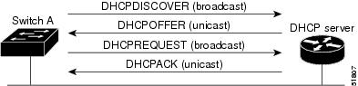
This is the sequence of messages that are exchanged between the DHCP client and the DHCP server.
The client, Switch A, broadcasts a DHCPDISCOVER message to locate a DHCP server. The DHCP server offers configuration parameters (such as an IP address, subnet mask, gateway IP address, DNS IP address, a lease for the IP address, and so forth) to the client in a DHCPOFFER unicast message.
In a DHCPREQUEST broadcast message, the client returns a formal request for the offered configuration information to the DHCP server. The formal request is broadcast so that all other DHCP servers that received the DHCPDISCOVER broadcast message from the client can reclaim the IP addresses that they offered to the client.
The DHCP server confirms that the IP address has been allocated to the client by returning a DHCPACK unicast message to the client. With this message, the client and server are bound, and the client uses configuration information received from the server. The amount of information the switch receives depends on how you configure the DHCP server.
If the configuration parameters sent to the client in the DHCPOFFER unicast message are invalid (a configuration error exists), the client returns a DHCPDECLINE broadcast message to the DHCP server.
The DHCP server sends the client a DHCPNAK denial broadcast message, which means that the offered configuration parameters have not been assigned, that an error has occurred during the negotiation of the parameters, or that the client has been slow in responding to the DHCPOFFER message (the DHCP server assigned the parameters to another client).
A DHCP client might receive offers from multiple DHCP or BOOTP servers and can accept any of the offers; however, the client usually accepts the first offer it receives. The offer from the DHCP server is not a guarantee that the IP address is allocated to the client; however, the server usually reserves the address until the client has had a chance to formally request the address. If the switch accepts replies from a BOOTP server and configures itself, the switch broadcasts, instead of unicasts, TFTP requests to obtain the switch configuration file.
The DHCP hostname option allows a group of switches to obtain hostnames and a standard configuration from the central management DHCP server. A client (switch) includes in its DCHPDISCOVER message an option 12 field used to request a hostname and other configuration parameters from the DHCP server. The configuration files on all clients are identical except for their DHCP-obtained hostnames.
If a client has a default hostname (the hostname name global configuration command is not configured or the no hostname global configuration command is entered to remove the hostname), the DHCP hostname option is not included in the packet when you enter the ip address dhcp interface configuration command. In this case, if the client receives the DCHP hostname option from the DHCP interaction while acquiring an IP address for an interface, the client accepts the DHCP hostname option and sets the flag to show that the system now has a hostname configured.
DHCP-based Autoconfiguration and Image Update
You can use the DHCP image upgrade features to configure a DHCP server to download both a new image and a new configuration file to one or more switches in a network. Simultaneous image and configuration upgrade for all switches in the network helps ensure that each new switch added to a network are synchronous with the network.
There are two types of DHCP image upgrades: DHCP autoconfiguration and DHCP auto-image update.
Restrictions for DHCP-based Autoconfiguration
- The DHCP-based autoconfiguration with a saved configuration process stops if there is not at least one Layer 3 interface in an up state without an assigned IP address in the network.
- Unless you configure a timeout, the DHCP-based autoconfiguration with a saved configuration feature tries indefinitely to download an IP address.
- The auto-install process stops if a configuration file cannot be downloaded or if the configuration file is corrupted.
- The configuration file that is downloaded from TFTP is merged with the existing configuration in the running configuration but is not saved in the NVRAM unless you enter the write memory or copy running-configuration startup-configuration privileged EXEC command. If the downloaded configuration is saved to the startup configuration, the feature is not triggered during subsequent system restarts.
DHCP Autoconfiguration
DHCP autoconfiguration downloads a configuration file to one or more switches in your network from a DHCP server. The downloaded configuration file becomes the running configuration of the switch. It does not over write the bootup configuration saved in the flash, until you reload the switch.
DHCP Auto-Image Update
You can use DHCP auto-image upgrade with DHCP autoconfiguration to download both a configuration and a new image to one or more switches in your network. The switch (or switches) downloading the new configuration and the new image can be blank (or only have a default factory configuration loaded).
To enable a DHCP auto-image update on the switch, the TFTP server where the image and configuration files are located must be configured with the correct option 67 (the configuration filename), option 66 (the DHCP server hostname) option 150 (the TFTP server address), and option 125 (description of the Cisco IOS image file) settings.
After you install the switch in your network, the auto-image update feature starts. The downloaded configuration file is saved in the running configuration of the switch, and the new image is downloaded and installed on the switch. When you reboot the switch, the configuration is stored in the saved configuration on the switch.
DHCP Server Configuration Guidelines
Follow these guidelines if you are configuring a device as a DHCP server:
- You should configure the DHCP server with reserved leases that are bound to each switch by the switch hardware address.
- If you want the switch to receive IP address information, you must configure the DHCP server with these lease options:
- If you want the switch to receive the configuration file from a TFTP server, you must configure the DHCP server with these lease options:
- Depending on the settings of the DHCP server, the switch can receive IP address information, the configuration file, or both.
- If you do not configure the DHCP server with the lease options described previously, it replies to client requests with only those parameters that are configured. If the IP address and the subnet mask are not in the reply, the switch is not configured. If the router IP address or the TFTP server name are not found, the switch might send broadcast, instead of unicast, TFTP requests. Unavailability of other lease options does not affect autoconfiguration.
- The switch can act as a DHCP server. By default, the Cisco IOS DHCP server and relay agent features are enabled on your switch but are not configured.
Purpose of the TFTP Server
Based on the DHCP server configuration, the switch attempts to download one or more configuration files from the TFTP server. If you configured the DHCP server to respond to the switch with all the options required for IP connectivity to the TFTP server, and if you configured the DHCP server with a TFTP server name, address, and configuration filename, the switch attempts to download the specified configuration file from the specified TFTP server.
If you did not specify the configuration filename, the TFTP server, or if the configuration file could not be downloaded, the switch attempts to download a configuration file by using various combinations of filenames and TFTP server addresses. The files include the specified configuration filename (if any) and these files: network-config, cisconet.cfg, hostname.config, or hostname.cfg, where hostname is the switch’s current hostname. The TFTP server addresses used include the specified TFTP server address (if any) and the broadcast address (255.255.255.255).
For the switch to successfully download a configuration file, the TFTP server must contain one or more configuration files in its base directory. The files can include these files:
- The configuration file named in the DHCP reply (the actual switch configuration file).
- The network-confg or the cisconet.cfg file (known as the default configuration files).
- The router-confg or the ciscortr.cfg file (These files contain commands common to all switches. Normally, if the DHCP and TFTP servers are properly configured, these files are not accessed.)
If you specify the TFTP server name in the DHCP server-lease database, you must also configure the TFTP server name-to-IP-address mapping in the DNS-server database.
If the TFTP server to be used is on a different LAN from the switch, or if it is to be accessed by the switch through the broadcast address (which occurs if the DHCP server response does not contain all the required information described previously), a relay must be configured to forward the TFTP packets to the TFTP server. The preferred solution is to configure the DHCP server with all the required information.
Purpose of the DNS Server
The DHCP server uses the DNS server to resolve the TFTP server name to an IP address. You must configure the TFTP server name-to-IP address map on the DNS server. The TFTP server contains the configuration files for the switch.
You can configure the IP addresses of the DNS servers in the lease database of the DHCP server from where the DHCP replies will retrieve them. You can enter up to two DNS server IP addresses in the lease database.
The DNS server can be on the same LAN or on a different LAN from the switch. If it is on a different LAN, the switch must be able to access it through a router.
How to Obtain Configuration Files
Depending on the availability of the IP address and the configuration filename in the DHCP reserved lease, the switch obtains its configuration information in these ways:
- The IP address and the configuration filename is reserved for the switch and provided in the DHCP reply (one-file read method). The switch receives its IP address, subnet mask, TFTP server address, and the configuration filename from the DHCP server. The switch sends a unicast message to the TFTP server to retrieve the named configuration file from the base directory of the server and upon receipt, it completes its boot up process.
- The IP address and the configuration filename is reserved for the switch, but the TFTP server address is not provided in the DHCP reply (one-file read method). The switch receives its IP address, subnet mask, and the configuration filename from the DHCP server. The switch sends a broadcast message to a TFTP server to retrieve the named configuration file from the base directory of the server, and upon receipt, it completes its boot-up process.
- Only the IP address is reserved for the switch and provided in the DHCP reply. The configuration filename is not provided (two-file read method). The switch receives its IP address, subnet mask, and the TFTP server address from the DHCP server. The switch sends a unicast message to the TFTP server to retrieve the network-confg or cisconet.cfg default configuration file. (If the network-confg file cannot be read, the switch reads the cisconet.cfg file.) The default configuration file contains the hostnames-to-IP-address mapping for the switch. The switch fills its host table with the information in the file and obtains its hostname. If the hostname is not found in the file, the switch uses the hostname in the DHCP reply. If the hostname is not specified in the DHCP reply, the switch uses the default Switch as its hostname. After obtaining its hostname from the default configuration file or the DHCP reply, the switch reads the configuration file that has the same name as its hostname (hostname-confg or hostname.cfg, depending on whether network-confg or cisconet.cfg was read earlier) from the TFTP server. If the cisconet.cfg file is read, the filename of the host is truncated to eight characters. If the switch cannot read the network-confg, cisconet.cfg, or the hostname file, it reads the router-confg file. If the switch cannot read the router-confg file, it reads the ciscortr.cfg file.
Note
The switch broadcasts TFTP server requests if the TFTP server is not obtained from the DHCP replies, if all attempts to read the configuration file through unicast transmissions fail, or if the TFTP server name cannot be resolved to an IP address.
How to Control Environment Variables
With a normally operating switch, you enter the boot loader mode only through the console connection configured for 9600 bps. Unplug the switch power cord, and press the Mode button while reconnecting the power cord. You can release the Mode button after all the amber system LEDs turn on and remain solid. The boot loader switch prompt then appears.
The switch boot loader software provides support for nonvolatile environment variables, which can be used to control how the boot loader, or any other software running on the system, operates. Boot loader environment variables are similar to environment variables that can be set on UNIX or DOS systems.
Environment variables that have values are stored in flash memory outside of the flash file system.
Each line in these files contains an environment variable name and an equal sign followed by the value of the variable. A variable has no value if it is not present; it has a value if it is listed even if the value is a null string. A variable that is set to a null string (for example, “ ”) is a variable with a value. Many environment variables are predefined and have default values.
You can change the settings of the environment variables by accessing the boot loader or by using Cisco IOS commands. Under normal circumstances, it is not necessary to alter the setting of the environment variables.
Environment Variables for TFTP
When the switch is connected to a PC through the Ethernet management port, you can download or upload a configuration file to the boot loader by using TFTP. Make sure the environment variables in this table are configured.
Table 2 Environment Variables for TFTPVariable
Description
MAC_ADDR
Specifies the MAC address of the switch.
Note We recommend that you do not modify this variable.
However, if you modify this variable after the boot loader is up or the value is different from the saved value, enter this command before using TFTP.
IP_ADDR
Specifies the IP address and the subnet mask for the associated IP subnet of the switch.
DEFAULT_ROUTER
Specifies the IP address and subnet mask of the default gateway.
Scheduled Reload of the Software Image
You can schedule a reload of the software image to occur on the switch at a later time (for example, late at night or during the weekend when the switch is used less), or you can synchronize a reload network-wide (for example, to perform a software upgrade on all switches in the network).
Note
A scheduled reload must take place within approximately 24 days.
You have these reload options:
- Reload of the software to take affect in the specified minutes or hours and minutes. The reload must take place within approximately 24 hours. You can specify the reason for the reload in a string up to 255 characters in length.
- Reload of the software to take place at the specified time (using a 24-hour clock). If you specify the month and day, the reload is scheduled to take place at the specified time and date. If you do not specify the month and day, the reload takes place at the specified time on the current day (if the specified time is later than the current time) or on the next day (if the specified time is earlier than the current time). Specifying 00:00 schedules the reload for midnight.
The reload command halts the system. If the system is not set to manually boot up, it reboots itself.
If your switch is configured for manual booting, do not reload it from a virtual terminal. This restriction prevents the switch from entering the boot loader mode and then taking it from the remote user’s control.
If you modify your configuration file, the switch prompts you to save the configuration before reloading. During the save operation, the system requests whether you want to proceed with the save if the CONFIG_FILE environment variable points to a startup configuration file that no longer exists. If you proceed in this situation, the system enters setup mode upon reload.
To cancel a previously scheduled reload, use the reload cancel privileged EXEC command.
How to Perform Switch Setup Configuration
Using DHCP to download a new image and a new configuration to a switch requires that you configure at least two switches. One switch acts as a DHCP and TFTP server and the second switch (client) is configured to download either a new configuration file or a new configuration file and a new image file.
- Configuring DHCP Autoconfiguration (Only Configuration File)
- Configuring DHCP Auto-Image Update (Configuration File and Image)
- Configuring the Client to Download Files from DHCP Server
- Manually Assigning IP Information to Multiple SVIs
- Modifying the Switch Startup Configuration
Configuring DHCP Autoconfiguration (Only Configuration File)
SUMMARY STEPSThis task describes how to configure DHCP autoconfiguration of the TFTP and DHCP settings on an existing switch in the network so that it can support the autoconfiguration of a new switch.
1. configure terminal
2. ip dhcp pool poolname
3. boot filename
4. network network-number mask prefix-length
5. default-router address
6. option 150 address
7. exit
8. tftp-server flash:filename.text
9. interface interface-id
10. no switchport
11. ip address address mask
12. end
DETAILED STEPSRelated References
Configuring DHCP Auto-Image Update (Configuration File and Image)
This task describes DHCP autoconfiguration to configure TFTP and DHCP settings on an existing switch to support the installation of a new switch.
Before You BeginSUMMARY STEPSYou must first create a text file (for example, autoinstall_dhcp) that will be uploaded to the switch. In the text file, put the name of the image that you want to download.
1. configure terminal
2. ip dhcp pool poolname
3. boot filename
4. network network-number mask prefix-length
5. default-router address
6. option 150 address
7. option 125 hex
8. copy tftp flash filename.txt
9. copy tftp flash imagename.bin
10. exit
11. tftp-server flash: config.text
12. tftp-server flash: imagename.bin
13. tftp-server flash: filename.txt
14. interface interface-id
15. no switchport
16. ip address address mask
17. end
18. copy running-config startup-config
DETAILED STEPS
Command or Action Purpose
Step 1 configure terminal
Example:Switch# configure terminalEnters global configuration mode.
Step 2 ip dhcp pool poolname
Example:Switch(config)# ip dhcp pool pool1Creates a name for the DHCP server address pool and enter DHCP pool configuration mode.
Step 3 boot filename
Example:Switch(dhcp-config)# boot config-boot.textSpecifies the name of the file that is used as a boot image.
Step 4 network network-number mask prefix-length
Example:Switch(dhcp-config)# network 10.10.10.0 255.255.255.0Specifies the subnet network number and mask of the DHCP address pool.
Note The prefix length specifies the number of bits that comprise the address prefix. The prefix is an alternative way of specifying the network mask of the client. The prefix length must be preceded by a forward slash (/).
Step 5 default-router address
Example:Switch(dhcp-config)# default-router 10.10.10.1Specifies the IP address of the default router for a DHCP client.
Step 6 option 150 address
Example:Switch(dhcp-config)# option 150 10.10.10.1Specifies the IP address of the TFTP server.
Step 7 option 125 hex
Example:Switch(dhcp-config)# option 125 hex 0000.0009.0a05.08661.7574.6f69.6e73.7461.6c6c.5f64.686370Specifies the path to the text file that describes the path to the image file.
Step 8 copy tftp flash filename.txt
Example:Switch(config)# copy tftp flash image.binUploads the text file to the switch.
Step 9 copy tftp flash imagename.bin
Example:Switch(config)# copy tftp flash image.binUploads the tar file for the new image to the switch.
Step 10 exit
Example:Switch(dhcp-config)# exitReturns to global configuration mode.
Step 11 tftp-server flash: config.text
Example:Switch(config)# tftp-server flash:config-boot.textSpecifies the Cisco IOS configuration file on the TFTP server.
Step 12 tftp-server flash: imagename.bin
Example:Switch(config)# tftp-server flash:image.binSpecifies the image name on the TFTP server.
Step 13 tftp-server flash: filename.txt
Example:Switch(config)# tftp-server flash:boot-config.textSpecifies the text file that contains the name of the image file to download
Step 14 interface interface-id
Example:Switch(config)# interface gigabitEthernet1/0/4Specifies the address of the client that will receive the configuration file.
Step 15 no switchport
Example:Switch(config-if)# no switchportPuts the interface into Layer 3 mode.
Step 16 ip address address mask
Example:Switch(config-if)# ip address 10.10.10.1 255.255.255.0Specifies the IP address and mask for the interface.
Step 17 end
Example:Switch(config-if)# endReturns to privileged EXEC mode.
Step 18 copy running-config startup-config
Example:Switch(config-if)# end(Optional) Saves your entries in the configuration file.
Related References
Configuring the Client to Download Files from DHCP Server
SUMMARY STEPS
Note
You should only configure and enable the Layer 3 interface. Do not assign an IP address or DHCP-based autoconfiguration with a saved configuration.
1. configure terminal
2. boot host dhcp
3. boot host retry timeout timeout-value
4. banner config-save ^C warning-message ^C
5. end
6. show boot
DETAILED STEPS
Command or Action Purpose
Step 1 configure terminal
Example:Switch# configure terminalEnters global configuration mode.
Step 2 boot host dhcp
Example:Switch(conf)# boot host dhcpEnables autoconfiguration with a saved configuration.
Step 3 boot host retry timeout timeout-value
Example:Switch(conf)# boot host retry timeout 300(Optional) Sets the amount of time the system tries to download a configuration file.
Note If you do not set a timeout, the system will try indefinitely to obtain an IP address from the DHCP server.
Step 4 banner config-save ^C warning-message ^C
Example:Switch(conf)# banner config-save ^C Caution - Saving Configuration File to NVRAM May Cause You to No longer Automatically Download Configuration Files at Reboot^C(Optional) Creates warning messages to be displayed when you try to save the configuration file to NVRAM.
Step 5 end
Example:Switch(config-if)# endReturns to privileged EXEC mode.
Step 6 show boot
Example:Switch# show bootVerifies the configuration.
Related References
Manually Assigning IP Information to Multiple SVIs
SUMMARY STEPSThis task describes how to manually assign IP information to multiple switched virtual interfaces (SVIs):
Note
If the switch is running the IP services feature set, you can also manually assign IP information to a port if you first put the port into Layer 3 mode by using the no switchport interface configuration command.
1. configure terminal
2. interface vlan vlan-id
3. ip address ip-address subnet-mask
4. exit
5. ip default-gateway ip-address
6. end
7. show interfaces vlan vlan-id
8. show ip redirects
DETAILED STEPS
Command or Action Purpose
Step 1 configure terminal
Example:Switch# configure terminalEnters global configuration mode.
Step 2 interface vlan vlan-id
Example:Switch(config)# interface vlan 99Enters interface configuration mode, and enters the VLAN to which the IP information is assigned. The range is 1 to 4094.
Step 3 ip address ip-address subnet-mask
Example:Switch(config-vlan)# ip address 10.10.10.2 255.255.255.0Enters the IP address and subnet mask.
Step 4 exit
Example:Switch(config-vlan)# exitReturns to global configuration mode.
Step 5 ip default-gateway ip-address
Example:Switch(config)# ip default-gateway 10.10.10.1Enters the IP address of the next-hop router interface that is directly connected to the switch where a default gateway is being configured. The default gateway receives IP packets with unresolved destination IP addresses from the switch.
Once the default gateway is configured, the switch has connectivity to the remote networks with which a host needs to communicate.
Note When your switch is configured to route with IP, it does not need to have a default gateway set.
Note The switch capwap relays on default-gateway configuration to support routed access point join the switch.
Step 6 end
Example:Switch(config)# endReturns to privileged EXEC mode.
Step 7 show interfaces vlan vlan-id
Example:Switch# show interfaces vlan 99Verifies the configured IP address.
Step 8 show ip redirects
Example:Switch# show ip redirectsVerifies the configured default gateway.
Modifying the Switch Startup Configuration
- Specifying the Filename to Read and Write the System Configuration
- Manually Booting the Switch
- Booting the Switch in Installed Mode
- Booting the Switch in Bundle Mode
- Booting a Specific Software Image On a Switch Stack
- Configuring a Scheduled Software Image Reload
Specifying the Filename to Read and Write the System Configuration
SUMMARY STEPSBy default, the Cisco IOS software uses the config.text file to read and write a nonvolatile copy of the system configuration. However, you can specify a different filename, which will be loaded during the next boot cycle.
1. configure terminal
2. boot flash:/file-url
3. end
4. show boot
5. copy running-config startup-config
DETAILED STEPS
Command or Action Purpose
Step 1 configure terminal
Example:Switch# configure terminalEnters global configuration mode.
Step 2 boot flash:/file-url
Example:Switch(config)# boot flash:config.textSpecifies the configuration file to load during the next boot cycle.
file-url—The path (directory) and the configuration filename.
Filenames and directory names are case-sensitive.
Step 3 end
Example:Switch(config)# endReturns to privileged EXEC mode.
Step 4 show boot
Example:Switch# show bootVerifies your entries.
The boot global configuration command changes the setting of the CONFIG_FILE environment variable.
Step 5 copy running-config startup-config
Example:Switch# copy running-config startup-config(Optional) Saves your entries in the configuration file.
Manually Booting the Switch
SUMMARY STEPS
1. configure terminal
2. boot manual
3. end
4. show boot
5. copy running-config startup-config
DETAILED STEPS
Command or Action Purpose
Step 1 configure terminal
Example:Switch# configure terminalEnters global configuration mode.
Step 2 boot manual
Example:Switch(config)# boot manualEnables the switch to manually boot up during the next boot cycle.
Step 3 end
Example:Switch(config)# endReturns to privileged EXEC mode.
Step 4 show boot
Example:Switch# show bootVerifies your entries.
The boot manual global command changes the setting of the MANUAL_BOOT environment variable.
Filenames and directory names are case-sensitive.
Step 5 copy running-config startup-config
Example:Switch# copy running-config startup-config(Optional) Saves your entries in the configuration file.
Booting the Switch in Installed Mode
SUMMARY STEPS
1. cp source_file_path destination_file_path
2. software expand file source_file_path
3. reload
4. boot flash:packages.conf
5. show version
DETAILED STEPS
Command or Action Purpose
Step 1 cp source_file_path destination_file_path
Example:Switch# copy tftp://10.0.0.6/cat3k_caa-universalk9.SSA.03.12.02.EZP.150-12.02.EZP.150-12.02.EZP.bin flash:(Optional) Copies the bin file (image.bin) from the FTP or TFTP server to flash or USB flash.
Step 2 software expand file source_file_path
Example:Expanding the bin file from the TFTP server:Switch# software expand file tftp://10.0.0.2/cat3k_caa-universalk9.SSA.03.09.37.EXP.150-9.37.EXP.bin to flash: Preparing expand operation ... [1]: Downloading file tftp://10.0.0.2/cat3k_caa-universalk9.SSA.03.09.37.EXP.150-9.37.EXP.bin to active switch 1 [1]: Finished downloading file tftp://10.0.0.2/cat3k_caa-universalk9.SSA.03.09.37.EXP.150-9.37. EXP.bin to active switch 1 [1]: Copying software from active switch 1 to switch 2 [1]: Finished copying software to switch 2 [1 2]: Expanding bundle cat3k_caa-universalk9.SSA.03.09.37.EXP.150-9.37.EXP.bin [1 2]: Copying package files [1 2]: Package files copied [1 2]: Finished expanding bundle cat3k_caa-universalk9.SSA.03.09.37.EXP.150-9.37.EXP.bin 18 -rw- 74387812 Dec 7 2012 05:55:43 +00:00 cat3k_caa-base.SSA.03.09.37.EXP.pkg 19 -rw- 2738868 Dec 7 2012 05:55:44 +00:00 cat3k_caa-drivers.SSA.03.09.37.EXP.pkg 20 -rw- 32465772 Dec 7 2012 05:55:44 +00:00 cat3k_caa-infra.SSA.03.09.37.EXP.pkg 21 -rw- 30389036 Dec 7 2012 05:55:44 +00:00 cat3k_caa-iosd-universalk9.SSA.150-9.37.EXP.pkg 22 -rw- 18342624 Dec 7 2012 05:55:44 +00:00 cat3k_caa-platform.SSA.03.09.37.EXP.pkg 23 -rw- 63374028 Dec 7 2012 05:55:44 +00:00 cat3k_caa-wcm.SSA.10.0.10.14.pkg 17 -rw- 1239 Dec 7 2012 05:56:29 +00:00 packages.confExpands the bin file stored in flash, FTP, TFTP, HTTP, or HTTPS server on the booted switch.
Note Ensure that the packages.conf file is available in the expanded list.
Step 3 reload
Example:Switch: reloadReloads the switch.
Note You can boot the switch manually or automatically using the packages.conf file. If you are booting manually, you can proceed to Step 4. Otherwise, the switch boots up automatically.
Step 4 boot flash:packages.conf
Example:switch: boot flash:packages.confBoots the switch with the packages.conf file.
Step 5 show version
Example:switch# show version Switch Ports Model SW Version SW Image Mode ------ ----- ----- ---------- ---------- ---- 1 6 WS-C3850-6DS-S 03.09.26.EXP ct3850-ipservicesk9 INSTALLVerifies that the switch is in the INSTALL mode.
Booting the Switch in Bundle Mode
SUMMARY STEPSThere are several methods by which you can boot the switch—either by copying the bin file from the TFTP server and then boot the switch, or by booting the switch straight from flash or USB flash using the commands boot flash:<image.bin> or boot usbflash0:<image.bin> .
The following procedure explains how to boot the switch from th TFTP server in the bundle mode.
1. cp source_file_path destination_file_path
2. switch:BOOT=<source path of .bin file>
3. boot
4. show version
DETAILED STEPS
Command or Action Purpose
Step 1 cp source_file_path destination_file_path
Example:Switch# copy tftp://10.0.0.6/cat3k_caa-universalk9.SSA.03.12.02.EZP.150-12.02.EZP.150-12.02.EZP.bin flash:(Optional) Copies the bin file (image.bin) from the FTP or TFTP server to flash or USB flash.
Step 2 switch:BOOT=<source path of .bin file>
Example:Switch: switch:BOOT=tftp://10.0.0.2/cat3k_caa-universalk9.SSA.03.09.37.EXP.150-9.37.EXP.binSets the boot parameters.
Step 3 boot
Example:switch: bootBoots the switch.
Step 4 show version
Example:switch# show version Switch Ports Model SW Version SW Image Mode ------ ----- ----- ---------- ---------- ---- 1 6 WS-C3850-6DS-S 03.09.40.EXP ct3850-ipservicesk9 BUNDLEVerifies that the switch is in the BUNDLE mode.
Booting a Specific Software Image On a Switch Stack
SUMMARY STEPS
1. configure terminal
2. boot system switch {number | all} flash:image_file| tftp: image_file | usbflash0: image_file
3. end
4. show boot system
5. copy running-config startup-config
DETAILED STEPS
Command or Action Purpose
Step 1 configure terminal
Example:Switch# configure terminalEnters global configuration mode.
Step 2 boot system switch {number | all} flash:image_file| tftp: image_file | usbflash0: image_file
Example:Switch(config)# boot system switch 2 flash:cat3850-universalk9.SSA.03.08.83.EMD.150-8.83.EMD.bin(Optional) For switches in a stack, specifies the switch members on which the system image is loaded during the next boot cycle:
Step 3 end
Example:Switch(config)# endReturns to privileged EXEC mode.
Step 4 show boot system
Example:Switch# show boot systemVerifies your entries.
The boot system global command changes the setting of the BOOT environment variable.
During the next boot cycle, the switch attempts to automatically boot up the system using information in the BOOT environment variable.
Step 5 copy running-config startup-config
Example:Switch# copy running-config startup-config(Optional) Saves your entries in the configuration file.
Configuring a Scheduled Software Image Reload
SUMMARY STEPS
1. configure terminal
2. copy running-config startup-config
3. reload in [hh:]mm [text]
4. reload slot [stack-member-number]
5. reload at hh: mm [month day | day month] [text]
6. reload cancel
7. show reload
DETAILED STEPS
Command or Action Purpose
Step 1 configure terminal
Example:Switch# configure terminalEnters global configuration mode.
Step 2 copy running-config startup-config
Example:copy running-config startup-configSaves your switch configuration information to the startup configuration before you use the reload command.
Step 3 reload in [hh:]mm [text]
Example:Switch(config)# reload in 12 System configuration has been modified. Save? [yes/no]: ySchedules a reload of the software to take affect in the specified minutes or hours and minutes. The reload must take place within approximately 24 days. You can specify the reason for the reload in a string up to 255 characters in length.
Step 4 reload slot [stack-member-number]
Example:Switch(config)# reload slot 6 Proceed with reload? [confirm] ySchedules a reload of the software in a switch stack.
Step 5 reload at hh: mm [month day | day month] [text]
Example:Switch(config)# reload at 14:00Specifies the time in hours and minutes for the reload to occur.
Note Use the at keyword only if the switch system clock has been set (through Network Time Protocol (NTP), the hardware calendar, or manually). The time is relative to the configured time zone on the switch. To schedule reloads across several switches to occur simultaneously, the time on each switch must be synchronized with NTP.
Step 6 reload cancel
Example:Switch(config)# reload cancelCancels a previously scheduled reload. Step 7 show reload
Example:show reloadDisplays information about a previously scheduled reload or identifies if a reload has been scheduled on the switch.
Monitoring Switch Setup Configuration
- Example: Verifying the Switch Running Configuration
- Examples: Displaying Software Bootup in Install Mode
- Example: Emergency Installation
Example: Verifying the Switch Running Configuration
Switch# show running-config
Building configuration...

Current configuration: 1363 bytes
!
version 12.4
no service pad
service timestamps debug uptime
service timestamps log uptime
no service password-encryption
!
hostname Stack1
!
enable secret 5 $1$ej9.$DMUvAUnZOAmvmgqBEzIxE0
!
.
<output truncated>
.
interface gigabitethernet6/0/2
mvr type source

<output truncated>

...!
interface VLAN1
 ip address 172.20.137.50 255.255.255.0
 no ip directed-broadcast
!
ip default-gateway 172.20.137.1 !
!
snmp-server community private RW
snmp-server community public RO
snmp-server community private@es0 RW
snmp-server community public@es0 RO
snmp-server chassis-id 0x12
!
end
Examples: Displaying Software Bootup in Install Mode
This example displays software bootup in install mode:switch: boot flash:packages.conf Getting rest of image Reading full image into memory....done Reading full base package into memory...: done = 74596432 Nova Bundle Image -------------------------------------- Kernel Address : 0x6042f354 Kernel Size : 0x318412/3245074 Initramfs Address : 0x60747768 Initramfs Size : 0xdc08e8/14420200 Compression Format: .mzip Bootable image at @ ram:0x6042f354 Bootable image segment 0 address range [0x81100000, 0x81b80000] is in range [0x80180000, 0x90000000]. @@@@@@@@@@@@@@@@@@@@@@@@@@@@@@@@@@@@@@@@@@@@@@@@@@@@@@@@@@@@@@@@@@@@@@@@@@@@@@@@@@boot_system: 377 Loading Linux kernel with entry point 0x811060f0 ... Bootloader: Done loading app on core_mask: 0xf ### Launching Linux Kernel (flags = 0x5) All packages are Digitally Signed Starting System Services Nov 7 09:57:05 %IOSXE-1-PLATFORM: process stack-mgr: %STACKMGR-1-DISC_START: Switch 2 is starting stack discovery ####################################################################################################################### Nov 7 09:59:07 %IOSXE-1-PLATFORM: process stack-mgr: %STACKMGR-1-DISC_DONE: Switch 2 has finished stack discovery Nov 7 09:59:07 %IOSXE-1-PLATFORM: process stack-mgr: %STACKMGR-1-SWITCH_ADDED: Switch 2 has been added to the stack Nov 7 09:59:14 %IOSXE-1-PLATFORM: process stack-mgr: %STACKMGR-1-ACTIVE_ELECTED: Switch 2 has been elected ACTIVE Restricted Rights Legend Use, duplication, or disclosure by the Government is subject to restrictions as set forth in subparagraph (c) of the Commercial Computer Software - Restricted Rights clause at FAR sec. 52.227-19 and subparagraph (c) (1) (ii) of the Rights in Technical Data and Computer Software clause at DFARS sec. 252.227-7013. cisco Systems, Inc. 170 West Tasman Drive San Jose, California 95134-1706 Cisco IOS Software, IOS-XE Software, Catalyst L3 Switch Software (CAT3K_CAA-UNIVERSALK9-M), Version 03.09.12.EMD EARLY DEPLOYMENT ENGINEERING NOVA_WEEKLY BUILD, synced to DSGS_PI2_POSTPC_FLO_DSBU7_NG3K_1105 Copyright (c) 1986-2012 by Cisco Systems, Inc. Compiled Sun 04-Nov-12 22:53 by gereddy License level to iosd is ipservicesThis example display software bootup in bundle mode:switch: boot flash:cat3k_caa-universalk9.SSA.03.09.12.EMD.150-9.12.EMD.bin Reading full image into memory..................................................................done Nova Bundle Image -------------------------------------- Kernel Address : 0x6042ff38 Kernel Size : 0x318412/3245074 Initramfs Address : 0x6074834c Initramfs Size : 0xdc08e8/14420200 Compression Format: .mzip Bootable image at @ ram:0x6042ff38 Bootable image segment 0 address range [0x81100000, 0x81b80000] is in range [0x80180000, 0x90000000]. @@@@@@@@@@@@@@@@@@@@@@@@@@@@@@@@@@@@@@@@@@@@@@@@@@@@@@@@@@@@@@@@@@@@@@@@@@@@@@@@@@ File "flash:cat3k_caa-universalk9.SSA.03.09.12.EMD.150-9.12.EMD.bin" uncompressed and installed, entry point: 0x811060f0 Loading Linux kernel with entry point 0x811060f0 ... Bootloader: Done loading app on core_mask: 0xf ### Launching Linux Kernel (flags = 0x5) All packages are Digitally Signed Starting System Services Nov 7 09:45:49 %IOSXE-1-PLATFORM: process stack-mgr: %STACKMGR-1-DISC_START: Switch 2 is starting stack discovery ####################################################################################################################### Nov 7 09:47:50 %IOSXE-1-PLATFORM: process stack-mgr: %STACKMGR-1-DISC_DONE: Switch 2 has finished stack discovery Nov 7 09:47:50 %IOSXE-1-PLATFORM: process stack-mgr: %STACKMGR-1-SWITCH_ADDED: Switch 2 has been added to the stack Nov 7 09:47:58 %IOSXE-1-PLATFORM: process stack-mgr: %STACKMGR-1-ACTIVE_ELECTED: Switch 2 has been elected ACTIVE Restricted Rights Legend Use, duplication, or disclosure by the Government is subject to restrictions as set forth in subparagraph (c) of the Commercial Computer Software - Restricted Rights clause at FAR sec. 52.227-19 and subparagraph (c) (1) (ii) of the Rights in Technical Data and Computer Software clause at DFARS sec. 252.227-7013. cisco Systems, Inc. 170 West Tasman Drive San Jose, California 95134-1706 Cisco IOS Software, IOS-XE Software, Catalyst L3 Switch Software (CAT3K_CAA-UNIVERSALK9-M), Version 03.09.12.EMD EARLY DEPLOYMENT ENGINEERING NOVA_WEEKLY BUILD, synced to DSGS_PI2_POSTPC_FLO_DSBU7_NG3K_1105 Copyright (c) 1986-2012 by Cisco Systems, Inc. Compiled Sun 04-Nov-12 22:53 by gereddy License level to iosd is ipservicesExample: Emergency Installation
This sample output is an example when the emergency-install boot command is initiated:
switch: emergency-install tftp://192.0.2.47/cat3k/cat3k_caa-universalk9.SSA.03.09.12.EMD.150-9.12.EMD.bin The bootflash will be erased during install operation, continue (y/n)?y Starting emergency recovery (tftp://192.0.2.47/cat3k/cat3k_caa-universalk9.SSA.03.09.12.EMD.150-9.12.EMD.bin)... Reading full image into memory......................done Nova Bundle Image -------------------------------------- Kernel Address : 0x6042e5cc Kernel Size : 0x318261/3244641 Initramfs Address : 0x60746830 Initramfs Size : 0xdb0fb9/14356409 Compression Format: .mzip Bootable image at @ ram:0x6042e5cc Bootable image segment 0 address range [0x81100000, 0x81b80000] is in range [0x80180000, 0x90000000]. @@@@@@@@@@@@@@@@@@@@@@@@@@@@@@@@@@@@@@@@@@@@@@@@@@@@@@@@@@@@@@@@@@@@@@@@@@@@@@@@@@ File "sda9:c3850-recovery.bin" uncompressed and installed, entry point: 0x811060f0 Loading Linux kernel with entry point 0x811060f0 ... Bootloader: Done loading app on core_mask: 0xf ### Launching Linux Kernel (flags = 0x5) Initiating Emergency Installation of bundle tftp://172.19.211.47/cstohs/cat3k_caa-universalk9.SSA.03.09.12.EMD.150-9.12.EMD.bin Downloading bundle tftp://192.0.2.47/cat3k/cat3k_caa-universalk9.SSA.03.09.12.EMD.150-9.12.EMD.bin... Validating bundle tftp://192.0.2.47/cat3k/cat3k_caa-universalk9.SSA.03.09.12.EMD.150-9.12.EMD.bin... Installing bundle tftp://192.0.2.47/cat3k/cat3k_caa-universalk9.SSA.03.09.12.EMD.150-9.12.EMD.bin... Verifying bundle tftp://192.0.2.47/cat3k/cat3k_caa-universalk9.SSA.03.09.12.EMD.150-9.12.EMD.bin... Package cat3k_caa-base.SSA.03.09.12.EMD.pkg is Digitally Signed Package cat3k_caa-drivers.SSA.03.09.12.EMD.pkg is Digitally Signed Package cat3k_caa-infra.SSA.03.09.12.EMD.pkg is Digitally Signed Package cat3k_caa-iosd-universalk9.SSA.150-9.12.EMD.pkg is Digitally Signed Package cat3k_caa-platform.SSA.03.09.12.EMD.pkg is Digitally Signed Package cat3k_caa-wcm.SSA.03.09.12.EMD.pkg is Digitally Signed Preparing flash... Syncing device... Emergency Install successful... Rebooting Restarting system. Booting...(use DDR clock 667 MHz)Initializing and Testing RAM +++@@@@####...++@@++@@++@@++@Configuration Examples for Performing Switch Setup
Example: Configuring a Switch as a DHCP Server
Switch# configure terminal Switch(config)# ip dhcp pool pool1 Switch(dhcp-config)# network 10.10.10.0 255.255.255.0 Switch(dhcp-config)# boot config-boot.text Switch(dhcp-config)# default-router 10.10.10.1 Switch(dhcp-config)# option 150 10.10.10.1 Switch(dhcp-config)# exit Switch(config)# tftp-server flash:config-boot.text Switch(config)# interface gigabitethernet1/0/4 Switch(config-if)# no switchport Switch(config-if)# ip address 10.10.10.1 255.255.255.0 Switch(config-if)# endExample: Configuring DHCP Auto-Image Update
Switch# configure terminal Switch(config)# ip dhcp pool pool1 Switch(dhcp-config)# network 10.10.10.0 255.255.255.0 Switch(dhcp-config)# boot config-boot.text Switch(dhcp-config)# default-router 10.10.10.1 Switch(dhcp-config)# option 150 10.10.10.1 Switch(dhcp-config)# option 125 hex 0000.0009.0a05.08661.7574.6f69.6e73.7461.6c6c.5f64.686370 Switch(dhcp-config)# exit Switch(config)# tftp-server flash:config-boot.text Switch(config)# tftp-server flash:image_name Switch(config)# tftp-server flash:boot-config.text Switch(config)# tftp-server flash: autoinstall_dhcp Switch(config)# interface gigabitethernet1/0/4 Switch(config-if)# no switchport Switch(config-if)# ip address 10.10.10.1 255.255.255.0 Switch(config-if)# endExample: Configuring a Switch to Download Configurations from a DHCP Server
This example uses a Layer 3 SVI interface on VLAN 99 to enable DHCP-based autoconfiguration with a saved configuration:
Switch# configure terminal Switch(conf)# boot host dhcp Switch(conf)# boot host retry timeout 300 Switch(conf)# banner config-save ^C Caution - Saving Configuration File to NVRAM May Cause You to No longer Automatically Download Configuration Files at Reboot^C Switch(config)# vlan 99 Switch(config-vlan)# interface vlan 99 Switch(config-if)# no shutdown Switch(config-if)# end Switch# show boot BOOT path-list: Config file: flash:/config.text Private Config file: flash:/private-config.text Enable Break: no Manual Boot: no HELPER path-list: NVRAM/Config file buffer size: 32768 Timeout for Config Download: 300 seconds Config Download via DHCP: enabled (next boot: enabled) Switch#Examples: Scheduling Software Image Reload
This example shows how to reload the software on the switch on the current day at 7:30 p.m:
Switch# reload at 19:30
Reload scheduled for 19:30:00 UTC Wed Jun 5 2013 (in 2 hours and 25 minutes)
Proceed with reload? [confirm]
This example shows how to reload the software on the switch at a future time:
Switch# reload at 02:00 jun 20
Reload scheduled for 02:00:00 UTC Thu Jun 20 2013 (in 344 hours and 53 minutes)
Proceed with reload? [confirm]
Additional References For Performing Switch Setup
Related Documents
Related Topic Document Title Switch setup commands
Boot loader commands
System Management Command Reference (Catalyst 3850 Switches)
Pre-download feature
System Management Configuration Guide (Cisco WLC 5700 Series)
IOS XE DHCP configuration
IP Addressing Configuration Guide Library, Cisco IOS XE Release 3S (Catalyst 3850 Switches)
Hardware installation
Catalyst 3850 Switch Hardware Installation Guide
Platform-independent command references
Configuration Fundamentals Command Reference, Cisco IOS XE Release 3S (Catalyst 3850 Switches)
Platform-independent configuration information
Configuration Fundamentals Configuration Guide, Cisco IOS XE Release 3S (Catalyst 3850 Switches)
MIBs
Technical Assistance
Description Link The Cisco Support website provides extensive online resources, including documentation and tools for troubleshooting and resolving technical issues with Cisco products and technologies.
To receive security and technical information about your products, you can subscribe to various services, such as the Product Alert Tool (accessed from Field Notices), the Cisco Technical Services Newsletter, and Really Simple Syndication (RSS) Feeds.
Access to most tools on the Cisco Support website requires a Cisco.com user ID and password.