Feedback
Contents
- Configuring Cisco CleanAir
- Finding Feature Information
- Prerequisites for CleanAir
- Restrictions for CleanAir
- Information About CleanAir
- Cisco CleanAir Components
- Terms Used in Cisco CleanAir
- Interference Types that Cisco CleanAir can Detect
- Interference Device Merging
- Persistent Devices
- Persistent Devices Detection
- Persistent Device Avoidance
- EDRRM and AQR Update Mode
- CleanAir High Availability
- How to Configure CleanAir
- Enabling CleanAir for 2.4-GHz Band
- Configuring a CleanAir Alarm for 2.4-GHz Air-Quality and Devices
- Configuring Interference Reporting for 2.4-GHz Devices
- Enabling CleanAir for 5-GHz Band
- Configuring a CleanAir Alarm for 5-GHz Air-Quality and Devices
- Configuring Interference Reporting for 5-GHz devices
- Configuring EDRRM for CleanAir-Events
- Configuring Persistent Device Avoidance
- Configuring Cisco CleanAir on the Cisco Wireless LAN Controller (GUI)
- Configuring Cisco CleanAir on an Access Point (GUI)
- Configuring Cisco Spectrum Expert
- Configuring Spectrum Expert (GUI)
- Configuring Spectrum Expert (CLI)
- Monitoring CleanAir Parameters
- Monitoring the Interference Devices
- Monitoring the Interference Devices (GUI)
- Monitoring the Worst Air Quality of Radio Bands (GUI)
- Configuration Examples for Configuring CleanAir
- CleanAir FAQs
- Additional References
Configuring Cisco CleanAir
- Finding Feature Information
- Prerequisites for CleanAir
- Restrictions for CleanAir
- Information About CleanAir
- How to Configure CleanAir
- Configuring Cisco Spectrum Expert
- Monitoring CleanAir Parameters
- Configuration Examples for Configuring CleanAir
- CleanAir FAQs
- Additional References
Finding Feature Information
Your software release may not support all of the features documented in this module. For the latest feature information and caveats, see the release notes for your platform and software release.
Use Cisco Feature Navigator to find information about platform support and Cisco software image support. To access Cisco Feature Navigator, go to http://www.cisco.com/go/cfn. An account on Cisco.com is not required.
Prerequisites for CleanAir
You can configure Cisco CleanAir only on CleanAir-enabled access points.
Only Cisco CleanAir-enabled access points using the following access point modes can perform Cisco CleanAir spectrum monitoring:
- Local—In this mode, each Cisco CleanAir-enabled access point radio provides air quality and interference detection reports for the current operating channel only.
- Monitor—When Cisco CleanAir is enabled in monitor mode, the access point provides air quality and interference detection reports for all monitored channels. The following options are available:
- SE-Connect—This mode enables a user to connect a Spectrum Expert application running on an external Microsoft Windows XP or Vista PC to a Cisco CleanAir-enabled access point in order to display and analyze detailed spectrum data. The Spectrum Expert application connects directly to the access point, bypassing the switch. An access point in SE-Connect mode does not provide any Wi-Fi, RF, or spectrum data to the switch. All CleanAir system functionality is suspended while the AP is in this mode, and no clients are served. This mode is intended for remote troubleshooting only. Up to three active Spectrum Expert connections are possible.
Related Tasks
Restrictions for CleanAir
- Access points in monitor mode do not transmit Wi-Fi traffic or 802.11 packets. They are excluded from radio resource management (RRM) planning and are not included in the neighbor access point list. IDR clustering depends on the switch’s ability to detect neighboring in-network access points. Correlating interference device detections from multiple access points is limited between monitor-mode access points.
- Cisco recommends a ratio of 1 monitor mode access point for every 5 local mode access points, this may also vary based on the network design and expert guidance for best coverage.
- Spectrum Expert (Windows XP laptop client) and AP should be pingable, otherwise; it will not work.
Information About CleanAir
Cisco CleanAir is a spectrum intelligence solution designed to proactively manage the challenges of a shared wireless spectrum. All of the users of the shared spectrum can be seen (both native devices and foreign interferers). It also enables the network to act upon this information. For example, the interfering device can be manually removed or the system can automatically change the channel away from the interference.
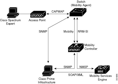
A Cisco CleanAir system consists of CleanAir-enabled access points, wireless controller modules, mobility controllers, mobility anchors and next generation switches. The access points join the mobility controller directly or through the mobility anchor. They collect information about all devices that operate in the industrial, scientific, and medical (ISM) bands, identify and evaluate the information as a potential interference source, and forward it to the switch. The switch controls the access points, collects spectrum data, and forwards information to Cisco Prime Infrastructure (PI) or a Cisco Mobility Services Engine (MSE) upon request.
Any networking configurations can be performed only on the mobility controller, configurations cannot be performed in the MA mode. However, any radio level CleanAir configurations can be done using mobility anchor.
For every device operating in the unlicensed band, Cisco CleanAir tells what it is, where it is, how it is impacting the wireless network, and what actions should be taken. It simplifies RF.
Wireless LAN systems operate in unlicensed 2.4-GHz and 5-GHz ISM bands. Many devices like microwave ovens, cordless phones, and Bluetooth devices also operate in these bands and can negatively affect the Wi-Fi operations.
Some of the most advanced WLAN services, such as voice over wireless and IEEE 802.11n radio communications, could be significantly impaired by the interference caused by other legal users of the ISM bands. The integration of Cisco CleanAir functionality addresses this problem of radio frequency (RF) interference.
- Cisco CleanAir Components
- Terms Used in Cisco CleanAir
- Interference Types that Cisco CleanAir can Detect
- Interference Device Merging
- Persistent Devices
- EDRRM and AQR Update Mode
- CleanAir High Availability
Cisco CleanAir Components
The basic Cisco CleanAir architecture consists of Cisco CleanAir-enabled APs and switch. Cisco Prime Infrastructure (PI), Mobility Services Engine (MSE) and Cisco Spectrum Expert are optional system components. Cisco PI and MSE provide user interfaces for advanced spectrum capabilities such as historic charts, tracking interference devices, location services and impact analysis.
An access point equipped with Cisco CleanAir technology collects information about non-Wi-Fi interference sources, processes it, and forwards it to the MA. The access point sends AQR and IDR reports to the controller.
The mobility controller (MC) controls and configures CleanAir-capable access points, collects and processes spectrum data, and provides it to the PI and/or the MSE. The MC provides local user interfaces (GUI and CLI) to configure basic CleanAir features and services and display current spectrum information. The MC also does detection, merging and mitigation of interference devices using RRM TPC and DCM. For details on Interference Device Merging, see Interference Device Merging.
Cisco PI provides advanced user interfaces for CleanAir that include feature enabling and configuration, consolidated display information, historic AQ records and reporting engines. PI also shows charts of interference devices, AQ trends, and alerts.
Cisco MSE is required for location and historic tracking of interference devices, and provides coordination and consolidation of interference reports across multiple controllers. MSE also provides adaptive Wireless Intrusion Prevention System (WIPS) service that provides comprehensive over-the-air threat detection, location and mitigation. MSE also merges all the interference data.
To obtain detailed spectrum data that can be used to generate RF analysis plots similar to those provided by a spectrum analyzer, you can configure a Cisco CleanAir-enabled access point to connect directly to a Microsoft Windows XP or Vista PC running the Cisco Spectrum Expert application.
The switch performs the following tasks in a Cisco CleanAir system:
- Configures Cisco CleanAir capabilities on the access point.
- Provides interfaces (GUI, CLI, and SNMP) for configuring Cisco CleanAir features and retrieving data.
- Displays spectrum data.
- Collects and processes AQRs from the access point and stores them in the air quality database. AQRs contains information about the total interference from all identified sources represented by Air Quality Index (AQI) and summary for the most severe interference categories. The CleanAir system can also include unclassified interference information under per interference type reports which enable you to take action in cases where the interference due to unclassified interfering devices is frequent.
- Collects and processes Interference Device Reports (IDRs) from the access point and stores them in the interference device database.
- Forwards spectrum data to Prime Infrastructure and the MSE.
Terms Used in Cisco CleanAir
Table 1 CleanAir-related Terms Term Decription AQI Air Quality Index. The AQI is an indicator of air quality, based on the air pollutants. An AQI of 0 is bad and an AQI > 85 is good. AQR Air Quality Report. AQRs contain information about the total interference from all identified sources represented by AQI and summary of the most severe interference categories. AQRs are sent every 15 minutes to the Mobility Controller and every 30 seconds in the Rapid mode. DC Duty Cycle. Percentage of time that the channel is utilized by a device. EDRRM EDRRM Event Driven RRM. EDRRM allows an access point in distress to bypass normal RRM intervals and immediately change channels. IDR Interference Device Reports that the access point sends to the controller. ISI Interference Severity Index. The ISI is an indicator of the severity of the interference. MA Mobility Agent. An MA is either an access switch that has a wireless module running on it or an MC with an internal MA running on it. An MA is the wireless component that maintains client mobility state machine for a mobile client that is connected to an access point to the device that the MA is running on. MC Mobility Controller. An MC provides mobility management services for inter-peer group roaming events. The MC provides a central point of contact for management and sends the configuration to all the mobility agents under its sub-domain of their mobility configuration, peer group membership and list of members. RSSI Received Signal Strength Indicator. RSSI is a measurement of the power present in a received radio signal. It is the power at which an access point sees the interferer device. Interference Types that Cisco CleanAir can Detect
Cisco CleanAir can detect interference, report on the location and severity of the interference, and recommend different mitigation strategies. Two such mitigation strategies are persistent device avoidance and spectrum event-driven RRM. New
Wi-Fi chip-based RF management systems share these characteristics:
- Any RF energy that cannot be identified as a Wi-Fi signal is reported as noise.
- Noise measurements that are used to assign a channel plan tend to be averaged over a period of time to avoid instability or rapid changes that can be disruptive to certain client devices.
- Averaging measurements reduces the resolution of the measurement. As such, a signal that disrupts clients might not look like it needs to be mitigated after averaging.
- All RF management systems available today are reactive in nature.
Cisco CleanAir is different and can positively identify not only the source of the noise but also its location and potential impact to a WLAN. Having this information allows you to consider the noise within the context of the network and make intelligent and, where possible, proactive decisions. For CleanAir, two types of interference events are common:Persistent interference events are created by devices that are stationary in nature and have intermittent but largely repeatable patterns of interference. For example, consider the case of a microwave oven located in a break room. Such a device might be active for only 1 or 2 minutes at a time. When operating, however, it can be disruptive to the performance of the wireless network and associated clients. Using Cisco CleanAir, you can positively identify the device as a microwave oven rather than indiscriminate noise. You can also determine exactly which part of the band is affected by the device, and because you can locate it, you can understand which access points are most severely affected. You can then use this information to direct RRM in selecting a channel plan that avoids this source of interference for the access points within its range. Because this interference is not active for a large portion of the day, existing RF management applications might attempt to again change the channels of the affected access points. Persistent device avoidance is unique, however, in that it remains in effect as long as the source of interference is periodically detected to refresh the persistent status. The Cisco CleanAir system knows that the microwave oven exists and includes it in all future planning. If you move either the microwave oven or the surrounding access points, the algorithm updates RRM automatically.
NoteSpectrum event-driven RRM can be triggered only by Cisco CleanAir-enabled access points in local mode.
Spontaneous interference is interference that appears suddenly on a network, perhaps jamming a channel or a range of channels completely. The Cisco CleanAir spectrum event-driven RRM feature allows you to set a threshold for air quality (AQ) that, if exceeded, triggers an immediate channel change for the affected access point. Most RF management systems can avoid interference, but this information takes time to propagate through the system. Cisco CleanAir relies on AQ measurements to continuously evaluate the spectrum and can trigger a move within 30 seconds. For example, if an access point detects interference from a video camera, it can recover by changing channels within 30 seconds of the camera becoming active. Cisco CleanAir also identifies and locates the source of interference so that more permanent mitigation of the device can be performed at a later time.
In the case of Bluetooth devices, Cisco CleanAir-enabled access points can detect and report interference only if the devices are actively transmitting. Bluetooth devices have extensive power save modes. For example, interference can be detected when data or voice is being streamed between the connected devices.
Interference Device Merging
The Interference Devices (ID) messages are processed on a Mobility Controller (MC). The Mobility Anchor (MA) forwards the ID messages from APs and hence they are processed on the MC. The MC has visibility of the neighbor information across APs connected to different MAs.
ID merging logic requires AP neighbor information. Neighbor information is obtained from the RRM module. This api only gives neighbor information to the APs directly connected to MC.
Currently the AP neighbor list on MA is synced to MC once every 3 minutes; hence the AP neighbor list obtained by this api could be at most 3 mins old. This delay results in delay in merging of Devices as they are discovered. The subsequent periodic merge will pick up the updated neighbor information and merge is performed
Persistent Devices
Some interference devices such as outdoor bridges and Microwave Ovens only transmit when needed. These devices can cause significant interference to the local WLAN due to short duration and periodic operation remain largely undetected by normal RF management metrics. With CleanAir the RRM DCA algorithm can detect, measure, register and remember the impact and adjust the DCA algorithm. This minimizes the use of channels affected by the persistent devices in the channel plan local to the interference source. Cisco CleanAir detects and stores the persistent device information in the switch and this information is used to mitigate interfering channels.
EDRRM and AQR Update Mode
EDRRM is a feature that allows an access point that is in distress to bypass normal RRM intervals and immediately change channels. A CleanAir access point always monitors AQ and reports the AQ every 15 minutes. AQ only reports classified interference devices. The key benefit of EDRRM is very fast action time. If an interfering device is operating on an active channel and causes enough AQ degradation to trigger an EDRRM, then no clients will be able to use that channel or the access point. You must remove the access point from the channel. EDRRM is not enabled by default, you must first enable CleanAir and then enable EDRRM.
AQRs are only available on the MC. The mode configuration and timers are held in Radio Control Block (RCB) on MA (for APs connected to MA). There is no change to the current API available for EMS/NMS. No change is required for directly connected APs as RCB (spectrum config and timers) is available locally. For remote APs (APs connected to MA), three new control messages are added. These three messages are for enable, restart timer and disable rapid update mode for a given AP MAC address and slot.
Related Tasks
CleanAir High Availability
CleanAir configuration (network and radio) is stateful during the switchover. On the MC, Embedded Instrumentation Core (EICORE) provides the sync on network configurations across active and standby nodes. The radio configurations are synced using the HA Infrastructre. The CleanAir configurations on MA are pulled from the MC upon joining. The network configuration is not stored in the EICORE on MA, hence it is synced using HA Infrastructure.
CleanAir Data (AQ and IDR) reports are not stateful, that is, the standby and active nodes are not synced. On switchover, the APs send the reports to the current active slot. The RRM Client (HA Infra Client) is used for CleanAir HA sync.
How to Configure CleanAir
Enabling CleanAir for 2.4-GHz Band
SUMMARY STEPS
1. configure terminal
2. ap dot11 24ghz cleanair
3. end
DETAILED STEPSConfiguring a CleanAir Alarm for 2.4-GHz Air-Quality and Devices
SUMMARY STEPS
1. configure terminal
2. ap dot11 24ghz cleanair alarm air-quality threshold threshold_value
3. ap dot11 24ghz cleanair alarm device {bt-discovery | bt-link | canopy | cont-tx | dect-like | fh | inv | jammer | mw-oven | nonstd | report | superag | tdd-tx | video | wimax-fixed | wimax-mobile | xbox | zigbee }
4. end
DETAILED STEPSConfiguring Interference Reporting for 2.4-GHz Devices
SUMMARY STEPS
1. configure terminal
2. ap dot11 24ghz cleanair device{bt-discovery | bt-link | canopy | cont-tx | dect-like | fh | inv | jammer | mw-oven | nonstd | report | superag | tdd-tx | video | wimax-fixed | wimax-mobile | xbox | zigbee }
3. end
DETAILED STEPSEnabling CleanAir for 5-GHz Band
SUMMARY STEPS
1. configure terminal
2. ap dot11 5ghz cleanair
3. end
DETAILED STEPSConfiguring a CleanAir Alarm for 5-GHz Air-Quality and Devices
SUMMARY STEPS
1. configure terminal
2. ap dot11 5ghz cleanair alarm air-quality threshold threshold_value
3. ap dot11 5ghz cleanair alarm device{canopy | cont-tx | dect-like | inv | jammer | nonstd | radar | report | superag | tdd-tx | video | wimax-fixed | wimax-mobile}
4. end
DETAILED STEPSConfiguring Interference Reporting for 5-GHz devices
SUMMARY STEPS
1. configure terminal
2. ap dot11 5ghz cleanair device{canopy | cont-tx | dect-like | inv | jammer | nonstd | radar | report | superag | tdd-tx | video | wimax-fixed | wimax-mobile}
3. end
DETAILED STEPSConfiguring EDRRM for CleanAir-Events
SUMMARY STEPS
1. configure terminal
2. ap dot11 {24ghz | 5ghz} rrm channel cleanair-event
3. ap dot11 {24ghz | 5ghz} rrm channel cleanair-event [sensitivity {high | low | medium}]
4. end
DETAILED STEPSRelated Concepts
Configuring Persistent Device Avoidance
SUMMARY STEPS
1. configure terminal
2. ap dot11 {24ghz | 5ghz} rrm channel device
3. end
DETAILED STEPSConfiguring Cisco CleanAir on the Cisco Wireless LAN Controller (GUI)
Configuring Cisco CleanAir on an Access Point (GUI)
Step 1 Choose Configuration > Wireless > Access Points > Radios > 802.11a/n or 802.11b/g/n to open the 802.11a/n (or 802.11b/g/n) Radios page. Step 2 Select the check box adjacent to the desired access point and click Configure. The 802.11a/n (or 802.11b/g/n) Radios page appears. The CleanAir Capable field shows whether this access point can support CleanAir functionality. If it can, go to the next step to enable or disable CleanAir for this access point. If the access point cannot support CleanAir functionality, you cannot enable CleanAir for this access point.
Note By default, the Cisco CleanAir functionality is enabled on the radios.
Step 3 Enable Cisco CleanAir functionality for this access point by choosing Enable from the CleanAir Admin Status drop-down list. To disable CleanAir functionality for this access point, choose Disable. The default value is Enable. This setting overrides the global CleanAir configuration for this access point. Step 4 Click Apply. Step 5 Click Save Configuration.
Configuring Cisco Spectrum Expert
Configuring Spectrum Expert (GUI)
Before You Begin
- Spectrum Expert (Windows XP laptop client) and access point should be pingable, otherwise; it will not work.
- Prior to establishing a connection between the Spectrum Expert console and the access point, make sure that IP address routing is properly configured and the network spectrum interface (NSI) ports are open in any intervening firewalls.
- The access point must be a TCP server listening on ports 37540 for 2.4 GHz and 37550 for 5 GHz frequencies. These ports must be opened for the spectrum expert application to connect to the access point using the NSI protocol.
- You can view the NSI key from the switch CLI by using the show ap name ap_name config dot11 {24ghz | 5ghz} command.
Step 1 Ensure that Cisco CleanAir functionality is enabled for the access point that will be connected to the Spectrum Expert console. Step 2 Choose Configuration > Wireless > Access Points > All APs to open the All APs page. Step 3 Click the name of the desired access point to open the All APs > Details page. Step 4 Choose SE-Connect from the AP Mode drop-down list. This mode is available only for access points that are capable of supporting Cisco CleanAir functionality. For the SE-Connect mode to appear as an available option, the access point must have at least one spectrum-capable radio in the Enable state. Step 5 Click Apply to commit your changes. Step 6 Click OK when prompted to reboot the access point. Step 7 On the Windows PC, access the Cisco Software Center from this URL: Step 8 Click Product > Wireless > Cisco Spectrum Intelligence > Cisco Spectrum Expert > Cisco Spectrum Expert Wi-Fi, and then download the Spectrum Expert 4.1.11 executable (*.exe) file. Step 9 Run the Spectrum Expert application on the PC. Step 10 When the Connect to Sensor dialog box appears, enter the IP address of the access point, choose the access point radio, and enter the 16-byte network spectrum interface (NSI) key to authenticate. The Spectrum Expert application opens a TCP/IP connection directly to the access point using the NSI protocol. When an access point in SE-Connect mode joins a switch, it sends a Spectrum Capabilities notification message, and the switch responds with a Spectrum Configuration Request. The request contains the 16-byte random NSI key generated by the switch for NSI authentication. The switch generates one key per access point, which the access point stores until it is rebooted.
Note You can establish up to three Spectrum Expert console connections per access point radio. Step 11 Verify that the Spectrum Expert console is connected to the access point by selecting the Slave Remote Sensor text box in the bottom right corner of the Spectrum Expert application. If the two devices are connected, the IP address of the access point appears in this text box. Step 12 Use the Spectrum Expert application to view and analyze spectrum data from the access point.
Configuring Spectrum Expert (CLI)
Before You Begin
- Spectrum Expert (Windows XP laptop client) and access point should be pingable, otherwise; it will not work.
- Prior to establishing a connection between the Spectrum Expert console and the access point, make sure that IP address routing is properly configured and the network spectrum interface (NSI) ports are open in any intervening firewalls.
- The access point must be a TCP server listening on ports 37540 for 2.4-GHz and 37550 for 5-GHz frequencies. These ports must be opened for the spectrum expert application to connect to the access point using the NSI protocol.
- You can view the NSI key from the switch CLI by using the show ap name ap_name config dot11 {24ghz | 5ghz} command.
Step 1 To configure the access point for SE-Connect mode, enter this command: ap name ap_name mode se-connect
Example:Switch#ap name Cisco_AP3500 mode se-connectStep 2 When prompted to reboot the access point, enter Y. Step 3 To view the NSI key for the access point, enter this command: show ap name ap_name config dot11 {24ghz | 5ghz}
Example:Switch#show ap name Cisco_AP3500 config dot11 24ghz <snippet> CleanAir Management Information CleanAir Capable : Yes CleanAir Management Admin State : Enabled CleanAir Management Operation State : Up CleanAir NSI Key : 274F1F9B1A5206683FAF57D87BFFBC9B CleanAir Sensor State : Configured <snippet>
What to Do Next
On the Windows PC, download Cisco Spectrum Expert:
- Access the Cisco Software Center from this URL: http://www.cisco.com/cisco/software/navigator.html
- Click Product > Wireless > Cisco Spectrum Intelligence > Cisco Spectrum Expert > Cisco Spectrum Expert Wi-Fi, and then download the Spectrum Expert 4.1.11 executable (*.exe) file.
- Run the Spectrum Expert application on the PC.
- When the Connect to Sensor dialog box appears, enter the IP address of the access point, choose the access point radio, and enter the 16-byte network spectrum interface (NSI) key to authenticate. The Spectrum Expert application opens a TCP/IP connection directly to the access point using the NSI protocol. When an access point in SE-Connect mode joins a switch, it sends a Spectrum Capabilities notification message, and the switch responds with a Spectrum Configuration Request. The request contains the 16-byte random NSI key generated by the switch for use in NSI authentication. The switch generates one key per access point, which the access point stores until it is rebooted.
Note
You can establish up to three Spectrum Expert console connections per access point radio.- Verify that the Spectrum Expert console is connected to the access point by selecting the Slave Remote Sensor text box in the bottom right corner of the Spectrum Expert application. If the two devices are connected, the IP address of the access point appears in this text box.
- Use the Spectrum Expert application to view and analyze spectrum data from the access point.
Monitoring CleanAir Parameters
You can monitor CleanAir parameters using the following commands:
Table 2 Commands for Monitoring CleanAir Commands Description show ap dot11 24ghz cleanair air-quality summary
Displays CleanAir Air Quality (AQ) data for 2.4-GHz band
show ap dot11 24ghz cleanair air-quality worst
Displays CleanAir Air Quality (AQ) worst data for 2.4-GHz band
show ap dot11 24ghz cleanair config
Displays CleanAir Configuration for 2.4-GHz band
show ap dot11 24ghz cleanair device type all
Displays all CleanAir Interferers for 2.4-GHz band
show ap dot11 24ghz cleanair device type bt-discovery
Displays CleanAir Interferers of type BT Discovery for 2.4-GHz band
show ap dot11 24ghz cleanair device type bt-link
Displays CleanAir Interferers of type BT Link for 2.4-GHz band
show ap dot11 24ghz cleanair device type canopy
Displays CleanAir Interferers of type Canopy for 2.4-GHz band
show ap dot11 24ghz cleanair device type cont-tx
Displays CleanAir Interferers of type Continuous transmitter for 2.4-GHz band
show ap dot11 24ghz cleanair device type dect-like
Displays CleanAir Interferers of type DECT Like for 2.4-GHz band
show ap dot11 24ghz cleanair device type fh
Displays CleanAir Interferers of type 802.11FH for 2.4-GHz band
show ap dot11 24ghz cleanair device type inv
Displays CleanAir Interferers of type WiFi Inverted for 2.4-GHz band
show ap dot11 24ghz cleanair device type jammer
Displays CleanAir Interferers of type Jammer for 2.4-GHz band
show ap dot11 24ghz cleanair device type mw-oven
Displays CleanAir Interferers of type MW Oven for 2.4-GHz band
show ap dot11 24ghz cleanair device type nonstd
Displays CleanAir Interferers of type WiFi Inv. Ch for 2.4-GHz band
show ap dot11 24ghz cleanair device type persistent
Displays CleanAir Interferers of type Persistent for 2.4-GHz band
show ap dot11 24ghz cleanair device type superag
Displays CleanAir Interferers of type SuperAG for 2.4-GHz band
show ap dot11 24ghz cleanair device type tdd-tx
Displays CleanAir Interferers of type TDD Transmit for 2.4-GHz band
show ap dot11 24ghz cleanair device type video
Displays CleanAir Interferers of type Video Camera for 2.4-GHz band
show ap dot11 24ghz cleanair device type wimax-fixed
Displays CleanAir Interferers of type WiMax Fixed for 2.4-GHz band
show ap dot11 24ghz cleanair device type wimax-mobile
Displays CleanAir Interferers of type WiMax Mobile for 2.4-GHz band
show ap dot11 24ghz cleanair device type xbox
Displays CleanAir Interferers of type Xbox for 2.4-GHz band
show ap dot11 24ghz cleanair device type zigbee
Displays CleanAir Interferers of type zigbee for 2.4-GHz band
show ap dot11 5ghz cleanair air-quality summary
Displays CleanAir Air Quality (AQ) data for 5-GHz band
show ap dot11 5ghz cleanair air-quality worst
Displays CleanAir Air Quality (AQ) worst data for 5-GHz band
show ap dot11 5ghz cleanair config
Displays CleanAir Configuration for 5-GHz band
show ap dot11 5ghz cleanair device type all
Displays all CleanAir Interferers for 5-GHz band
show ap dot11 5ghz cleanair device type canopy
Displays CleanAir Interferers of type Canopy for 5-GHz band
show ap dot11 5ghz cleanair device type cont-tx
Displays CleanAir Interferers of type Continuous TX for 5-GHz band
show ap dot11 5ghz cleanair device type dect-like
Displays CleanAir Interferers of type DECT Like for 5-GHz band
show ap dot11 5ghz cleanair device type inv
Displays CleanAir Interferers of type WiFi Inverted for 5-GHz band
show ap dot11 5ghz cleanair device type jammer
Displays CleanAir Interferers of type Jammer for 5-GHz band
show ap dot11 5ghz cleanair device type nonstd
Displays CleanAir Interferers of type WiFi Inv. Ch for 5-GHz band
show ap dot11 5ghz cleanair device type persistent
Displays CleanAir Interferers of type Persistent for 5-GHz band
show ap dot11 5ghz cleanair device type superag
Displays CleanAir Interferers of type SuperAG for 5-GHz band
show ap dot11 5ghz cleanair device type tdd-tx
Displays CleanAir Interferers of type TDD Transmit for 5-GHz band
show ap dot11 5ghz cleanair device type video
Displays CleanAir Interferers of type Video Camera for 5-GHz band
show ap dot11 5ghz cleanair device type wimax-fixed
Displays CleanAir Interferers of type WiMax Fixed for 5-GHz band
show ap dot11 5ghz cleanair device type wimax-mobile
Displays CleanAir Interferers of type WiMax Mobile for 5-GHz band
You can also check the CleanAir status of the access points using the switch GUI:
The Radios page is displayed showing a list of access points that are associated with the switch. You can see the CleanAir Admin and CleanAir Status.
The Cisco CleanAir status is one of the following:
- UP—The spectrum sensor for the access point radio is currently operational (error code 0).
- DOWN—The spectrum sensor for the access point radio is currently not operational because an error has occurred. The most likely reason for the error is that the access point radio is disabled (error code 8). To correct this error, enable the radio.
- ERROR—The spectrum sensor for the access point radio has crashed (error code 128), making CleanAir monitoring nonoperational for this radio. If this error occurs, reboot the access point. If the error continues to appear, you might want to disable Cisco CleanAir functionality on the radio.
- N/A—This access point radio is not capable of supporting Cisco CleanAir functionality.
Monitoring the Interference Devices
When a CleanAir-enabled access point detects interference devices, detections of the same device from multiple sensors are merged together to create clusters. Each cluster is given a unique ID. Some devices conserve power by limiting the transmit time until actually needed which results in the spectrum sensor to temporarily stop detecting the device. This device is then correctly marked as down. A down device is correctly removed from the spectrum database. In cases when all the interferer detections for a specific devices are reported, the cluster ID is kept alive for an extended period of time to prevent possible device detection bouncing. If the same device is detected again, it is merged with the original cluster ID and the device detection history is preserved.
For example, some bluetooth headsets operate on battery power. These devices employ methods to reduce power consumption, such as turning off the transmitter when not actually needed. Such devices can appear to come and go from the classification. To manage these devices, CleanAir keeps the cluster IDs longer and they are remerged into a single record upon detection. This process smoothens the user records and accurately represents the device history.
Monitoring the Interference Devices (GUI)
Step 1 Choose to open the Cisco APs > Interference Devices page. This page shows the following information:
- AP Name—The name of the access point where the interference device is detected.
- Interferer Type—Type of the interferer.
- Affected Channel—Channel that the device affects.
- Severity—Severity index of the interfering device.
- Duty Cycle (%)—Proportion of time during which the interfering device was active.
- RSSI—Receive signal strength indicator (RSSI) of the access point.
- DevID—Device identification number that uniquely identified the interfering device.
- ClusterID—Cluster identification number that uniquely identifies the type of the devices.
Step 2 Click the Filter icon or choose the Quick Filter option from the Show drop-down list to display the information about interference devices based on a particular criteria.
Monitoring the Worst Air Quality of Radio Bands (GUI)
This page shows the air quality of both the 802.11a/n and 802.11b/g/n radio bands. This page displays the following information:
- AP Name—Name of the access point that reported the worst air quality for the 802.11 radio band.
- Channel Number—Radio channel with the worst reported air quality.
- Minimum Air Quality Index—Minimum air quality for this radio channel. The range is from 1 to 100. An air quality index (AQI) value of 100 is the best, and 1 is the worst.
- Average Air Quality Index—Average air quality for this radio channel. The range is from 1 to 100. An air quality index (AQI) value of 100 is the best, and 1 is the worst.
- Interference Device Count—Number of interferers detected by the radios on the 802.11 radio band.
Configuration Examples for Configuring CleanAir
Enabling CleanAir on 2.4-GHz Band and an Access Point: Example
This example shows how to enable CleanAir on the 2.4-GHz band and an access point operating in the channel:
Switch#configure terminal
Switch(config)#ap dot11 24ghz cleanair
Switch(config)#exit
Switch#ap name TAP1 dot11 24ghz cleanair
Switch#end
Configuring a CleanAir Alarm for 2.4-GHz Air-Quality and Devices: Example
This example shows how to configure a CleanAir Alarm for 2.4-GHz Air-Quality threshold of 50 dBm and an Xbox device:
Switch#configure terminal
Switch(config)#ap dot11 24ghz cleanair alarm air-quality threshold 50
Switch(config)#ap dot11 24ghz cleanair alarm device xbox
Switch(config)#end
Configuring Interference Reporting for 5-GHz Devices: Example
This example shows how to configure interference reporting for 5-GHz devices:
Switch#configure terminal
Switch(config)#ap dot11 5ghz cleanair alarm device xbox
Switch(config)#end
Configuring EDRRM for CleanAir-Events: Example
This example shows how to enable an EDRRM cleanair-event in the 2.4-GHz band and configure high sensitivity to non Wi–Fi interference:
Switch#configure terminal Switch(config)#ap dot11 24ghz rrm channel cleanair-event Switch(config)#ap dot11 24ghz rrm channel cleanair-event sensitivity high Switch(config)#endCleanAir FAQs
Q.
How do I check if my MC is up?
A.
To check if the MC is up, use the command: show wireless mobility summary.
This example shows how to display the mobility summary:
Switch#show wireless mobility summary

Mobility Controller Summary:
Mobility Role                                   : Mobility Controller
Mobility Protocol Port                          : 16666
Mobility Group Name                             : MG-AK
Mobility Oracle                                 : Disabled
Mobility Oracle IP Address                      : 0.0.0.0
DTLS Mode                                       : Enabled
Mobility Domain ID for 802.11r                  : 0x39b2
Mobility Keepalive Interval                     : 10
Mobility Keepalive Count                        : 3
Mobility Control Message DSCP Value             : 48
Mobility Domain Member Count                    : 2
Link Status is Control Link Status : Data Link Status
Controllers configured in the Mobility Domain:
IP               Public IP        Group Name       Multicast IP     Link Status
-------------------------------------------------------------------------------
9.6.136.10       -                MG-AK            0.0.0.0          UP   : UP
Q.
Multiple access points detect the same interference device, however, the switch shows them as separate clusters or different suspected devices clustered together. Why does this happen?
A.
Access points must be RF neighbors for the switch to consider the merging of devices that are detected by these access points. The access point takes time to establish neighbor relationships. A few minutes after the switch reboots or a change in the RF group and similar events, clustering will not be very accurate.
Q.
Can I merge two monitor mode access points using a switch?
A.
No, you cannot merge two monitor mode access points using a switch. You can merge the monitor mode access points only using MSE.
Q.
How do I view neighbor access points?
A.
To view neighbor access points, use the command: show ap ap_name auto-rf dot11{24ghz | 5ghz}
This example shows how to display the neighbor access points:
Switch#show ap name AS-5508-5-AP3 auto-rf dot11 24ghz

<snippet>
Nearby APs
  AP 0C85.259E.C350 slot 0                            :  -12 dBm on   1 (10.10.0.5)
  AP 0C85.25AB.CCA0 slot 0                            :  -24 dBm on   6 (10.10.0.5)
  AP 0C85.25C7.B7A0 slot 0                            :  -26 dBm on  11 (10.10.0.5)
  AP 0C85.25DE.2C10 slot 0                            :  -24 dBm on   6 (10.10.0.5)
  AP 0C85.25DE.C8E0 slot 0                            :  -14 dBm on  11 (10.10.0.5)
  AP 0C85.25DF.3280 slot 0                            :  -31 dBm on   6 (10.10.0.5)
  AP 0CD9.96BA.5600 slot 0                            :  -44 dBm on   6 (10.0.0.2)
  AP 24B6.5734.C570 slot 0                            :  -48 dBm on  11 (10.0.0.2)
<snippet>
Q.
What are the debug commands available for CleanAir?
A.
The debug commands for CleanAir are:
debug cleanair {all | error | event | internal-event | nmsp | packet}
debug rrm {all | channel | detail | error | group | ha | manager | message | packet | power | prealarm | profile | radar | rf-change | scale | spectrum}
Q.
Why are CleanAir Alarms not generated for interferer devices?
A.
Verify that the access points are CleanAir-capable and CleanAir is enabled both on the access point and the switch.
Q.
Can the Cisco Catalyst 3850 Series Switches function as a Mobility Agent (MA)?
A.
Yes, the Cisco Catalyst 3850 Series Switches can function as an MA.
Q.
Are CleanAir configurations available on the MA?
A.
Related Tasks
Additional References
Related Documents
Related Topic Document Title CleanAir commands and their details
CleanAir Command Reference, Cisco IOS XE Release 3SE (Catalyst 3850 Switches) High Availability configurations
High Availability Configuration Guide, Cisco IOS XE Release 3SE (Cisco 5700 Series Wireless Controllers) High Availability commands and their details
High Availability Command Reference, Cisco IOS XE Release 3SE (Cisco 5700 Series Wireless Controllers) Error Message Decoder
Description Link To help you research and resolve system error messages in this release, use the Error Message Decoder tool.
https://www.cisco.com/cgi-bin/Support/Errordecoder/index.cgi
MIBs
Technical Assistance
Description Link The Cisco Support website provides extensive online resources, including documentation and tools for troubleshooting and resolving technical issues with Cisco products and technologies.
To receive security and technical information about your products, you can subscribe to various services, such as the Product Alert Tool (accessed from Field Notices), the Cisco Technical Services Newsletter, and Really Simple Syndication (RSS) Feeds.
Access to most tools on the Cisco Support website requires a Cisco.com user ID and password.