Feedback
Contents
- Configuring EtherChannels
- Finding Feature Information
- Restrictions for EtherChannels
- Information About EtherChannels
- EtherChannel Overview
- EtherChannel Modes
- EtherChannel on Switches
- EtherChannel Link Failover
- Channel Groups and Port-Channel Interfaces
- Port Aggregation Protocol
- PAgP Modes
- Silent Mode
- PAgP Learn Method and Priority
- PAgP Interaction with Other Features
- Link Aggregation Control Protocol
- LACP Modes
- LACP and Link Redundancy
- LACP Interaction with Other Features
- EtherChannel On Mode
- Load-Balancing and Forwarding Methods
- MAC Address Forwarding
- IP Address Forwarding
- Load-Balancing Advantages
- EtherChannel and Switch Stacks
- Switch Stack and PAgP
- Switch Stacks and LACP
- Default EtherChannel Configuration
- EtherChannel Configuration Guidelines
- Layer 2 EtherChannel Configuration Guidelines
- Layer 3 EtherChannel Configuration Guidelines
- How to Configure EtherChannels
- Configuring Layer 2 EtherChannels (CLI)
- Configuring Layer 3 EtherChannels (CLI)
- Configuring EtherChannel Load-Balancing (CLI)
- Configuring EtherChannel Extended Load-Balancing (CLI)
- Configuring the PAgP Learn Method and Priority (CLI)
- Configuring LACP Hot-Standby Ports
- Configuring the LACP Max Bundle Feature (CLI)
- Configuring the Port Channel Min-Links Feature (CLI)
- Configuring the LACP System Priority (CLI)
- Configuring the LACP Port Priority (CLI)
- Monitoring EtherChannel, PAgP, and LACP Status
- Configuration Examples for Configuring EtherChannels
- Configuring Layer 2 EtherChannels: Examples
- Configuring Layer 3 EtherChannels: Examples
- Configuring LACP Hot-Standby Ports: Example
- Additional References for EtherChannels
- Feature Information for EtherChannels
Configuring EtherChannels
Finding Feature Information
Your software release may not support all the features documented in this module. For the latest feature information and caveats, see the release notes for your platform and software release.
Use Cisco Feature Navigator to find information about platform support and Cisco software image support. To access Cisco Feature Navigator, go to http://www.cisco.com/go/cfn. An account on Cisco.com is not required.
Information About EtherChannels
EtherChannel Overview
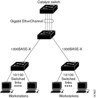
An EtherChannel consists of individual Ethernet links bundled into a single logical link.
The EtherChannel provides full-duplex bandwidth up to 8 Gb/s (Gigabit EtherChannel) or 80 Gb/s (10-Gigabit EtherChannel) between your switch and another switch or host.
Each EtherChannel can consist of up to eight compatibly configured Ethernet ports.
The number of EtherChannels is limited to 128.
The LAN Base feature set supports up to 24 EtherChannels.
All ports in each EtherChannel must be configured as either Layer 2 or Layer 3 ports. The EtherChannel Layer 3 ports are made up of routed ports. Routed ports are physical ports configured to be in Layer 3 mode by using the no switchport interface configuration command.
Related Concepts
Related Tasks
EtherChannel Modes
You can configure an EtherChannel in one of these modes: Port Aggregation Protocol (PAgP), Link Aggregation Control Protocol (LACP), or On. Configure both ends of the EtherChannel in the same mode:
- When you configure one end of an EtherChannel in either PAgP or LACP mode, the system negotiates with the other end of the channel to determine which ports should become active. If the remote port cannot negotiate an EtherChannel, the local port is put into an independent state and continues to carry data traffic as would any other single link. The port configuration does not change, but the port does not participate in the EtherChannel.
- When you configure an EtherChannel in the on mode, no negotiations take place. The switch forces all compatible ports to become active in the EtherChannel. The other end of the channel (on the other switch) must also be configured in the on mode; otherwise, packet loss can occur.
Related Concepts
Related Tasks
EtherChannel on Switches
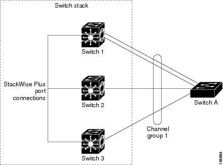
You can create an EtherChannel on a switch, on a single switch in the stack, or on multiple switches in the stack (known as cross-stack EtherChannel).
Related Concepts
Related Tasks
EtherChannel Link Failover
If a link within an EtherChannel fails, traffic previously carried over that failed link moves to the remaining links within the EtherChannel. If traps are enabled on the switch, a trap is sent for a failure that identifies the switch, the EtherChannel, and the failed link. Inbound broadcast and multicast packets on one link in an EtherChannel are blocked from returning on any other link of the EtherChannel.
Related Concepts
Related Tasks
Channel Groups and Port-Channel Interfaces
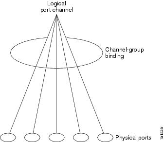
An EtherChannel comprises a channel group and a port-channel interface. The channel group binds physical ports to the port-channel interface. Configuration changes applied to the port-channel interface apply to all the physical ports bound together in the channel group.
Figure 4. Relationship of Physical Ports, Channel Group and Port-Channel Interface.The channel-group command binds the physical port and the port-channel interface together. Each EtherChannel has a port-channel logical interface numbered from 1 to 128. This port-channel interface number corresponds to the one specified with the channel-group interface configuration command.
- With Layer 2 ports, use the channel-group interface configuration command to dynamically create the port-channel interface. You also can use the interface port-channel port-channel-number global configuration command to manually create the port-channel interface, but then you must use the channel-group channel-group-number command to bind the logical interface to a physical port. The channel-group-number can be the same as the port-channel-number, or you can use a new number. If you use a new number, the channel-group command dynamically creates a new port channel.
- With Layer 3 ports, you should manually create the logical interface by using the interface port-channel global configuration command followed by the no switchport interface configuration command. You then manually assign an interface to the EtherChannel by using the channel-group interface configuration command.
- With Layer 3 ports, use the no switchport interface command to configure the interface as a Layer 3 interface, and then use the channel-group interface configuration command to dynamically create the port-channel interface.
Related Concepts
Port Aggregation Protocol
The Port Aggregation Protocol (PAgP) is a Cisco-proprietary protocol that can be run only on Cisco switches and on those switches licensed by vendors to support PAgP. PAgP facilitates the automatic creation of EtherChannels by exchanging PAgP packets between Ethernet ports. PAgP can be enabled on cross-stack EtherChannels.
By using PAgP, the switch or switch stack learns the identity of partners capable of supporting PAgP and the capabilities of each port. It then dynamically groups similarly configured ports (on a single switch in the stack) into a single logical link (channel or aggregate port). Similarly configured ports are grouped based on hardware, administrative, and port parameter constraints. For example, PAgP groups the ports with the same speed, duplex mode, native VLAN, VLAN range, and trunking status and type. After grouping the links into an EtherChannel, PAgP adds the group to the spanning tree as a single switch port.
PAgP Modes
PAgP modes specify whether a port can send PAgP packets, which start PAgP negotiations, or only respond to PAgP packets received.
Table 1 EtherChannel PAgP ModesMode
Description
auto
Places a port into a passive negotiating state, in which the port responds to PAgP packets it receives but does not start PAgP packet negotiation. This setting minimizes the transmission of PAgP packets.
desirable
Places a port into an active negotiating state, in which the port starts negotiations with other ports by sending PAgP packets. This mode is not supported when the EtherChannel members are from different switches in the switch stack (cross-stack EtherChannel).
Switch ports exchange PAgP packets only with partner ports configured in the auto or desirable modes. Ports configured in the on mode do not exchange PAgP packets.
Both the auto and desirable modes enable ports to negotiate with partner ports to form an EtherChannel based on criteria such as port speed. and for Layer 2 EtherChannels, based on trunk state and VLAN numbers.
Ports can form an EtherChannel when they are in different PAgP modes as long as the modes are compatible. For example:
- A port in the desirable mode can form an EtherChannel with another port that is in the desirable or auto mode.
- A port in the auto mode can form an EtherChannel with another port in the desirable mode.
A port in the auto mode cannot form an EtherChannel with another port that is also in the auto mode because neither port starts PAgP negotiation.
Related Concepts
Related Tasks
Silent Mode
If your switch is connected to a partner that is PAgP-capable, you can configure the switch port for nonsilent operation by using the non-silent keyword. If you do not specify non-silent with the auto or desirable mode, silent mode is assumed.
Use the silent mode when the switch is connected to a device that is not PAgP-capable and seldom, if ever, sends packets. An example of a silent partner is a file server or a packet analyzer that is not generating traffic. In this case, running PAgP on a physical port connected to a silent partner prevents that switch port from ever becoming operational. However, the silent setting allows PAgP to operate, to attach the port to a channel group, and to use the port for transmission.
Related Concepts
PAgP Learn Method and Priority
Network devices are classified as PAgP physical learners or aggregate-port learners. A device is a physical learner if it learns addresses by physical ports and directs transmissions based on that knowledge. A device is an aggregate-port learner if it learns addresses by aggregate (logical) ports. The learn method must be configured the same at both ends of the link.
When a device and its partner are both aggregate-port learners, they learn the address on the logical port-channel. The device sends packets to the source by using any of the ports in the EtherChannel. With aggregate-port learning, it is not important on which physical port the packet arrives.
PAgP cannot automatically detect when the partner device is a physical learner and when the local device is an aggregate-port learner. Therefore, you must manually set the learning method on the local device to learn addresses by physical ports. You also must set the load-distribution method to source-based distribution, so that any given source MAC address is always sent on the same physical port.
You also can configure a single port within the group for all transmissions and use other ports for hot-standby. The unused ports in the group can be swapped into operation in just a few seconds if the selected single port loses hardware-signal detection. You can configure which port is always selected for packet transmission by changing its priority with the pagp port-priority interface configuration command. The higher the priority, the more likely that the port will be selected.
Note
The switch supports address learning only on aggregate ports even though the physical-port keyword is provided in the CLI. The pagp learn-method command and the pagp port-priority command have no effect on the switch hardware, but they are required for PAgP interoperability with devices that only support address learning by physical ports, such as the Catalyst 1900 switch.
When the link partner of the switch is a physical learner, we recommend that you configure the switch as a physical-port learner by using the pagp learn-method physical-port interface configuration command. Set the load-distribution method based on the source MAC address by using the port-channel load-balance src-mac global configuration command. The switch then sends packets to the physcial learner using the same port in the EtherChannel from which it learned the source address. Only use the pagp learn-method command in this situation.
Related Concepts
Related Tasks
Related References
PAgP Interaction with Other Features
The Dynamic Trunking Protocol (DTP) and the Cisco Discovery Protocol (CDP) send and receive packets over the physical ports in the EtherChannel. Trunk ports send and receive PAgP protocol data units (PDUs) on the lowest numbered VLAN.
In Layer 2 EtherChannels, the first port in the channel that comes up provides its MAC address to the EtherChannel. If this port is removed from the bundle, one of the remaining ports in the bundle provides its MAC address to the EtherChannel. For Layer 3 EtherChannels, the MAC address is allocated by the active switch as soon as the interface is created (through the interface port-channel global configuration command).
PAgP sends and receives PAgP PDUs only from ports that are up and have PAgP enabled for the auto or desirable mode.
Link Aggregation Control Protocol
The LACP is defined in IEEE 802.3ad and enables Cisco switches to manage Ethernet channels between switches that conform to the IEEE 802.3ad protocol. LACP facilitates the automatic creation of EtherChannels by exchanging LACP packets between Ethernet ports.
By using LACP, the switch or switch stack learns the identity of partners capable of supporting LACP and the capabilities of each port. It then dynamically groups similarly configured ports into a single logical link (channel or aggregate port). Similarly configured ports are grouped based on hardware, administrative, and port parameter constraints. For example, LACP groups the ports with the same speed, duplex mode, native VLAN, VLAN range, and trunking status and type. After grouping the links into an EtherChannel, LACP adds the group to the spanning tree as a single switch port.
LACP Modes
LACP modes specify whether a port can send LACP packets or only receive LACP packets.
Table 2 EtherChannel LACP ModesMode
Description
active
Places a port into an active negotiating state in which the port starts negotiations with other ports by sending LACP packets.
passive
Places a port into a passive negotiating state in which the port responds to LACP packets that it receives, but does not start LACP packet negotiation. This setting minimizes the transmission of LACP packets.
Both the active and passive LACP modes enable ports to negotiate with partner ports to an EtherChannel based on criteria such as port speed, and for Layer 2 EtherChannels, based on trunk state and VLAN numbers.
Ports can form an EtherChannel when they are in different LACP modes as long as the modes are compatible. For example:
Related Concepts
Related Tasks
LACP and Link Redundancy
LACP port-channel operation, bandwidth availability, and link redundancy can be further refined with the LACP port-channel min-links and the LACP max-bundle features.
The LACP port-channel min-links feature:
- Configures the minimum number of ports that must be linked up and bundled in the LACP port channel.
- Prevents a low-bandwidth LACP port channel from becoming active.
- Causes an LACP port channel to become inactive if there are too few active members ports to supply the required minimum bandwidth.
The LACP max-bundle feature:
Related Tasks
Related References
LACP Interaction with Other Features
The DTP and the CDP send and receive packets over the physical ports in the EtherChannel. Trunk ports send and receive LACP PDUs on the lowest numbered VLAN.
In Layer 2 EtherChannels, the first port in the channel that comes up provides its MAC address to the EtherChannel. If this port is removed from the bundle, one of the remaining ports in the bundle provides its MAC address to the EtherChannel. For Layer 3 EtherChannels, the MAC address is allocated by the active switch as soon as the interface is created through the interface port-channel global configuration command.
LACP sends and receives LACP PDUs only from ports that are up and have LACP enabled for the active or passive mode.
EtherChannel On Mode
EtherChannel on mode can be used to manually configure an EtherChannel. The on mode forces a port to join an EtherChannel without negotiations. The on mode can be useful if the remote device does not support PAgP or LACP. In the on mode, a usable EtherChannel exists only when the switches at both ends of the link are configured in the on mode.
Ports that are configured in the on mode in the same channel group must have compatible port characteristics, such as speed and duplex. Ports that are not compatible are suspended, even though they are configured in the on mode.
Caution
You should use care when using the on mode. This is a manual configuration, and ports on both ends of the EtherChannel must have the same configuration. If the group is misconfigured, packet loss or spanning-tree loops can occur.
Load-Balancing and Forwarding Methods
EtherChannel balances the traffic load across the links in a channel by reducing part of the binary pattern formed from the addresses in the frame to a numerical value that selects one of the links in the channel. You can specify one of several different load-balancing modes, including load distribution based on MAC addresses, IP addresses, source addresses, destination addresses, or both source and destination addresses. The selected mode applies to all EtherChannels configured on the switch.
You configure the load-balancing and forwarding method by using the port-channel load-balance and the port-channel load-balance extendedglobal configuration commands.
Related Concepts
Related Tasks
MAC Address Forwarding
With source-MAC address forwarding, when packets are forwarded to an EtherChannel, they are distributed across the ports in the channel based on the source-MAC address of the incoming packet. Therefore, to provide load-balancing, packets from different hosts use different ports in the channel, but packets from the same host use the same port in the channel.
With destination-MAC address forwarding, when packets are forwarded to an EtherChannel, they are distributed across the ports in the channel based on the destination host’s MAC address of the incoming packet. Therefore, packets to the same destination are forwarded over the same port, and packets to a different destination are sent on a different port in the channel.
With source-and-destination MAC address forwarding, when packets are forwarded to an EtherChannel, they are distributed across the ports in the channel based on both the source and destination MAC addresses. This forwarding method, a combination source-MAC and destination-MAC address forwarding methods of load distribution, can be used if it is not clear whether source-MAC or destination-MAC address forwarding is better suited on a particular switch. With source-and-destination MAC-address forwarding, packets sent from host A to host B, host A to host C, and host C to host B could all use different ports in the channel.
Related Concepts
Related Tasks
IP Address Forwarding
With source-IP address-based forwarding, packets are distributed across the ports in the EtherChannel based on the source-IP address of the incoming packet. To provide load balancing, packets from different IP addresses use different ports in the channel, and packets from the same IP address use the same port in the channel.
With destination-IP address-based forwarding, packets are distributed across the ports in the EtherChannel based on the destination-IP address of the incoming packet. To provide load balancing, packets from the same IP source address sent to different IP destination addresses could be sent on different ports in the channel. Packets sent from different source IP addresses to the same destination IP address are always sent on the same port in the channel.
With source-and-destination IP address-based forwarding, packets are distributed across the ports in the EtherChannel based on both the source and destination IP addresses of the incoming packet. This forwarding method, a combination of source-IP and destination-IP address-based forwarding, can be used if it is not clear whether source-IP or destination-IP address-based forwarding is better suited on a particular switch. In this method, packets sent from the IP address A to IP address B, from IP address A to IP address C, and from IP address C to IP address B could all use different ports in the channel.
Related Concepts
Related Tasks
Load-Balancing Advantages
Different load-balancing methods have different advantages, and the choice of a particular load-balancing method should be based on the position of the switch in the network and the kind of traffic that needs to be load-distributed.
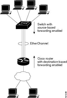
Figure 5. Load Distribution and Forwarding Methods. In the following figure, an EtherChannel of four workstations communicates with a router. Because the router is a single MAC-address device, source-based forwarding on the switch EtherChannel ensures that the switch uses all available bandwidth to the router. The router is configured for destination-based forwarding because the large number of workstations ensures that the traffic is evenly distributed from the router EtherChannel.Use the option that provides the greatest variety in your configuration. For example, if the traffic on a channel is going only to a single MAC address, using the destination-MAC address always chooses the same link in the channel. Using source addresses or IP addresses might result in better load-balancing.
Related Concepts
Related Tasks
EtherChannel and Switch Stacks
If a stack member that has ports participating in an EtherChannel fails or leaves the stack, the active switch removes the failed stack member switch ports from the EtherChannel. The remaining ports of the EtherChannel, if any, continue to provide connectivity.
When a switch is added to an existing stack, the new switch receives the running configuration from the active switch and updates itself with the EtherChannel-related stack configuration. The stack member also receives the operational information (the list of ports that are up and are members of a channel).
When two stacks merge that have EtherChannels configured between them, self-looped ports result. Spanning tree detects this condition and acts accordingly. Any PAgP or LACP configuration on a winning switch stack is not affected, but the PAgP or LACP configuration on the losing switch stack is lost after the stack reboots.
Switch Stack and PAgP
With PAgP, if the active switch fails or leaves the stack, the standby switch becomes the new active switch. A spanning-tree reconvergence is not triggered unless there is a change in the EtherChannel bandwidth. The new active switch synchronizes the configuration of the stack members to that of the active switch. The PAgP configuration is not affected after an active switch change unless the EtherChannel has ports residing on the old active switch.
Switch Stacks and LACP
With LACP, the system ID uses the stack MAC address from the active switch. When an active switch fails or leaves the stack and the standby switch becomes the new active switch change, the LACP system ID is unchanged. By default, the LACP configuration is not affected after the active switch changes.
Default EtherChannel Configuration
The default EtherChannel configuration is described in this table.
Table 3 Default EtherChannel ConfigurationFeature
Default Setting
Channel groups
None assigned.
Port-channel logical interface
None defined.
PAgP mode
No default.
PAgP learn method
Aggregate-port learning on all ports.
PAgP priority
128 on all ports.
LACP mode
No default.
LACP learn method
Aggregate-port learning on all ports.
LACP port priority
32768 on all ports.
LACP system priority
32768.
LACP system ID
LACP system priority and the switch or stack MAC address.
Load-balancing
Load distribution on the switch is based on the source-MAC address of the incoming packet.
Related Concepts
Related Tasks
EtherChannel Configuration Guidelines
If improperly configured, some EtherChannel ports are automatically disabled to avoid network loops and other problems. Follow these guidelines to avoid configuration problems:
- Do not try to configure more than 128 EtherChannels on the switch or switch stack.
- Configure a PAgP EtherChannel with up to eight Ethernet ports of the same type.
- Configure a LACP EtherChannel with up to 16 Ethernet ports of the same type. Up to eight ports can be active, and up to eight ports can be in standby mode.
- Configure all ports in an EtherChannel to operate at the same speeds and duplex modes.
- Enable all ports in an EtherChannel. A port in an EtherChannel that is disabled by using the shutdown interface configuration command is treated as a link failure, and its traffic is transferred to one of the remaining ports in the EtherChannel.
- When a group is first created, all ports follow the parameters set for the first port to be added to the group. If you change the configuration of one of these parameters, you must also make the changes to all ports in the group:
- Do not configure a port to be a member of more than one EtherChannel group.
- Do not configure an EtherChannel in both the PAgP and LACP modes. EtherChannel groups running PAgP and LACP can coexist on the same switch or on different switches in the stack. Individual EtherChannel groups can run either PAgP or LACP, but they cannot interoperate.
- Do not configure a secure port as part of an EtherChannel or the reverse.
- Do not configure a port that is an active or a not-yet-active member of an EtherChannel as an IEEE 802.1x port. If you try to enable IEEE 802.1x on an EtherChannel port, an error message appears, and IEEE 802.1x is not enabled.
- If EtherChannels are configured on switch interfaces, remove the EtherChannel configuration from the interfaces before globally enabling IEEE 802.1x on a switch by using the dot1x system-auth-control global configuration command.
- If cross-stack EtherChannel is configured and the switch stack partitions, loops and forwarding issues can occur.
Related Concepts
Related Tasks
Layer 2 EtherChannel Configuration Guidelines
When configuring Layer 2 EtherChannels, follow these guidelines:
- Assign all ports in the EtherChannel to the same VLAN, or configure them as trunks. Ports with different native VLANs cannot form an EtherChannel.
- An EtherChannel supports the same allowed range of VLANs on all the ports in a trunking Layer 2 EtherChannel. If the allowed range of VLANs is not the same, the ports do not form an EtherChannel even when PAgP is set to the auto or desirable mode.
- Ports with different spanning-tree path costs can form an EtherChannel if they are otherwise compatibly configured. Setting different spanning-tree path costs does not, by itself, make ports incompatible for the formation of an EtherChannel.
Related Concepts
Related Tasks
How to Configure EtherChannels
After you configure an EtherChannel, configuration changes applied to the port-channel interface apply to all the physical ports assigned to the port-channel interface, and configuration changes applied to the physical port affect only the port where you apply the configuration.
- Configuring Layer 2 EtherChannels (CLI)
- Configuring Layer 3 EtherChannels (CLI)
- Configuring EtherChannel Load-Balancing (CLI)
- Configuring EtherChannel Extended Load-Balancing (CLI)
- Configuring the PAgP Learn Method and Priority (CLI)
- Configuring LACP Hot-Standby Ports
Configuring Layer 2 EtherChannels (CLI)
SUMMARY STEPSYou configure Layer 2 EtherChannels by assigning ports to a channel group with the channel-group interface configuration command. This command automatically creates the port-channel logical interface.
2. interface interface-id
3. switchport mode {access | trunk}
4. switchport access vlan vlan-id
5. channel-group channel-group-number mode {auto [non-silent] | desirable [non-silent ] | on } | { active | passive}
6. end
DETAILED STEPSConfiguring Layer 3 EtherChannels (CLI)
SUMMARY STEPSBeginning in privileged EXEC mode, follow these steps to assign an Ethernet port to a Layer 3 EtherChannel. This procedure is required.
1. configure terminal
2. interface interface-id
3. no ip address
4. no switchport
5. channel-group channel-group-number mode { auto [ non-silent ] | desirable [ non-silent ] | on } | { active | passive }
6. end
DETAILED STEPSConfiguring EtherChannel Load-Balancing (CLI)
SUMMARY STEPSYou can configure EtherChannel load-balancing to use one of several different forwarding methods.
This task is optional.
1. configure terminal
2. port-channel load-balance { dst-ip | dst-mac | dst-mixed-ip-port | dst-port | extended [dst-ip | dst-mac | dst-port | ipv6-label | l3-proto | src-ip | src-mac | src-port ] | src-dst-ip | src-dst-mac src-dst-mixed-ip-port src-dst-portsrc-ip | src-mac | src-mixed-ip-port | src-port}
3. end
DETAILED STEPSConfiguring EtherChannel Extended Load-Balancing (CLI)
SUMMARY STEPSConfigure EtherChannel extended load-balancing when you want to use a combination of load-balancing methods.
This task is optional.
1. configure terminal
2. port-channel load-balance extended [ dst-ip | dst-mac dst-port | ipv6-label | l3-proto | src-ip | src-mac | src-port ]
3. end
DETAILED STEPSConfiguring the PAgP Learn Method and Priority (CLI)
SUMMARY STEPS
1. configure terminal
2. interface interface-id
3. pagp learn-method physical-port
4. pagp port-priority priority
5. end
DETAILED STEPSRelated Concepts
Related References
Configuring LACP Hot-Standby Ports
When LACP is enabled, the software, by default, tries to configure the maximum number of LACP-compatible ports in a channel, up to a maximum of 16 ports. Only eight LACP links can be active at one time; the remaining eight links are placed in hot-standby mode. If one of the active links becomes inactive, a link that is in the hot-standby mode becomes active in its place.
You can override the default behavior by specifying the maximum number of active ports in a channel, in which case, the remaining ports become hot-standby ports. For example, if you specify a maximum of five ports in a channel, up to 11 ports become hot-standby ports.
If you configure more than eight links for an EtherChannel group, the software automatically decides which of the hot-standby ports to make active based on the LACP priority. To every link between systems that operate LACP, the software assigns a unique priority made up of these elements (in priority order):
In priority comparisons, numerically lower values have higher priority. The priority decides which ports should be put in standby mode when there is a hardware limitation that prevents all compatible ports from aggregating.
Determining which ports are active and which are hot standby is a two-step procedure. First the system with a numerically lower system priority and system ID is placed in charge of the decision. Next, that system decides which ports are active and which are hot standby, based on its values for port priority and port number. The port priority and port number values for the other system are not used.
You can change the default values of the LACP system priority and the LACP port priority to affect how the software selects active and standby links.
- Configuring the LACP Max Bundle Feature (CLI)
- Configuring the Port Channel Min-Links Feature (CLI)
- Configuring the LACP System Priority (CLI)
- Configuring the LACP Port Priority (CLI)
Configuring the LACP Max Bundle Feature (CLI)
SUMMARY STEPSWhen you specify the maximum number of bundled LACP ports allowed in a port channel, the remaining ports in the port channel are designated as hot-standby ports.
Beginning in privileged EXEC mode, follow these steps to configure the maximum number of LACP ports in a port channel. This procedure is optional.
1. configure terminal
2. interface port-channel channel-number
3. lacp max-bundle max-bundle-number
DETAILED STEPSRelated Concepts
Related References
Configuring the Port Channel Min-Links Feature (CLI)
SUMMARY STEPSYou can specify the minimum number of active ports that must be in the link-up state and bundled in an EtherChannel for the port channel interface to transition to the link-up state.
Beginning in privileged EXEC mode, follow these steps to configure the minimum number of links that are required for a port channel. This procedure is optional.
1. configure terminal
2. interface port-channel channel-number
3. port-channel min-links min-links-number
DETAILED STEPSConfiguring the LACP System Priority (CLI)
SUMMARY STEPSYou can configure the system priority for all the EtherChannels that are enabled for LACP by using the lacp system-priority global configuration command. You cannot configure a system priority for each LACP-configured channel. By changing this value from the default, you can affect how the software selects active and standby links.
You can use the show etherchannel summary privileged EXEC command to see which ports are in the hot-standby mode (denoted with an H port-state flag).
Beginning in privileged EXEC mode, follow these steps to configure the LACP system priority. This procedure is optional.
1. configure terminal
2. lacp system-priority priority
3. end
DETAILED STEPSRelated Concepts
Related References
Configuring the LACP Port Priority (CLI)
SUMMARY STEPSBy default, all ports use the same port priority. If the local system has a lower value for the system priority and the system ID than the remote system, you can affect which of the hot-standby links become active first by changing the port priority of LACP EtherChannel ports to a lower value than the default. The hot-standby ports that have lower port numbers become active in the channel first. You can use the show etherchannel summary privileged EXEC command to see which ports are in the hot-standby mode (denoted with an H port-state flag).
Note
If LACP is not able to aggregate all the ports that are compatible (for example, the remote system might have more restrictive hardware limitations), all the ports that cannot be actively included in the EtherChannel are put in the hot-standby state and are used only if one of the channeled ports fails.
Beginning in privileged EXEC mode, follow these steps to configure the LACP port priority. This procedure is optional.
1. configure terminal
2. interface interface-id
3. lacp port-priority priority
4. end
DETAILED STEPSRelated Concepts
Related References
Monitoring EtherChannel, PAgP, and LACP Status
You can display EtherChannel, PAgP, and LACP status using the commands listed in this table.
Table 4 Commands for Monitoring EtherChannel, PAgP, and LACP StatusCommand
Description
clear lacp { channel-group-number counters | counters }
Clears LACP channel-group information and traffic counters.
clear pagp { channel-group-number counters | counters }
Clears PAgP channel-group information and traffic counters.
show etherchannel [ channel-group-number { detail | port | port-channel | protocol | summary }] [ detail | load-balance | port | port-channel | protocol | summary ]
Displays EtherChannel information in a brief, detailed, and one-line summary form. Also displays the load-balance or frame-distribution scheme, port, port-channel, and protocol information.
show pagp [ channel-group-number ] { counters | internal | neighbor }
Displays PAgP information such as traffic information, the internal PAgP configuration, and neighbor information.
show pagp [ channel-group-number ] dual-active
Displays the dual-active detection status.
show lacp [ channel-group-number ] { counters | internal | neighbor | sys-id}
Displays LACP information such as traffic information, the internal LACP configuration, and neighbor information.
show running-config
Verifies your configuration entries.
show etherchannel load-balance
Displays the load balance or frame distribution scheme among ports in the port channel.
Related Concepts
Configuration Examples for Configuring EtherChannels
- Configuring Layer 2 EtherChannels: Examples
- Configuring Layer 3 EtherChannels: Examples
- Configuring LACP Hot-Standby Ports: Example
Configuring Layer 2 EtherChannels: Examples
This example shows how to configure an EtherChannel on a single switch in the stack. It assigns two ports as static-access ports in VLAN 10 to channel 5 with the PAgP mode desirable:
		Switch# configure terminal
		Switch(config)# interface range gigabitethernet2/0/1 -2
		Switch(config-if-range)# switchport mode access
		Switch(config-if-range)# switchport access vlan 10
		Switch(config-if-range)# channel-group 5 mode desirable non-silent
		Switch(config-if-range)# end
This example shows how to configure an EtherChannel on a single switch in the stack. It assigns two ports as static-access ports in VLAN 10 to channel 5 with the LACP mode active:
		Switch# configure terminal
		Switch(config)# interface range gigabitethernet2/0/1 -2
		Switch(config-if-range)# switchport mode access
		Switch(config-if-range)# switchport access vlan 10
		Switch(config-if-range)# channel-group 5 mode active
		Switch(config-if-range)# end
This example shows how to configure a cross-stack EtherChannel. It uses LACP passive mode and assigns two ports on stack member 1 and one port on stack member 2 as static-access ports in VLAN 10 to channel 5:
		Switch# configure terminal
		Switch(config)# interface range gigabitethernet2/0/4 -5
		Switch(config-if-range)# switchport mode access
		Switch(config-if-range)# switchport access vlan 10
		Switch(config-if-range)# channel-group 5 mode passive
		Switch(config-if-range)# exit
		Switch(config)# interface gigabitethernet3/0/3
		Switch(config-if)# switchport mode access
		Switch(config-if)# switchport access vlan 10
		Switch(config-if)# channel-group 5 mode passive
		Switch(config-if)# exit
Configuring Layer 3 EtherChannels: Examples
This example shows how to configure a Layer 3 EtherChannel. It assigns two ports to channel 5 with the LACP mode active:
		Switch# configure terminal
		Switch(config)# interface range gigabitethernet2/0/1 -2
		Switch(config-if-range)# no ip address
		Switch(config-if-range)# no switchport
		Switch(config-if-range)# channel-group 5 mode active
		Switch(config-if-range)# end
This example shows how to configure a cross-stack Layer 3 EtherChannel. It assigns two ports on stack member 2 and one port on stack member 3 to channel 7 using LACP active mode:
		Switch# configure terminal
		Switch(config)# interface range gigabitethernet2/0/4 -5
		Switch(config-if-range)# no ip address
		Switch(config-if-range)# no switchport
		Switch(config-if-range)# channel-group 7 mode active
		Switch(config-if-range)# exit
		Switch(config)# interface gigabitethernet3/0/3
		Switch(config-if)# no ip address
		Switch(config-if)# no switchport
		Switch(config-if)# channel-group 7 mode active
		Switch(config-if)# exit
Configuring LACP Hot-Standby Ports: Example
This example shows how to configure an Etherchannel (port channel 2) that will be active when there are at least three active ports, will comprise up to seven active ports and the remaining ports (up to nine) as hot-standby ports :
		Switch# configure terminal
		Switch(config)# interface port-channel 2
		Switch(config-if)# port-channel min-links 3
  Switch(config-if)# lacp max-bundle 7
Related Concepts
Additional References for EtherChannels
Error Message Decoder
Description Link To help you research and resolve system error messages in this release, use the Error Message Decoder tool.
https://www.cisco.com/cgi-bin/Support/Errordecoder/index.cgi
MIBs
Technical Assistance
Description Link The Cisco Support website provides extensive online resources, including documentation and tools for troubleshooting and resolving technical issues with Cisco products and technologies.
To receive security and technical information about your products, you can subscribe to various services, such as the Product Alert Tool (accessed from Field Notices), the Cisco Technical Services Newsletter, and Really Simple Syndication (RSS) Feeds.
Access to most tools on the Cisco Support website requires a Cisco.com user ID and password.