Feedback
Contents
Intra Sub Domain Mobility
Layer 2 Roaming
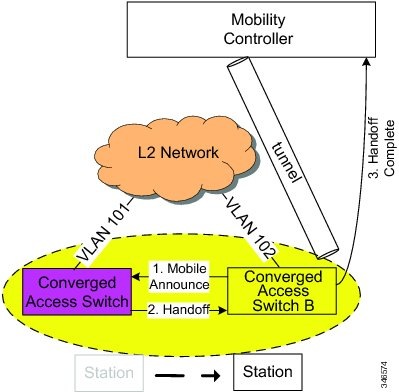
This section explains the bridging concept where a station roams across the switch.
When a station roams across switches and if its SSID and VLAN mapping matches, it is called a layer 2 roam.
In the illustration, when a station roams across switches the target switch has access to the station's VLAN or subnet. When the handoff is complete, the MC is informed through the Handoff Complete message. The new switchbecomes the new point of presence for the station, and is responsible for advertising serviceability for the station directly.
Layer 3 Roaming
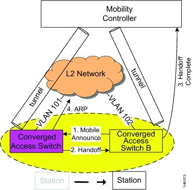
Layer 3 roaming happens when a station roams to an switch where the same VLAN or subnet is not available.
Point of Presence at Access Switch
The original switch becomes the anchor switch of the station. The new switch to which the station roams becomes the foreign switch of the station. In this scenario, the tunneling is direct between the foreign switch and the anchor switch.
In case of intra SPG, the tunneling is direct.
In case of inter SPG, the tunneling is directed through the MC.
The illustration above explains the data path for for native stations and roamed stations.
- For native stations, the point of presence and the point of attachment is the same, Switch A.
- For an L3 roamed clients, the point of presence remains at the last switch with which the station was associated and where the station's subnet was available, while point of attachment moves to the client to which it has has roamed.
The following events explains the Layer 3 roam with Anchor Switch as the point of presence:
- A station joins the network by associating to the AP on Switch A and is provided with an IP address from a subnet available on it. Its traffic is natively bridged at the switch and no tunneling is required. Switch A is both the point of presence and point of attachment for the station.
- When the station roams to Switch B where the same subnet is not available, the information is provided in the handoff process.
- In inter SPG roaming within the same sub-domain, when the handoff is complete, the MC is informed via the Handoff Complete message, and includes an indicator that traffic arriving on a tunnel from Switch B needs to be transmitted on a tunnel to Switch A.
- In intra SPG within the same sub-domain, when the handoff is complete, the tunneling does not have to go through MC. The tunneling is direct between Switch B and Switch A.
- The anchor switch, Switch A, continues to be the station's point of presence and Switch B becomes the point of attachment.
When the roamed station sends traffic to a wired host, the traffic is tunneled to the MTE, and from there to the Switch A. In the same way, since the point of presence is at Switch A, the traffic from the wired host comes to Switch A, and is tunneled first to the MTE, and from there to the foreign Switch B.