Feedback
Contents
- Configuring DHCP
- Finding Feature Information
- Information About DHCP
- DHCP Server
- DHCP Relay Agent
- DHCP Snooping
- Option-82 Data Insertion
- Cisco IOS DHCP Server Database
- DHCP Snooping Binding Database
- DHCP Snooping and Switch Stacks
- How to Configure DHCP Features
- Default DHCP Snooping Configuration
- DHCP Snooping Configuration Guidelines
- Configuring the DHCP Server
- DHCP Server and Switch Stacks
- Configuring the DHCP Relay Agent
- Specifying the Packet Forwarding Address
- Prerequisites for Configuring DHCP Snooping and Option 82
- Enabling DHCP Snooping and Option 82
- Enabling the Cisco IOS DHCP Server Database
- Monitoring DHCP Snooping Information
- Configuring DHCP Server Port-Based Address Allocation
- Information About Configuring DHCP Server Port-Based Address Allocation
- Default Port-Based Address Allocation Configuration
- Port-Based Address Allocation Configuration Guidelines
- Enabling the DHCP Snooping Binding Database Agent
- Enabling DHCP Server Port-Based Address Allocation
- Monitoring DHCP Server Port-Based Address Allocation
Configuring DHCP
Finding Feature Information
Your software release may not support all the features documented in this module. For the latest feature information and caveats, see the release notes for your platform and software release.
Use Cisco Feature Navigator to find information about platform support and Cisco software image support. To access Cisco Feature Navigator, go to http://www.cisco.com/go/cfn. An account on Cisco.com is not required.
Related References
Information About DHCP
DHCP Server
The DHCP server assigns IP addresses from specified address pools on a switch or router to DHCP clients and manages them. If the DHCP server cannot give the DHCP client the requested configuration parameters from its database, it forwards the request to one or more secondary DHCP servers defined by the network administrator.
DHCP Relay Agent
A DHCP relay agent is a Layer 3 device that forwards DHCP packets between clients and servers. Relay agents forward requests and replies between clients and servers when they are not on the same physical subnet. Relay agent forwarding is different from the normal Layer 2 forwarding, in which IP datagrams are switched transparently between networks. Relay agents receive DHCP messages and generate new DHCP messages to send on output interfaces.
DHCP Snooping
DHCP snooping is a DHCP security feature that provides network security by filtering untrusted DHCP messages and by building and maintaining a DHCP snooping binding database, also referred to as a DHCP snooping binding table.
DHCP snooping acts like a firewall between untrusted hosts and DHCP servers. You use DHCP snooping to differentiate between untrusted interfaces connected to the end user and trusted interfaces connected to the DHCP server or another switch.
NoteFor DHCP snooping to function properly, all DHCP servers must be connected to the switch through trusted interfaces.
An untrusted DHCP message is a message that is received through an untrusted interface. By default, the switch considers all interfaces untrusted. So, the switch must be configured to trust some interfaces to use DHCP Snooping. When you use DHCP snooping in a service-provider environment, an untrusted message is sent from a device that is not in the service-provider network, such as a customer’s switch. Messages from unknown devices are untrusted because they can be sources of traffic attacks.
The DHCP snooping binding database has the MAC address, the IP address, the lease time, the binding type, the VLAN number, and the interface information that corresponds to the local untrusted interfaces of a switch. It does not have information regarding hosts interconnected with a trusted interface.
In a service-provider network, an example of an interface you might configure as trusted is one connected to a port on a device in the same network. An example of an untrusted interface is one that is connected to an untrusted interface in the network or to an interface on a device that is not in the network.
When a switch receives a packet on an untrusted interface and the interface belongs to a VLAN in which DHCP snooping is enabled, the switch compares the source MAC address and the DHCP client hardware address. If the addresses match (the default), the switch forwards the packet. If the addresses do not match, the switch drops the packet.
The switch drops a DHCP packet when one of these situations occurs:
- A packet from a DHCP server, such as a DHCPOFFER, DHCPACK, DHCPNAK, or DHCPLEASEQUERY packet, is received from outside the network or firewall.
- A packet is received on an untrusted interface, and the source MAC address and the DHCP client hardware address do not match.
- The switch receives a DHCPRELEASE or DHCPDECLINE broadcast message that has a MAC address in the DHCP snooping binding database, but the interface information in the binding database does not match the interface on which the message was received.
- A DHCP relay agent forwards a DHCP packet that includes a relay-agent IP address that is not 0.0.0.0, or the relay agent forwards a packet that includes option-82 information to an untrusted port.
If the switch is an aggregation switch supporting DHCP snooping and is connected to an edge switch that is inserting DHCP option-82 information, the switch drops packets with option-82 information when packets are received on an untrusted interface. If DHCP snooping is enabled and packets are received on a trusted port, the aggregation switch does not learn the DHCP snooping bindings for connected devices and cannot build a complete DHCP snooping binding database.
When an aggregation switch can be connected to an edge switch through an untrusted interface and you enter the ip dhcp snooping information option allow-untrusted global configuration command, the aggregation switch accepts packets with option-82 information from the edge switch. The aggregation switch learns the bindings for hosts connected through an untrusted switch interface. The DHCP security features, such as dynamic ARP inspection or IP source guard, can still be enabled on the aggregation switch while the switch receives packets with option-82 information on untrusted input interfaces to which hosts are connected. The port on the edge switch that connects to the aggregation switch must be configured as a trusted interface.
Related References
Option-82 Data Insertion
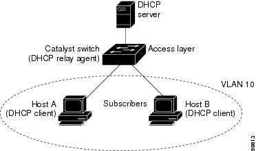
In residential, metropolitan Ethernet-access environments, DHCP can centrally manage the IP address assignments for a large number of subscribers. When the DHCP option-82 feature is enabled on the switch, a subscriber device is identified by the switch port through which it connects to the network (in addition to its MAC address). Multiple hosts on the subscriber LAN can be connected to the same port on the access switch and are uniquely identified.
NoteThe DHCP option-82 feature is supported only when DHCP snooping is globally enabled on the VLANs to which subscriber devices using option-82 are assigned.
The following illustration shows a metropolitan Ethernet network in which a centralized DHCP server assigns IP addresses to subscribers connected to the switch at the access layer. Because the DHCP clients and their associated DHCP server do not reside on the same IP network or subnet, a DHCP relay agent (the Catalyst switch) is configured with a helper address to enable broadcast forwarding and to transfer DHCP messages between the clients and the server.
When you enable the DHCP snooping information option 82 on the switch, the following sequence of events occurs:
- The host (DHCP client) generates a DHCP request and broadcasts it on the network.
- When the switch receives the DHCP request, it adds the option-82 information in the packet. By default, the remote-ID suboption is the switch MAC address, and the circuit-ID suboption is the port identifier, vlan-mod-port, from which the packet is received.You can configure the remote ID and circuit ID.
- If the IP address of the relay agent is configured, the switch adds this IP address in the DHCP packet.
- The switch forwards the DHCP request that includes the option-82 field to the DHCP server.
- The DHCP server receives the packet. If the server is option-82-capable, it can use the remote ID, the circuit ID, or both to assign IP addresses and implement policies, such as restricting the number of IP addresses that can be assigned to a single remote ID or circuit ID. Then the DHCP server echoes the option-82 field in the DHCP reply.
- The DHCP server unicasts the reply to the switch if the request was relayed to the server by the switch. The switch verifies that it originally inserted the option-82 data by inspecting the remote ID and possibly the circuit ID fields. The switch removes the option-82 field and forwards the packet to the switch port that connects to the DHCP client that sent the DHCP request.
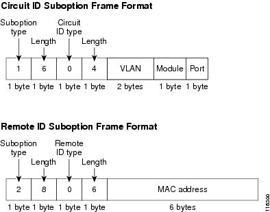
In the default suboption configuration, when the described sequence of events occurs, the values in these fields do not change (see the illustration,Suboption Packet Formats):
In the port field of the circuit ID suboption, the port numbers start at 3. For example, on a Catalyst 3850 switch with 24 10/100/1000 ports and four small form-factor pluggable (SFP) module slots, port 3 is the Gigabit Ethernet 1/0/1 port, port 4 is the Gigabit Ethernet 1/0/2 port, and so forth. Port 27 is the SFP module slot Gigabit Ethernet1/0/25, and so forth.
The illustration, Suboption Packet Formats. shows the packet formats for the remote-ID suboption and the circuit-ID suboption when the default suboption configuration is used. For the circuit-ID suboption, the module number corresponds to the switch number in the stack. The switch uses the packet formats when you globally enable DHCP snooping and enter the ip dhcp snooping information option global configuration command.
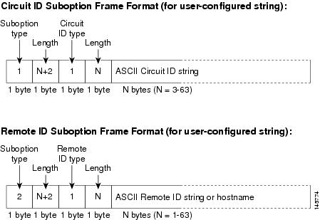
The illustration, User-Configured Suboption Packet Formats, shows the packet formats for user-configured remote-ID and circuit-ID suboptions The switch uses these packet formats when DHCP snooping is globally enabled and when the ip dhcp snooping information option format remote-id global configuration command and theip dhcp snooping vlan information option format-type circuit-id string interface configuration command are entered.
The values for these fields in the packets change from the default values when you configure the remote-ID and circuit-ID suboptions:
Cisco IOS DHCP Server Database
During the DHCP-based autoconfiguration process, the designated DHCP server uses the Cisco IOS DHCP server database. It has IP addresses, address bindings, and configuration parameters, such as the boot file.
An address binding is a mapping between an IP address and a MAC address of a host in the Cisco IOS DHCP server database. You can manually assign the client IP address, or the DHCP server can allocate an IP address from a DHCP address pool. For more information about manual and automatic address bindings, see the “Configuring DHCP” chapter of the Cisco IOS IP Configuration Guide, Release 12.4.
For procedures to enable and configure the Cisco IOS DHCP server database, see the “DHCP Configuration Task List” section in the “Configuring DHCP” chapter of the Cisco IOS IP Configuration Guide, Release 12.4.
DHCP Snooping Binding Database
When DHCP snooping is enabled, the switch uses the DHCP snooping binding database to store information about untrusted interfaces. The database can have up to 64,000 bindings.
Each database entry (binding) has an IP address, an associated MAC address, the lease time (in hexadecimal format), the interface to which the binding applies, and the VLAN to which the interface belongs. The database agent stores the bindings in a file at a configured location. At the end of each entry is a checksum that accounts for all the bytes from the start of the file through all the bytes associated with the entry. Each entry is 72 bytes, followed by a space and then the checksum value.
To keep the bindings when the switch reloads, you must use the DHCP snooping database agent. If the agent is disabled, dynamic ARP inspection or IP source guard is enabled, and the DHCP snooping binding database has dynamic bindings, the switch loses its connectivity. If the agent is disabled and only DHCP snooping is enabled, the switch does not lose its connectivity, but DHCP snooping might not prevent DHCP spoofing attacks.
When reloading, the switch reads the binding file to build the DHCP snooping binding database. The switch updates the file when the database changes.
When a switch learns of new bindings or when it loses bindings, the switch immediately updates the entries in the database. The switch also updates the entries in the binding file. The frequency at which the file is updated is based on a configurable delay, and the updates are batched. If the file is not updated in a specified time (set by the write-delay and abort-timeout values), the update stops.
This is the format of the file with bindings:
<initial-checksum>
TYPE DHCP-SNOOPING
VERSION 1
BEGIN
<entry-1> <checksum-1>
<entry-2> <checksum-1-2>
...
...
<entry-n> <checksum-1-2-..-n>
END
Each entry in the file is tagged with a checksum value that the switch uses to verify the entries when it reads the file. The initial-checksum entry on the first line distinguishes entries associated with the latest file update from entries associated with a previous file update.
This is an example of a binding file:
2bb4c2a1
TYPE DHCP-SNOOPING
VERSION 1
BEGIN
192.1.168.1 3 0003.47d8.c91f 2BB6488E Gi1/0/4 21ae5fbb
192.1.168.3 3 0003.44d6.c52f 2BB648EB Gi1/0/4 1bdb223f
192.1.168.2 3 0003.47d9.c8f1 2BB648AB Gi1/0/4 584a38f0
END
When the switch starts and the calculated checksum value equals the stored checksum value, the switch reads entries from the binding file and adds the bindings to its DHCP snooping binding database. The switch ignores an entry when one of these situations occurs:
- The switch reads the entry and the calculated checksum value does not equal the stored checksum value. The entry and the ones following it are ignored.
- An entry has an expired lease time (the switch might not remove a binding entry when the lease time expires).
- The interface in the entry no longer exists on the system.
- The interface is a routed interface or a DHCP snooping-trusted interface.
DHCP Snooping and Switch Stacks
DHCP snooping is managed on the stack master. When a new switch joins the stack, the switch receives the DHCP snooping configuration from the stack master. When a member leaves the stack, all DHCP snooping address bindings associated with the switch age out.
All snooping statistics are generated on the stack master. If a new stack master is elected, the statistics counters reset.
When a stack merge occurs, all DHCP snooping bindings in the stack master are lost if it is no longer the stack master. With a stack partition, the existing stack master is unchanged, and the bindings belonging to the partitioned switches age out. The new master of the partitioned stack begins processing the new incoming DHCP packets.
How to Configure DHCP Features
Default DHCP Snooping Configuration
Table 1 Default DHCP Configuration Enabled in Cisco IOS software, requires configuration1
Enabled2
DHCP snooping option to accept packets on untrusted input interfaces3
Enabled in Cisco IOS software, requires configuration.
Note The switch gets network addresses and configuration parameters only from a device configured as a DHCP server.
Enabled in Cisco IOS software, requires configuration. This feature is operational only when a destination is configured.
1 The switch responds to DHCP requests only if it is configured as a DHCP server.2 The switch relays DHCP packets only if the IP address of the DHCP server is configured on the SVI of the DHCP client.3 Use this feature when the switch is an aggregation switch that receives packets with option-82 information from an edge switch.DHCP Snooping Configuration Guidelines
- If a switch port is connected to a DHCP server, configure a port as trusted by entering the ip dhcp snooping trust interface configuration command.
- If a switch port is connected to a DHCP client, configure a port as untrusted by entering the no ip dhcp snooping trust interface configuration command.
- You can display DHCP snooping statistics by entering the show ip dhcp snooping statistics user EXEC command, and you can clear the snooping statistics counters by entering the clear ip dhcp snooping statistics privileged EXEC command.
DHCP Server and Switch Stacks
The DHCP binding database is managed on the stack master. When a new stack master is assigned, the new master downloads the saved binding database from the TFTP server. If the stack master fails, all unsaved bindings are lost. The IP addresses associated with the lost bindings are released. You should configure an automatic backup by using the ip dhcp database url [timeout seconds | write-delay seconds] global configuration command.
When a stack merge occurs, the stack master that becomes a stack member loses all of the DHCP lease bindings. With a stack partition, the new master in the partition acts as a new DHCP server without any of the existing DHCP lease bindings.
Configuring the DHCP Relay Agent
SUMMARY STEPS
DETAILED STEPSWhat to Do Next
Command or Action Purpose See the “Configuring DHCP” section of the “IP Addressing and Services” section of the Cisco IOS IP Configuration Guide, Release 12.4 for these procedures:
Specifying the Packet Forwarding Address
SUMMARY STEPSIf the DHCP server and the DHCP clients are on different networks or subnets, you must configure the switch with the ip helper-address address interface configuration command. The general rule is to configure the command on the Layer 3 interface closest to the client. The address used in the ip helper-address command can be a specific DHCP server IP address, or it can be the network address if other DHCP servers are on the destination network segment. Using the network address enables any DHCP server to respond to requests.
Beginning in privileged EXEC mode, follow these steps to specify the packet forwarding address:
3. ip address ip-address subnet-mask
6. interface range port-range or interface interface-id
DETAILED STEPSPrerequisites for Configuring DHCP Snooping and Option 82
The prerequisites for DHCP Snooping and Option 82 are as follows:
- Before configuring the DHCP snooping information option on your switch, be sure to configure the device that is acting as the DHCP server. You must specify the IP addresses that the DHCP server can assign or exclude, or you must configure DHCP options for these devices.
- For DHCP snooping to function properly, all DHCP servers must be connected to the switch through trusted interfaces.
- Before configuring the DHCP relay agent on your switch, make sure to configure the device that is acting as the DHCP server. You must specify the IP addresses that the DHCP server can assign or exclude, configure DHCP options for devices, or set up the DHCP database agent.
- The following prerequisites apply to DHCP snooping binding database configuration:
- Because both NVRAM and the flash memory have limited storage capacity, we recommend that you store the binding file on a TFTP server.
- For network-based URLs (such as TFTP and FTP), you must create an empty file at the configured URL before the switch can write bindings to the binding file at that URL. See the documentation for your TFTP server to determine whether you must first create an empty file on the server; some TFTP servers cannot be configured this way.
- To ensure that the lease time in the database is accurate, we recommend that you enable and configure Network Time Protocol (NTP).
- If NTP is configured, the switch writes binding changes to the binding file only when the switch system clock is synchronized with NTP.
- If you want the switch to respond to DHCP requests, it must be configured as a DHCP server.
- If you want the switch to relay DHCP packets, the IP address of the DHCP server must be configured on the switch virtual interface (SVI) of the DHCP client.
- To use the DHCP snooping option of accepting packets on untrusted inputs, the switch must be an aggregation switch that receives packets with option-82 information from an edge switch.
- You must configure the switch to use the Cisco IOS DHCP server binding database to use it for DHCP snooping.
- You must configure a destination on the DHCP snooping binding database to use the switch for DHCP snooping.
- For DHCP snooping to function properly, all DHCP servers must be connected to the switch through trusted interfaces. In a service-provider network, a trusted interface is connected to a port on a device in the same network.
- You must globally enable DHCP snooping on the switch.
- Before globally enabling DHCP snooping on the switch, make sure that the devices acting as the DHCP server and the DHCP relay agent are configured and enabled.
NoteDo not enable Dynamic Host Configuration Protocol (DHCP) snooping on RSPAN VLANs. If DHCP snooping is enabled on RSPAN VLANs, DHCP packets might not reach the RSPAN destination port.
Related Concepts
Enabling DHCP Snooping and Option 82
SUMMARY STEPS
3. ip dhcp snooping vlan vlan-range []
4. ip dhcp snooping information option
5. ip dhcp snooping information option format remote-id [string ASCII-string | hostname]
6. ip dhcp snooping information option allow-untrusted
8. ip dhcp snooping vlan vlan information option format-type circuit-id [override] string ASCII-string
10. ip dhcp snooping limit rate rate
DETAILED STEPSMonitoring DHCP Snooping Information
Table 2 Commands for Displaying DHCP Information Displays only the dynamically configured bindings in the DHCP snooping binding database, also referred to as a binding table.
Displays the DHCP snooping binding database status and statistics.
Displays the DHCP snooping statistics in summary or detail form.
Configuring DHCP Server Port-Based Address Allocation
Information About Configuring DHCP Server Port-Based Address Allocation
DHCP server port-based address allocation is a feature that enables DHCP to maintain the same IP address on an Ethernet switch port regardless of the attached device client identifier or client hardware address.
When Ethernet switches are deployed in the network, they offer connectivity to the directly connected devices. In some environments, such as on a factory floor, if a device fails, the replacement device must be working immediately in the existing network. With the current DHCP implementation, there is no guarantee that DHCP would offer the same IP address to the replacement device. Control, monitoring, and other software expect a stable IP address associated with each device. If a device is replaced, the address assignment should remain stable even though the DHCP client has changed.
When configured, the DHCP server port-based address allocation feature ensures that the same IP address is always offered to the same connected port even as the client identifier or client hardware address changes in the DHCP messages received on that port. The DHCP protocol recognizes DHCP clients by the client identifier option in the DHCP packet. Clients that do not include the client identifier option are identified by the client hardware address. When you configure this feature, the port name of the interface overrides the client identifier or hardware address and the actual point of connection, the switch port, becomes the client identifier.
In all cases, by connecting the Ethernet cable to the same port, the same IP address is allocated through DHCP to the attached device.
The DHCP server port-based address allocation feature is only supported on a Cisco IOS DHCP server and not a third-party server.
Port-Based Address Allocation Configuration Guidelines
- By default, DHCP server port-based address allocation is disabled.
- To restrict assignments from the DHCP pool to preconfigured reservations (unreserved addresses are not offered to the client and other clients are not served by the pool), you can enter the reserved-only DHCP pool configuration command.
Enabling the DHCP Snooping Binding Database Agent
SUMMARY STEPSBeginning in privileged EXEC mode, follow these steps to enable and configure the DHCP snooping binding database agent on the switch:
2. ip dhcp snooping database {flash[number]:/filename | ftp://user:password@host/filename | http://[[username:password]@]{hostname | host-ip}[/directory] /image-name.tar | rcp://user@host/filename}| tftp://host/filename
3. ip dhcp snooping database timeout seconds
4. ip dhcp snooping database write-delay seconds
6. ip dhcp snooping binding mac-address vlan vlan-id ip-address interface interface-id expiry seconds
DETAILED STEPS
Command or Action Purpose
Step 1 configure terminal
Example:Switch# configure terminalStep 2 ip dhcp snooping database {flash[number]:/filename | ftp://user:password@host/filename | http://[[username:password]@]{hostname | host-ip}[/directory] /image-name.tar | rcp://user@host/filename}| tftp://host/filename
Example:Switch(config)# ip dhcp snooping database tftp://10.90.90.90/snooping-rp2Specifies the URL for the database agent or the binding file by using one of these forms:
- flash[number]:/filename (Optional) Use the number parameter to specify the stack member number of the stack master. The range for number is 1 to 9.
- ftp://user:password@host/filename
- http://[[username:password]@]{hostname | host-ip}[/directory] /image-name.tar
- rcp://user@host/filename
- tftp://host/filename
Step 3 ip dhcp snooping database timeout seconds
Example:Switch(config)# ip dhcp snooping database timeout 300Specifies (in seconds) how long to wait for the database transfer process to finish before stopping the process.
The default is 300 seconds. The range is 0 to 86400. Use 0 to define an infinite duration, which means to continue trying the transfer indefinitely.
Step 4 ip dhcp snooping database write-delay seconds
Example:Switch(config)# ip dhcp snooping database write-delay 15Specifies the duration for which the transfer should be delayed after the binding database changes. The range is from 15 to 86400 seconds. The default is 300 seconds (5 minutes).
Step 5 end
Example:Switch(config)# endStep 6 ip dhcp snooping binding mac-address vlan vlan-id ip-address interface interface-id expiry seconds
Example:Switch# ip dhcp snooping binding 0001.1234.1234 vlan 1 172.20.50.5 interface gi1/1 expiry 1000(Optional) Adds binding entries to the DHCP snooping binding database. The vlan-id range is from 1 to 4904. The seconds range is from 1 to 4294967295.
Enter this command for each entry that you add.
Use this command when you are testing or debugging the switch.
Enabling DHCP Server Port-Based Address Allocation
SUMMARY STEPSBeginning in privileged EXEC mode, follow these steps to globally enable port-based address allocation and to automatically generate a subscriber identifier on an interface.
2. ip dhcp use subscriber-id client-id
3. ip dhcp subscriber-id interface-name
DETAILED STEPS
Command or Action Purpose
Step 1 configure terminal
Example:Switch# configure terminalStep 2 ip dhcp use subscriber-id client-id
Example:Switch(config)# ip dhcp use subscriber-id client-idConfigures the DHCP server to globally use the subscriber identifier as the client identifier on all incoming DHCP messages.
Step 3 ip dhcp subscriber-id interface-name
Example:Switch(config)# ip dhcp subscriber-id interface-nameAutomatically generates a subscriber identifier based on the short name of the interface.
A subscriber identifier configured on a specific interface takes precedence over this command.
Step 4 interface interface-id
Example:Switch(config)# interface gigabitethernet1/0/1Specifies the interface to be configured, and enter interface configuration mode.
Step 5 ip dhcp server use subscriber-id client-id
Example:Switch(config-if)# ip dhcp server use subscriber-id client-idConfigures the DHCP server to use the subscriber identifier as the client identifier on all incoming DHCP messages on the interface.
Step 6 end
Example:Switch(config)# end