A client VLAN must be mapped to the WLAN configured on the switch
Restrictions for IPv6 WLAN Security
RADIUS Server Support
If multiple RADIUS servers are configured for redundancy, the user database must be identical in all the servers for the backup to work properly.
Radius ACS Support
You must configure RADIUS on both your Cisco Secure Access Control Server (ACS) and your switch
RADIUS is supported on Cisco Secure ACS version 3.2 and later releases.
Information About IPv6 WLAN Security
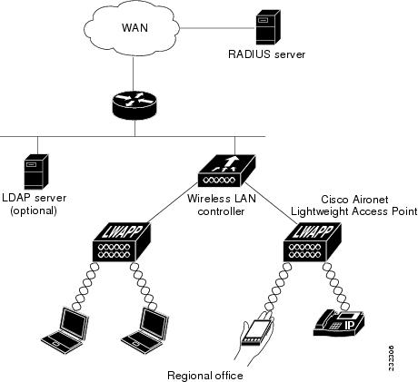
Information About RADIUS
Remote Authentication Dial-In User Service (RADIUS) is a client/server protocol that provides centralized security for users attempting to gain management access to a network. It serves as a back-end database similar to Local EAP and provides authentication and accounting services.
Authentication—The process of verifying users when they attempt to log into the switch
Users must enter a valid username and password for the switch to authenticate users to the RADIUS server. If multiple databases are configured, then specify the sequence in which the backend database must be tried.
Accounting— The process of recording user actions and changes.
Whenever a user successfully executes an action, the RADIUS accounting server logs the changed attributes, the user ID of the person who made the change, the remote host where the user is logged in, the date and time when the command was executed, the authorization level of the user, and a description of the action performed and the values provided. If the RADIUS accounting server is unreachable, the users can continue their sessions uninterrupted.
User Datagram Protocol— RADIUS uses User Datagram Protocol (UDP) for its transport. It maintains a database and listens on UDP port 1812 for incoming authentication requests and UDP port 1813 for incoming accounting requests. The switch, which requires access control, acts as the client and requests AAA services from the server. The traffic between the switch and the server is encrypted by an algorithm defined in the protocol and a shared secret key configured on both devices.
Configures multiple RADIUS accounting and authentication servers. For example, you can have one central RADIUS authentication server but several RADIUS accounting servers in different regions. If you configure multiple servers of the same type and the first one fails or becomes unreachable, the controller automatically tries the second one, then the third one if necessary, and so on.
When RADIUS method is configured for the WLAN, the switch will use the RADIUS method configured for the WLAN. When the WLAN is configured to use local EAP, the RADIUS method configured on the WLAN points to Local. The WLAN must also be configured with the name of the local EAP profile to use.
If no RADIUS method is configured in the WLAN, the switch will use the default RADIUS method defined in global mode.
Information About Local EAP
Local EAP is an authentication method that allows users and wireless clients to be authenticated locally. It is designed for use in remote offices that maintain connectivity to wireless clients when the back-end system is disrupted or the external authentication server goes down. When you enable local EAP, the switch serves as the authentication server and the local user database, which removes dependence on an external authentication server. Local EAP retrieves user credentials from the local user database or the LDAP back-end database to authenticate users. Local EAP supports LEAP, EAP-FAST, EAP-TLS, PEAPv0/MSCHAPv2, and PEAPv1/GTC authentication between the controller and wireless clients.
Note
The LDAP back-end database supports these local EAP methods: EAP-TLS, EAP-FAST/GTC, and PEAPv1/GTC. LEAP, EAP-FAST/MSCHAPv2, and PEAPv0. MSCHAPv2 is supported only if the LDAP server is set up to return a clear-text password.
Note
Switch support Local EAP authentication against external LDAP databases such as Microsoft Active Directory and Novell’s eDirectory. For more information about configuring the controller for Local EAP authentication against Novell’s eDirectory, see the Configure Unified Wireless Network for Authentication Against Novell's eDirectory Database whitepaper.
5.aaa authentication dot1x method_list group wcm_rad
6.dot1x system-auth-control
7.aaa session-idcommon
DETAILED STEPS
Command or Action
Purpose
Step 1
configureterminal
Example:
Switch# configure terminal
Enters global command mode.
Step 2
aaa new-model
Example:
Switch(config)#aaa new-model
Creates a AAA authentication model.
Step 3
aaa group server radius wcm_rad
Example:
Switch(config)# aaa group server radius wcm_rad
Switch(config-sg-radius)#
Creates an radius server-group.
Step 4
server <ip address>auth-port1812acct-port1813
Example:
Switch(config-sg-radius)# server One auth-port 1812 acct-port 1813
Switch(config-sg-radius)# server Two auth-port 1812 acct-port 1813
Switch(config-sg-radius)# server Three auth-port 1812 acct-port 1813
Adds servers to the radius group created in Step 3. Configures the UDP port for RADIUS accounting server and authentication server.
Step 5
aaa authentication dot1x method_list group wcm_rad
Example:
Switch(config)# aaa authentication dot1x method_list group wcm_rad
Maps the method list to the radius group.
Step 6
dot1x system-auth-control
Example:
Switch(config)# dot1x system-auth-control
Enables the system authorization control for the radius group.
Step 7
aaa session-idcommon
Example:
Switch(config)# aaa session-id common
Ensures that all session IDs information sent out, from the radius group, for a given call are identical.
Switch# configure terminal
Switch(config)# aaa new-model
Switch(config)# aaa group server radius wcm_rad
Switch(config-sg-radius)# server One auth-port 1812 acct-port 1813
Switch(config-sg-radius)# server Two auth-port 1812 acct-port 1813
Switch(config-sg-radius)# server Three auth-port 1812 acct-port 1813
Switch(config)# aaa authentication dot1x method_list group wcm_rad
Switch(config)# dot1x system-auth-control
Switch(config)# aaa session-id common
Switch(config)#
Creating a Client VLAN
SUMMARY STEPS
1.configureterminal
2.vlan 137
3.exit
4.interface vlan 137
5.ip address 10.7.137.10 255.255.255.0
6.ipv6 address 2001:db8::30:1/64
7.end
DETAILED STEPS
Command or Action
Purpose
Step 1
configureterminal
Example:
Switch# configure terminal
Enters global command mode.
Step 2
vlan 137
Example:
Switch(config)# vlan 137
Creates a VLAN and associate it to the interface.
Step 3
exit
Example:
Switch (config-vlan)# exit
Exits from the VLAN mode.
Step 4
interface vlan 137
Example:
Switch (config)# interface vlan 137
Assigns a VLAN to an interface.
Step 5
ip address 10.7.137.10 255.255.255.0
Example:
Switch(config-if)# ip address 10.7.137.10 255.255.255.0
Assigns an IPv4 address to the VLAN interface.
Step 6
ipv6 address 2001:db8::30:1/64
Example:
Switch(config-if)# ipv6 address 2001:db8::30:1/64
Assigns an IPv6 address to the VLAN interface.
Step 7
end
Example:
Switch(config)# end
Returns to privileged EXEC mode. Alternatively, you can also press Ctrl-z to exit global configuration mode.

 Feedback