Feedback
Contents
- Configuring Ethernet Management Port
- Finding Feature Information
- Prerequisites for Ethernet Management Ports
- Information about the Ethernet Management Port
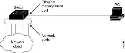
- Ethernet Management Port Direct Connection to a Switch
- Ethernet Management Port Connection to Stack Switches using a Hub
- Ethernet Management Port and Routing
- Supported Features on the Ethernet Management Port
- How to Configure the Ethernet Management Port
- Disabling and Enabling the Ethernet Management Port
- Additional References
Configuring Ethernet Management Port
This module contains the following sections:
- Finding Feature Information
- Prerequisites for Ethernet Management Ports
- Information about the Ethernet Management Port
- How to Configure the Ethernet Management Port
- Additional References
Finding Feature Information
Your software release may not support all the features documented in this module. For the latest feature information and caveats, see the release notes for your platform and software release.
Use Cisco Feature Navigator to find information about platform support and Cisco software image support. To access Cisco Feature Navigator, go to http://www.cisco.com/go/cfn. An account on Cisco.com is not required.
Related References
Information about the Ethernet Management Port
The Ethernet management port, also referred to as the Gi0/0 or GigabitEthernet0/0 port, is a VRF (VPN routing/forwarding) interface to which you can connect a PC. You can use the Ethernet management port instead of the switch console port for network management. When managing a switch stack, connect the PC to the Ethernet management port on a stack member.
- Ethernet Management Port Direct Connection to a Switch
- Ethernet Management Port Connection to Stack Switches using a Hub
- Ethernet Management Port and Routing
- Supported Features on the Ethernet Management Port
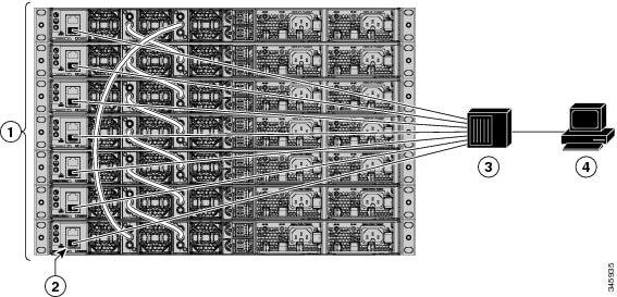
Ethernet Management Port Connection to Stack Switches using a Hub
In a stack with only stack switches, all the Ethernet management ports on the stack members are connected to a hub to which the PC is connected. The active link is from the Ethernet management port on the through the hub, to the PC. If the active switch fails and a new active switch is elected, the active link is now from the Ethernet management port on the new active switch to the PC.
Ethernet Management Port and Routing
By default, the Ethernet management port is enabled. The switch cannot route packets from the Ethernet management port to a network port, and the reverse. Even though the Ethernet management port does not support routing, you may need to enable routing protocols on the port.
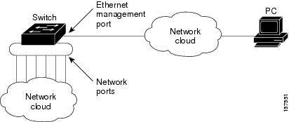
Figure 3. Network Example with Routing Protocols Enabled. In the following figure, you must enable routing protocols on the Ethernet management port when the PC is multiple hops away from the switch and the packets must pass through multiple Layer 3 devices to reach the PC.In the above figure , if the Ethernet management port and the network ports are associated with the same routing process, the routes are propagated as follows:
- The routes from the Ethernet management port are propagated through the network ports to the network.
- The routes from the network ports are propagated through the Ethernet management port to the network.
Because routing is not supported between the Ethernet management port and the network ports, traffic between these ports cannot be sent or received. If this happens, data packet loops occur between the ports, which disrupt the switch and network operation. To prevent the loops, configure route filters to avoid routes between the Ethernet management port and the network ports.
Supported Features on the Ethernet Management Port
The Ethernet management port supports these features:
- Express Setup (only in switch stacks)
- Network Assistant
- Telnet with passwords
- TFTP
- Secure Shell (SSH)
- DHCP-based autoconfiguration
- SMNP (only the ENTITY-MIB and the IF-MIB)
- IP ping
- Interface features
- Cisco Discovery Protocol (CDP)
- DHCP relay agent
- IPv4 and IPv6 access control lists (ACLs)
- Routing protocols
Caution
Before enabling a feature on the Ethernet management port, make sure that the feature is supported. If you try to configure an unsupported feature on the Ethernet Management port, the feature might not work properly, and the switch might fail.
How to Configure the Ethernet Management Port
Disabling and Enabling the Ethernet Management Port
SUMMARY STEPS
1. configure terminal
2. interface gigabitethernet0/0
3. shutdown
4. no shutdown
5. exit
6. show interfaces gigabitethernet0/0
DETAILED STEPS
Proceed to manage or configure your switch using the Ethernet management port. Refer to the Catalyst 2960-X Switch Network Management Configuration Guide.
Additional References
MIBs
Technical Assistance
Description Link The Cisco Support website provides extensive online resources, including documentation and tools for troubleshooting and resolving technical issues with Cisco products and technologies.
To receive security and technical information about your products, you can subscribe to various services, such as the Product Alert Tool (accessed from Field Notices), the Cisco Technical Services Newsletter, and Really Simple Syndication (RSS) Feeds.
Access to most tools on the Cisco Support website requires a Cisco.com user ID and password.