Feedback
Contents
- Configuring IGMP
- Finding Feature Information
- Restrictions for Configuring IGMP
- Information About IGMP
- IP Multicast Group Addresses
- IGMP Versions
- IGMP Version 1
- IGMP Version 2
- IGMP Version 3
- IGMPv3 Host Signalling
- IGMP Snooping
- Joining a Multicast Group
- Leaving a Multicast Group
- Immediate Leave
- IGMP Configurable-Leave Timer
- IGMP Report Suppression
- IGMP Snooping and Switch Stacks
- IGMP Filtering and Throttling Overview
- Default IGMP Configuration
- Default IGMP Snooping Configuration
- Default IGMP Filtering and Throttling Configuration
- How to Configure IGMP
- Configuring the Switch as a Member of a Group
- Controlling Access to IP Multicast Group
- Modifying the IGMP Host-Query Message Interval
- Changing the IGMP Query Timeout for IGMPv2
- Changing the Maximum Query Response Time for IGMPv2
- Configuring the Switch as a Statically Connected Member
- Configuring IGMP Profiles
- Applying IGMP Profiles
- Setting the Maximum Number of IGMP Groups
- Configuring the IGMP Throttling Action
- How to Configure IGMP Snooping
- Enabling IGMP Snooping on a Switch
- Enabling IGMP Snooping on a VLAN Interface
- Setting the Snooping Method
- Configuring a Multicast Router Port
- Configuring a Host Statically to Join a Group
- Enabling IGMP Immediate Leave
- Configuring the IGMP Leave Timer
- Configuring the IGMP Robustness-Variable
- Configuring the IGMP Last Member Query Count
- Configuring TCN-Related Commands
- Controlling the Multicast Flooding Time After a TCN Event
- Recovering from Flood Mode
- Disabling Multicast Flooding During a TCN Event
- Configuring the IGMP Snooping Querier
- Disabling IGMP Report Suppression
- Monitoring IGMP
- Displaying IGMP Snooping Information
- Displaying IGMP Filtering and Throttling Configuration
- Configuration Examples for IGMP
- Example: Configuring the Switch as a Member of a Multicast Group
- Example: Controlling Access to Multicast Groups
- Examples: Configuring IGMP Snooping
- Examples: Configuring Filtering and Throttling
- Example: Interface Configuration as a Routed Port
- Example: Interface Configuration as an SVI
- Where to Go Next for IGMP
- Additional References
- Feature Information for IGMP
Configuring IGMP
- Finding Feature Information
- Restrictions for Configuring IGMP
- Information About IGMP
- How to Configure IGMP
- Monitoring IGMP
- Configuration Examples for IGMP
- Where to Go Next for IGMP
- Additional References
- Feature Information for IGMP
Finding Feature Information
Your software release may not support all the features documented in this module. For the latest feature information and caveats, see the release notes for your platform and software release.
Use Cisco Feature Navigator to find information about platform support and Cisco software image support. To access Cisco Feature Navigator, go to http://www.cisco.com/go/cfn. An account on Cisco.com is not required.
Related References
Restrictions for Configuring IGMP
The following are the restrictions for configuring IGMP:
- The switch supports IGMP Versions 1, 2 , and 3.
NoteFor IGMP Version 3, only IGMP Version 3 BISS (Basic IGMPv3 Snooping Support) is supported.
- IGMP Version 3 uses new membership report messages that might not be correctly recognized by older IGMP snooping switches.
- IGMP filtering and throttling is not supported under the WLAN.
Information About IGMP
To participate in IP multicasting, multicast hosts, routers, and multilayer switches must have the Internet Group Management Protocol (IGMP) operating. This protocol defines the querier and host roles:
- A querier is a network device that sends query messages to discover which network devices are members of a given multicast group.
- A host is a receiver that sends report messages (in response to query messages) to inform a querier of a host membership.
A set of queriers and hosts that receive multicast data streams from the same source is called a multicast group. Queriers and hosts use IGMP messages to join and leave multicast groups.
Any host, regardless of whether it is a member of a group, can send to a group. However, only the members of a group receive the message. Membership in a multicast group is dynamic; hosts can join and leave at any time. There is no restriction on the location or number of members in a multicast group. A host can be a member of more than one multicast group at a time. How active a multicast group is and what members it has can vary from group to group and from time to time. A multicast group can be active for a long time, or it can be very short-lived. Membership in a group can constantly change.
IP Multicast Group Addresses
IP multicast traffic uses group addresses, which are class D addresses. The high-order bits of a Class D address are 1110. Therefore, host group addresses can be in the range 224.0.0.0 through 239.255.255.255. Multicast addresses in the range 224.0.0.0 to 224.0.0.255 are reserved for use by routing protocols and other network control traffic. The address 224.0.0.0 is guaranteed not to be assigned to any group.
IGMP packets are sent using these IP multicast group addresses:
- IGMP general queries are destined to the address 224.0.0.1 (all systems on a subnet).
- IGMP group-specific queries are destined to the group IP address for which the switch is querying.
- IGMP group membership reports are destined to the group IP address for which the switch is reporting.
- IGMP Version 2 (IGMPv2) leave messages are destined to the address 224.0.0.2 (all multicast routers on a subnet). In some old host IP stacks, leave messages might be destined to the group IP address rather than to the all-routers address.
Related Tasks
Related References
IGMP Versions
The switch supports IGMP version 1, IGMP version 2, and IGMP version 3. These versions are interoperable on the switch. For example, if IGMP snooping is enabled and the querier's version is IGMPv2. and the switch receives an IGMPv3 report from a host, then the switch can forward the IGMPv3 report to the multicast router.
IGMP Version 1
IGMP version 1 (IGMPv1) primarily uses a query-response model that enables the multicast router and multilayer switch to find which multicast groups are active (have one or more hosts interested in a multicast group) on the local subnet. IGMPv1 has other processes that enable a host to join and leave a multicast group. For more information, see RFC 1112.
IGMP Version 2
IGMPv2 extends IGMP functionality by providing such features as the IGMP leave process to reduce leave latency, group-specific queries, and an explicit maximum query response time. IGMPv2 also adds the capability for routers to elect the IGMP querier without depending on the multicast protocol to perform this task. For more information, see RFC 2236.
NoteIGMP version 2 is the default version for the switch.
IGMP Version 3
The switch supports IGMP version 3. The following are considerations for the switch and IGMP version 3:
- An IGMPv3 switch supports Basic IGMPv3 Snooping Support (BISS), which includes support for the snooping features on IGMPv1 and IGMPv2 switches and for IGMPv3 membership report messages. BISS constrains the flooding of multicast traffic when your network includes IGMPv3 hosts. It constrains traffic to approximately the same set of ports as the IGMP snooping feature on IGMPv2 or IGMPv1 hosts.
- The switch supports IGMPv3 snooping based only on the destination multicast IP address. It does not support snooping based on a source IP address or proxy report.
- IGMPv3 join and leave messages are not supported on switches running IGMP filtering or Multicast VLAN registration (MVR).
- An IGMPv3 switch can receive messages from and forward messages to a device running the Source Specific Multicast (SSM) feature.
IGMPv3 Host Signalling
In IGMPv3, hosts signal membership to last hop routers of multicast groups. Hosts can signal group membership with filtering capabilities with respect to sources. A host can either signal that it wants to receive traffic from all sources sending to a group except for some specific sources (called exclude mode), or that it wants to receive traffic only from some specific sources sending to the group (called include mode).
IGMPv3 can operate with both Internet Standard Multicast (ISM) and Source Specific Multicast (SSM). In ISM, both exclude and include mode reports are applicable. In SSM, only include mode reports are accepted by the last-hop router. Exclude mode reports are ignored.
IGMP Snooping
Layer 2 switches can use IGMP snooping to constrain the flooding of multicast traffic by dynamically configuring Layer 2 interfaces so that multicast traffic is forwarded to only those interfaces associated with IP multicast devices. As the name implies, IGMP snooping requires the LAN switch to snoop on the IGMP transmissions between the host and the router and to keep track of multicast groups and member ports. When the switch receives an IGMP report from a host for a particular multicast group, the switch adds the host port number to the forwarding table entry; when it receives an IGMP Leave Group message from a host, it removes the host port from the table entry. It also periodically deletes entries if it does not receive IGMP membership reports from the multicast clients.
NoteFor more information on IP multicast and IGMP, see RFC 1112 and RFC 2236.
The multicast router (which could be a switch with the IP services feature set on the active switch) sends out periodic general queries to all VLANs. All hosts interested in this multicast traffic send join requests and are added to the forwarding table entry. The switch creates one entry per VLAN in the IGMP snooping IP multicast forwarding table for each group from which it receives an IGMP join request.
The switch supports IP multicast group-based bridging, instead of MAC-addressed based groups. With multicast MAC address-based groups, if an IP address being configured translates (aliases) to a previously configured MAC address or to any reserved multicast MAC addresses (in the range 224.0.0.xxx), the command fails. Because the switch uses IP multicast groups, there are no address aliasing issues.
The IP multicast groups learned through IGMP snooping are dynamic. However, you can statically configure multicast groups by using the ip igmp snooping vlanvlan-idstatic ip_address interface interface-id global configuration command. If you specify group membership for a multicast group address statically, your setting supersedes any automatic manipulation by IGMP snooping. Multicast group membership lists can consist of both user-defined and IGMP snooping-learned settings.
You can configure an IGMP snooping querier to support IGMP snooping in subnets without multicast interfaces because the multicast traffic does not need to be routed.
If a port spanning-tree, a port group, or a VLAN ID change occurs, the IGMP snooping-learned multicast groups from this port on the VLAN are deleted.
- Joining a Multicast Group
- Leaving a Multicast Group
- Immediate Leave
- IGMP Configurable-Leave Timer
- IGMP Report Suppression
- IGMP Snooping and Switch Stacks
- IGMP Filtering and Throttling Overview
Related Tasks
Related References
Joining a Multicast Group
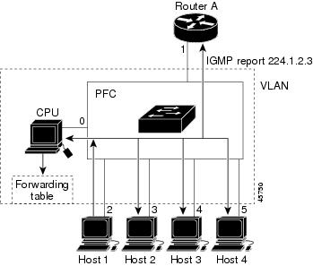
Figure 1. Initial IGMP Join Message.When a host connected to the switch wants to join an IP multicast group and it is an IGMP version 2 client, it sends an unsolicited IGMP join message, specifying the IP multicast group to join. Alternatively, when the switch receives a general query from the router, it forwards the query to all ports in the VLAN. IGMP version 1 or version 2 hosts wanting to join the multicast group respond by sending a join message to the switch. The switch CPU creates a multicast forwarding-table entry for the group if it is not already present. The CPU also adds the interface where the join message was received to the forwarding-table entry. The host associated with that interface receives multicast traffic for that multicast group.
Router A sends a general query to the switch, which forwards the query to ports 2 through 5, which are all members of the same VLAN. Host 1 wants to join multicast group 224.1.2.3 and multicasts an IGMP membership report (IGMP join message) to the group. The switch CPU uses the information in the IGMP report to set up a forwarding-table entry that includes the port numbers connected to Host 1 and to the router.
The switch hardware can distinguish IGMP information packets from other packets for the multicast group. The information in the table tells the switching engine to send frames addressed to the 224.1.2.3 multicast IP address that are not IGMP packets to the router and to the host that has joined the group.
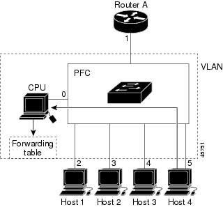
Figure 2. Second Host Joining a Multicast Group. If another host (for example, Host 4) sends an unsolicited IGMP join message for the same group, the CPU receives that message and adds the port number of Host 4 to the forwarding table. Because the forwarding table directs IGMP messages only to the CPU, the message is not flooded to other ports on the switch. Any known multicast traffic is forwarded to the group and not to the CPU.Related Tasks
Related References
Leaving a Multicast Group
The router sends periodic multicast general queries, and the switch forwards these queries through all ports in the VLAN. Interested hosts respond to the queries. If at least one host in the VLAN wants to receive multicast traffic, the router continues forwarding the multicast traffic to the VLAN. The switch forwards multicast group traffic only to those hosts listed in the forwarding table for that IP multicast group maintained by IGMP snooping.
When hosts want to leave a multicast group, they can silently leave, or they can send a leave message. When the switch receives a leave message from a host, it sends a group-specific query to learn if any other devices connected to that interface are interested in traffic for the specific multicast group. The switch then updates the forwarding table for that MAC group so that only those hosts interested in receiving multicast traffic for the group are listed in the forwarding table. If the router receives no reports from a VLAN, it removes the group for the VLAN from its IGMP cache.
Immediate Leave
The switch uses IGMP snooping Immediate Leave to remove from the forwarding table an interface that sends a leave message without the switch sending group-specific queries to the interface. The VLAN interface is pruned from the multicast tree for the multicast group specified in the original leave message. Immediate Leave ensures optimal bandwidth management for all hosts on a switched network, even when multiple multicast groups are simultaneously in use.
Immediate Leave is only supported on IGMP version 2 hosts. IGMP version 2 is the default version for the switch.
IGMP Configurable-Leave Timer
You can configure the time that the switch waits after sending a group-specific query to determine if hosts are still interested in a specific multicast group. The IGMP leave response time can be configured from 100 to 5000 milliseconds. The timer can be set either globally or on a per-VLAN basis. The VLAN configuration of the leave time overrides the global configuration.
Related Tasks
IGMP Report Suppression
NoteIGMP report suppression is supported only when the multicast query has IGMPv1 and IGMPv2 reports. This feature is not supported when the query includes IGMPv3 reports.
The switch uses IGMP report suppression to forward only one IGMP report per multicast router query to multicast devices. When IGMP router suppression is enabled (the default), the switch sends the first IGMP report from all hosts for a group to all the multicast routers. The switch does not send the remaining IGMP reports for the group to the multicast routers. This feature prevents duplicate reports from being sent to the multicast devices.
If the multicast router query includes requests only for IGMPv1 and IGMPv2 reports, the switch forwards only the first IGMPv1 or IGMPv2 report from all hosts for a group to all the multicast routers.
If the multicast router query also includes requests for IGMPv3 reports, the switch forwards all IGMPv1, IGMPv2, and IGMPv3 reports for a group to the multicast devices.
If you disable IGMP report suppression, all IGMP reports are forwarded to the multicast routers.
IGMP Snooping and Switch Stacks
IGMP snooping functions across the switch stack; that is, IGMP control information from one switch is distributed to all switches in the stack. Regardless of the stack member through which IGMP multicast data enters the stack, the data reaches the hosts that have registered for that group.
If a switch in the stack fails or is removed from the stack, only the members of the multicast group that are on that switch will not receive the multicast data. All other members of a multicast group on other switches in the stack continue to receive multicast data streams. However, multicast groups that are common for both Layer 2 and Layer 3 (IP multicast routing) might take longer to converge if the active switch is removed.
IGMP Filtering and Throttling Overview
In some environments, for example, metropolitan or multiple-dwelling unit (MDU) installations, you might want to control the set of multicast groups to which a user on a switch port can belong. You can control the distribution of multicast services, such as IP/TV, based on some type of subscription or service plan. You might also want to limit the number of multicast groups to which a user on a switch port can belong.
With the IGMP filtering feature, you can filter multicast joins on a per-port basis by configuring IP multicast profiles and associating them with individual switch ports. An IGMP profile can contain one or more multicast groups and specifies whether access to the group is permitted or denied. If an IGMP profile denying access to a multicast group is applied to a switch port, the IGMP join report requesting the stream of IP multicast traffic is dropped, and the port is not allowed to receive IP multicast traffic from that group. If the filtering action permits access to the multicast group, the IGMP report from the port is forwarded for normal processing. You can also set the maximum number of IGMP groups that a Layer 2 interface can join.
IGMP filtering controls only group-specific query and membership reports, including join and leave reports. It does not control general IGMP queries. IGMP filtering has no relationship with the function that directs the forwarding of IP multicast traffic. The filtering feature operates in the same manner whether CGMP or MVR is used to forward the multicast traffic.
IGMP filtering applies only to the dynamic learning of IP multicast group addresses, not static configuration.
With the IGMP throttling feature, you can set the maximum number of IGMP groups that a Layer 2 interface can join. If the maximum number of IGMP groups is set, the IGMP snooping forwarding table contains the maximum number of entries, and the interface receives an IGMP join report, you can configure an interface to drop the IGMP report or to replace the randomly selected multicast entry with the received IGMP report.
NoteIGMPv3 join and leave messages are not supported on switches running IGMP filtering.
Related Tasks
Default IGMP Configuration
Default IGMP Snooping Configuration
Default IGMP Filtering and Throttling Configuration
How to Configure IGMP
- Configuring the Switch as a Member of a Group
- Controlling Access to IP Multicast Group
- Modifying the IGMP Host-Query Message Interval
- Changing the IGMP Query Timeout for IGMPv2
- Changing the Maximum Query Response Time for IGMPv2
- Configuring the Switch as a Statically Connected Member
- Configuring IGMP Profiles
- Applying IGMP Profiles
- Setting the Maximum Number of IGMP Groups
- Configuring the IGMP Throttling Action
- How to Configure IGMP Snooping
Configuring the Switch as a Member of a Group
SUMMARY STEPSYou can configure the switch as a member of a multicast group and discover multicast reachability in a network. If all the multicast-capable routers and multilayer switches that you administer are members of a multicast group, pinging that group causes all these devices to respond. The devices respond to ICMP echo-request packets addressed to a group of which they are members. Another example is the multicast trace-route tools provided in the software.
CautionPerforming this procedure might impact the CPU performance because the CPU will receive all data traffic for the group address.
DETAILED STEPS
Command or Action Purpose
Step 1 configure terminal
Example:Switch# configure terminalStep 2 interface interface-id
Example:Switch(config)# interface gigabitethernet 1/0/1Specifies the Layer 3 interface on which you want to enable multicast routing, and enters interface configuration mode.
The specified interface must be one of the following:
- A routed port—A physical port that has been configured as a Layer 3 port by entering the no switchport interface configuration command. You will also need to enable IP PIM sparse-dense-mode on the interface, and join the interface as a statically connected member to an IGMP static group. For a configuration example, see Example: Interface Configuration as a Routed Port
- An SVI—A VLAN interface created by using the interface vlan vlan-id global configuration command. You will also need to enable IP PIM sparse-dense-mode on the VLAN, join the VLAN as a statically connected member to an IGMP static group, and then enable IGMP snooping on the VLAN, the IGMP static group, and physical interface. For a configuration example, see Example: Interface Configuration as an SVI
Step 3 ip igmp join-group group-address
Example:Switch(config-if)# ip igmp join-group 225.2.2.2Configures the switch to join a multicast group.
By default, no group memberships are defined.
For group-address, specify the multicast IP address in dotted decimal notation.
Step 4 end
Example:Switch(config-if)# endStep 5 show ip igmp interface [interface-id]
Example:Switch# show ip igmp interfaceStep 6 copy running-config startup-config
Example:Switch# copy running-config startup-config
Controlling Access to IP Multicast Group
SUMMARY STEPSThe switch sends IGMP host-query messages to find which multicast groups have members on attached local networks. The switch then forwards to these group members all packets addressed to the multicast group. You can place a filter on each interface to restrict the multicast groups that hosts on the subnet serviced by the interface can join.
To limit the number of joins on the interface, configure the port for the filter which associates with the IGMP profile.
This procedure is optional.
2. ip igmp profile
3. permit
6. ip igmp filter filter_number
7. end
DETAILED STEPS
Command or Action Purpose
Step 1 configure terminal
Example:Switch# configure terminalStep 2 ip igmp profile
Example:Switch(config)# ip igmp profile 10 Switch(config-igmp-profile)# ?Enters an IGMP filter profile number from 1 to 4294967295.
For additional information about configuring IGMP filter profiles, see Configuring IGMP Profiles.
Step 3 permit
Example:Switch(config-igmp-profile)# permit 229.9.9.0Enters an IGMP profile configuration action. The following IGMP profile configuration actions are supported:
Step 4 exit
Example:Switch(config-igmp-profile)# exitStep 5 interface interface-id
Example:Switch(config)# interface gigabitethernet 1/0/1Specifies the interface to be configured, and enters interface configuration mode.
Step 6 ip igmp filter filter_number
Example:Switch(config-if)# ip igmp filter 10Specifies the IGMP filter profile number.
For additional information about applying IGMP filter profiles, see Applying IGMP Profiles.
Step 7 end
Example:Switch(config-igmp-profile)# endReturns to privileged EXEC mode.
Step 8 show ip igmp interface [interface-id]
Example:Switch# show ip igmp interfaceModifying the IGMP Host-Query Message Interval
SUMMARY STEPSThe switch periodically sends IGMP host-query messages to discover which multicast groups are present on attached networks. These messages are sent to the all-hosts multicast group (224.0.0.1) with a time-to-live (TTL) of 1. The switch sends host-query messages to refresh its knowledge of memberships present on the network. If, after some number of queries, the software discovers that no local hosts are members of a multicast group, the software stops forwarding multicast packets to the local network from remote origins for that group and sends a prune message upstream toward the source.
The switch elects a PIM designated router (DR) for the LAN (subnet). The DR is the router or multilayer switch with the highest IP address for IGMPv2. For IGMPv1, the DR is elected according to the multicast routing protocol that runs on the LAN. The designated router is responsible for sending IGMP host-query messages to all hosts on the LAN. In sparse mode, the designated router also sends PIM register and PIM join messages toward the RP router.
DETAILED STEPS
Command or Action Purpose
Step 1 configure terminal
Example:Switch# configure terminalStep 2 interface interface-id
Example:Switch(config)# interface gigabitethernet 1/0/1Specifies the Layer 3 interface on which you want to enable multicast routing, and enters interface configuration mode.
The specified interface must be one of the following:
- A routed port—A physical port that has been configured as a Layer 3 port by entering the no switchport interface configuration command. You will also need to enable IP PIM sparse-dense-mode on the interface, and join the interface as a statically connected member to an IGMP static group. For a configuration example, see Example: Interface Configuration as a Routed Port
- An SVI—A VLAN interface created by using the interface vlan vlan-id global configuration command. You will also need to enable IP PIM sparse-dense-mode on the VLAN, join the VLAN as a statically connected member to an IGMP static group, and then enable IGMP snooping on the VLAN, the IGMP static group, and physical interface. For a configuration example, see Example: Interface Configuration as an SVI
Step 3 ip igmp query-interval seconds
Example:Switch(config-if)# ip igmp query-interval 75Configures the frequency at which the designated router sends IGMP host-query messages.
By default, the designated router sends IGMP host-query messages every 60 seconds to keep the IGMP overhead very low on hosts and networks. The range is 1 to 65535.
Step 4 end
Example:Switch(config-if)# endStep 5 show ip igmp interface [interface-id]
Example:Switch# show ip igmp interfaceStep 6 copy running-config startup-config
Example:Switch# copy running-config startup-configChanging the IGMP Query Timeout for IGMPv2
SUMMARY STEPSIf you are using IGMPv2, you can specify the period of time before the switch takes over as the querier for the interface. By default, the switch waits twice the query interval controlled by the ip igmp query-interval interface configuration command. After that time, if the switch has received no queries, it becomes the querier.
DETAILED STEPS
Command or Action Purpose
Step 1 configure terminal
Example:Switch# configure terminalStep 2 interface interface-id
Example:Switch(config)# interface gigabitethernet 1/0/1Specifies the Layer 3 interface on which you want to enable multicast routing, and enters interface configuration mode.
The specified interface must be one of the following:
- A routed port—A physical port that has been configured as a Layer 3 port by entering the no switchport interface configuration command. You will also need to enable IP PIM sparse-dense-mode on the interface, and join the interface as a statically connected member to an IGMP static group. For a configuration example, see Example: Interface Configuration as a Routed Port
- An SVI—A VLAN interface created by using the interface vlan vlan-id global configuration command. You will also need to enable IP PIM sparse-dense-mode on the VLAN, join the VLAN as a statically connected member to an IGMP static group, and then enable IGMP snooping on the VLAN, the IGMP static group, and physical interface. For a configuration example, see Example: Interface Configuration as an SVI
Step 3 ip igmp querier-timeout seconds
Example:Switch(config-if)# ip igmp querier-timeout 120Specifies the IGMP query timeout.
The default is 60 seconds (twice the query interval). The range is 60 to 300.
Step 4 end
Example:Switch(config-if)# endStep 5 show ip igmp interface [interface-id]
Example:Switch# show ip igmp interfaceStep 6 copy running-config startup-config
Example:Switch# copy running-config startup-configChanging the Maximum Query Response Time for IGMPv2
SUMMARY STEPSIf you are using IGMPv2, you can change the maximum query response time advertised in IGMP queries. The maximum query response time enables the switch to quickly detect that there are no more directly connected group members on a LAN. Decreasing the value enables the switch to prune groups faster.
DETAILED STEPS
Command or Action Purpose
Step 1 configure terminal
Example:Switch# configure terminalStep 2 interface interface-id
Example:Switch(config)# interface gigabitethernet 1/0/1Specifies the Layer 3 interface on which you want to enable multicast routing, and enters interface configuration mode.
The specified interface must be one of the following:
- A routed port—A physical port that has been configured as a Layer 3 port by entering the no switchport interface configuration command. You will also need to enable IP PIM sparse-dense-mode on the interface, and join the interface as a statically connected member to an IGMP static group. For a configuration example, see Example: Interface Configuration as a Routed Port
- An SVI—A VLAN interface created by using the interface vlan vlan-id global configuration command. You will also need to enable IP PIM sparse-dense-mode on the VLAN, join the VLAN as a statically connected member to an IGMP static group, and then enable IGMP snooping on the VLAN, the IGMP static group, and physical interface. For a configuration example, see Example: Interface Configuration as an SVI
Step 3 ip igmp query-max-response-time seconds
Example:Switch(config-if)# ip igmp query-max-response-time 15Changes the maximum query response time advertised in IGMP queries.
Step 4 end
Example:Switch(config-if)# endStep 5 show ip igmp interface [interface-id]
Example:Switch# show ip igmp interfaceStep 6 copy running-config startup-config
Example:Switch# copy running-config startup-configConfiguring the Switch as a Statically Connected Member
SUMMARY STEPSAt various times, there is either no group member on a network segment or a host cannot report its group membership by using IGMP. However, you may want multicast traffic to be sent to that network segment. The following commands are used to pull multicast traffic down to a network segment:
- ip igmp join-group—The switch accepts the multicast packets in addition to forwarding them. Accepting the multicast packets prevents the switch from fast switching.
- ip igmp static-group—The switch does not accept the packets itself, but only forwards them. This method enables fast switching. The outgoing interface appears in the IGMP cache, but the switch itself is not a member, as evidenced by lack of an L (local) flag in the multicast route entry.
DETAILED STEPS
Command or Action Purpose
Step 1 configure terminal
Example:Switch# configure terminalStep 2 interface interface-id
Example:Switch(config)# interface gigabitethernet 1/0/1Specifies the Layer 3 interface on which you want to enable multicast routing, and enters interface configuration mode.
The specified interface must be one of the following:
- A routed port—A physical port that has been configured as a Layer 3 port by entering the no switchport interface configuration command. You will also need to enable IP PIM sparse-dense-mode on the interface, and join the interface as a statically connected member to an IGMP static group. For a configuration example, see Example: Interface Configuration as a Routed Port
- An SVI—A VLAN interface created by using the interface vlan vlan-id global configuration command. You will also need to enable IP PIM sparse-dense-mode on the VLAN, join the VLAN as a statically connected member to an IGMP static group, and then enable IGMP snooping on the VLAN, the IGMP static group, and physical interface. For a configuration example, see Example: Interface Configuration as an SVI
Step 3 ip igmp static-group group-address
Example:Switch(config-if)# ip igmp static-group 239.100.100.101Configures the switch as a statically connected member of a group.
Step 4 end
Example:Switch(config-if)# endStep 5 show ip igmp interface [interface-id]
Example:Switch# show ip igmp interface gigabitethernet 1/0/1Step 6 copy running-config startup-config
Example:Switch# copy running-config startup-configConfiguring IGMP Profiles
SUMMARY STEPSTo configure an IGMP profile, use the ip igmp profile global configuration command with a profile number to create an IGMP profile and to enter IGMP profile configuration mode. From this mode, you can specify the parameters of the IGMP profile to be used for filtering IGMP join requests from a port. When you are in IGMP profile configuration mode, you can create the profile by using these commands:
- deny—Specifies that matching addresses are denied; this is the default.
- exit—Exits from igmp-profile configuration mode.
- no—Negates a command or returns to its defaults.
- permit—Specifies that matching addresses are permitted.
- range—Specifies a range of IP addresses for the profile. You can enter a single IP address or a range with a start and an end address.
The default is for the switch to have no IGMP profiles configured. When a profile is configured, if neither the permit nor deny keyword is included, the default is to deny access to the range of IP addresses.
DETAILED STEPSApplying IGMP Profiles
SUMMARY STEPSTo control access as defined in an IGMP profile, use the ip igmp filter interface configuration command to apply the profile to the appropriate interfaces. You can apply IGMP profiles only to Layer 2 access ports; you cannot apply IGMP profiles to routed ports or SVIs. You cannot apply profiles to ports that belong to an EtherChannel port group. You can apply a profile to multiple interfaces, but each interface can have only one profile applied to it.
DETAILED STEPSSetting the Maximum Number of IGMP Groups
SUMMARY STEPSYou can set the maximum number of IGMP groups that a Layer 2 interface can join by using the ip igmp max-groups interface configuration command. Use the no form of this command to set the maximum back to the default, which is no limit.
This restriction can be applied to Layer 2 ports only; you cannot set a maximum number of IGMP groups on routed ports or SVIs. You also can use this command on a logical EtherChannel interface but cannot use it on ports that belong to an EtherChannel port group.
Beginning in privileged EXEC mode, follow these steps to set the maximum number of IGMP groups in the forwarding table:
DETAILED STEPSConfiguring the IGMP Throttling Action
SUMMARY STEPSAfter you set the maximum number of IGMP groups that a Layer 2 interface can join, you can configure an interface to replace the existing group with the new group for which the IGMP report was received by using the ip igmp max-groups action replace interface configuration command. Use the no form of this command to return to the default, which is to drop the IGMP join report.
Follow these guidelines when configuring the IGMP throttling action:
- This restriction can be applied only to Layer 2 ports. You can use this command on a logical EtherChannel interface but cannot use it on ports that belong to an EtherChannel port group.
- When the maximum group limitation is set to the default (no maximum), entering the ip igmp max-groups action {deny | replace} command has no effect.
- If you configure the throttling action and set the maximum group limitation after an interface has added multicast entries to the forwarding table, the forwarding-table entries are either aged out or removed, depending on the throttling action.
- If you configure the throttling action as deny, the entries that were previously in the forwarding table are not removed but are aged out. After these entries are aged out and the maximum number of entries is in the forwarding table, the switch drops the next IGMP report received on the interface.
- If you configure the throttling action as replace, the entries that were previously in the forwarding table are removed. When the maximum number of entries is in the forwarding table, the switch replaces a randomly selected entry with the received IGMP report. To prevent the switch from removing the forwarding-table entries, you can configure the IGMP throttling action before an interface adds entries to the forwarding table.
Beginning in privileged EXEC mode, follow these steps to configure the throttling action when the maximum number of entries is in the forwarding table:
DETAILED STEPS
Command or Action Purpose
Step 1 configure terminal
Example:Switch# configure terminalStep 2 interface interface-id
Example:Switch(config)# interface gigabitethernet 1/0/1Specifies the physical interface to be configured, and enters interface configuration mode. The interface can be a Layer 2 port that does not belong to an EtherChannel group or an EtherChannel interface. The interface cannot be a trunk port.
Step 3 ip igmp max-groups action {deny | replace}
Example:Switch(config-if)# ip igmp max-groups action replaceWhen an interface receives an IGMP report and the maximum number of entries is in the forwarding table, specifies the action that the interface takes:
Step 4 end
Example:Switch(config-if)# endStep 5 show running-config interface interface-id
Example:Switch# show running-config interface gigabitethernet1/0/1Step 6 copy running-config startup-config
Example:Switch# copy running-config startup-config
How to Configure IGMP Snooping
Enabling IGMP Snooping on a Switch
SUMMARY STEPSBy default, IGMP snooping is globally enabled on the switch. When globally enabled or disabled, it is also enabled or disabled in all existing VLAN interfaces. IGMP snooping is by default enabled on all VLANs, but can be enabled and disabled on a per-VLAN basis.
Global IGMP snooping overrides the VLAN IGMP snooping. If global snooping is disabled, you cannot enable VLAN snooping. If global snooping is enabled, you can enable or disable VLAN snooping.
Beginning in privileged EXEC mode, follow these steps to globally enable IGMP snooping on the switch:
DETAILED STEPS
Command or Action Purpose
Step 1 configure terminal
Example:Switch# configure terminalStep 2 ip igmp snooping
Example:Switch(config)# ip igmp snoopingGlobally enables IGMP snooping in all existing VLAN interfaces.
Step 3 end
Example:Switch(config)# endStep 4 copy running-config startup-config
Example:Switch# copy running-config startup-config
Related References
Enabling IGMP Snooping on a VLAN Interface
SUMMARY STEPS
DETAILED STEPS
Command or Action Purpose
Step 1 configure terminal
Example:Switch# configure terminalStep 2 ip igmp snooping vlan vlan-id
Example:Switch(config)# ip igmp snooping vlan 7Enables IGMP snooping on the VLAN interface. The VLAN ID range is 1 to 1001 and 1006 to 4094.
Note IGMP snooping must be globally enabled before you can enable VLAN snooping.
Step 3 end
Example:Switch(config)# endStep 4 copy running-config startup-config
Example:Switch# copy running-config startup-configSetting the Snooping Method
SUMMARY STEPSMulticast-capable router ports are added to the forwarding table for every Layer 2 multicast entry. The switch learns of the ports through one of these methods:
- Snooping on IGMP queries
- Statically connecting to a multicast router port using the ip igmp snooping mrouter global configuration command
Beginning in privileged EXEC mode, follow these steps to alter the method in which a VLAN interface accesses a multicast router:
2. ip igmp snooping vlan vlan-id mrouter interface {GigabitEthernet | Port-Channel | TenGigabitEthernet}
DETAILED STEPS
Command or Action Purpose
Step 1 configure terminal
Example:Switch# configure terminalStep 2 ip igmp snooping vlan vlan-id mrouter interface {GigabitEthernet | Port-Channel | TenGigabitEthernet}
Example:Switch(config)# ip igmp snooping vlan 1 mrouter interface GigabitEthernet1/0/3Enables IGMP snooping on a VLAN. The VLAN ID range is 1 to 1001 and 1006 to 4094.
Step 3 end
Example:Switch(config)# endStep 4 show ip igmp snooping
Example:Switch# show ip igmp snoopingStep 5 copy running-config startup-config
Example:Switch# copy running-config startup-configConfiguring a Multicast Router Port
SUMMARY STEPSTo add a multicast router port (add a static connection to a multicast router), use the ip igmp snooping vlan mrouter global configuration command on the switch.
NoteStatic connections to multicast routers are supported only on switch ports.
2. ip igmp snooping vlan vlan-id mrouter interface interface-id
DETAILED STEPS
Command or Action Purpose
Step 1 configure terminal
Example:Switch# configure terminalStep 2 ip igmp snooping vlan vlan-id mrouter interface interface-id
Example:Switch(config)# ip igmp snooping vlan 5 mrouter interface gigabitethernet1/0/1Specifies the multicast router VLAN ID and the interface to the multicast router.
Step 3 end
Example:Switch(config)# endStep 4 show ip igmp snooping mrouter [vlan vlan-id]
Example:Switch# show ip igmp snooping mrouter vlan 5Verifies that IGMP snooping is enabled on the VLAN interface.
Step 5 copy running-config startup-config
Example:Switch# copy running-config startup-configConfiguring a Host Statically to Join a Group
SUMMARY STEPSHosts or Layer 2 ports normally join multicast groups dynamically, but you can also statically configure a host on an interface.
2. ip igmp snooping vlan vlan-id static ip_address interface interface-id
DETAILED STEPS
Command or Action Purpose
Step 1 configure terminal
Example:Switch# configure terminalStep 2 ip igmp snooping vlan vlan-id static ip_address interface interface-id
Example:Switch(config)# ip igmp snooping vlan 105 static 230.0.0.1 interface gigabitethernet1/0/1Statically configures a Layer 2 port as a member of a multicast group:
Step 3 end
Example:Switch(config)# endStep 4 show ip igmp snooping groups
Example:Switch# show ip igmp snooping groupsStep 5 copy running-config startup-config
Example:Switch# copy running-config startup-configEnabling IGMP Immediate Leave
SUMMARY STEPSWhen you enable IGMP Immediate Leave, the switch immediately removes a port when it detects an IGMP Version 2 leave message on that port. You should only use the Immediate-Leave feature when there is a single receiver present on every port in the VLAN.
NoteImmediate Leave is supported only on IGMP Version 2 hosts. IGMP Version 2 is the default version for the switch .
Beginning in privileged EXEC mode, follow these steps to enable IGMP Immediate Leave:
DETAILED STEPS
Command or Action Purpose
Step 1 configure terminal
Example:Switch# configure terminalStep 2 ip igmp snooping vlan vlan-id immediate-leave
Example:Switch(config)# ip igmp snooping vlan 21 immediate-leaveStep 3 end
Example:Switch(config)# endStep 4 show ip igmp snooping vlan vlan-id
Example:Switch# show ip igmp snooping vlan 21Verifies that Immediate Leave is enabled on the VLAN interface.
Step 5 copy running-config startup-config
Example:Switch# copy running-config startup-configConfiguring the IGMP Leave Timer
SUMMARY STEPSFollow these guidelines when configuring the IGMP leave timer:
- You can configure the leave time globally or on a per-VLAN basis.
- Configuring the leave time on a VLAN overrides the global setting.
- The default leave time is 1000 milliseconds.
- The IGMP configurable leave time is only supported on hosts running IGMP Version 2. IGMP version 2 is the default version for the switch.
- The actual leave latency in the network is usually the configured leave time. However, the leave time might vary around the configured time, depending on real-time CPU load conditions, network delays and the amount of traffic sent through the interface.
2. ip igmp snooping last-member-query-interval time
3. ip igmp snooping vlan vlan-id last-member-query-interval time
DETAILED STEPS
Command or Action Purpose
Step 1 configure terminal
Example:Switch# configure terminalStep 2 ip igmp snooping last-member-query-interval time
Example:Switch(config)# ip igmp snooping last-member-query-interval 1000Configures the IGMP leave timer globally. The range is 100 to 32768 milliseconds. The default is 1000 seconds.
Step 3 ip igmp snooping vlan vlan-id last-member-query-interval time
Example:Switch(config)# ip igmp snooping vlan 210 last-member-query-interval 1000(Optional) Configures the IGMP leave time on the VLAN interface. The range is 100 to 32768 milliseconds.
Note Configuring the leave time on a VLAN overrides the globally configured timer.
Step 4 end
Example:Switch(config)# endStep 5 show ip igmp snooping
Example:Switch# show ip igmp snoopingStep 6 copy running-config startup-config
Example:Switch# copy running-config startup-config
Configuring the IGMP Robustness-Variable
SUMMARY STEPSUse the following procedure to configure the IGMP robustness variable on the switch.
The robustness variable is the integer used by IGMP snooping during calculations for IGMP messages. The robustness variable provides fine tuning to allow for expected packet loss.
2. ip igmp snooping robustness-variable count
DETAILED STEPS
Command or Action Purpose
Step 1 configure terminal
Example:Switch# configure terminalStep 2 ip igmp snooping robustness-variable count
Example:Switch(config)# ip igmp snooping robustness-variable 3Configures the IGMP robustness variable. The range is 1 to 3 times.
The recommended value for the robustness variable is 2. Use this command to change the value of the robustness variable for IGMP snooping from the default (2) to a specified value.
Step 3 ip igmp snooping vlan vlan-id robustness-variable count
Example:Switch(config)#ip igmp snooping vlan 100 robustness-variable 3(Optional) Configures the IGMP robustness variable on the VLAN interface. The range is 1 to 3 times. The recommended value for the robustness variable is 2.
Note Configuring the robustness variable count on a VLAN overrides the globally configured value
Step 4 end
Example:Switch(config)# endStep 5 show ip igmp snooping
Example:Switch# show ip igmp snooping(Optional) Displays the configured IGMP robustness variable count.
Step 6 copy running-config startup-config
Example:Switch# copy running-config startup-configConfiguring the IGMP Last Member Query Count
SUMMARY STEPSTo configure the number of times the switch sends IGMP group-specific or group-source-specific (with IGMP version 3) query messages in response to receiving a group-specific or group-source-specific leave message, use this command.
2. ip igmp snooping last-member-query-count count
3. ip igmp snooping vlan vlan-id last-member-query-count count
DETAILED STEPS
Command or Action Purpose
Step 1 configure terminal
Example:Switch# configure terminalStep 2 ip igmp snooping last-member-query-count count
Example:Switch(config)# ip igmp snooping last-member-query-count 3Configures the IGMP last member query count. The range is 1 to 7 messages. The default is 2 messages.
Step 3 ip igmp snooping vlan vlan-id last-member-query-count count
Example:Switch(config)#ip igmp snooping vlan 100 last-member-query-count 3(Optional) Configures the IGMP last member query count on the VLAN interface. The range is 1 to 7 messages.
Note Configuring the last member query count on a VLAN overrides the globally configured timer.
Step 4 end
Example:Switch(config)# endStep 5 show ip igmp snooping
Example:Switch# show ip igmp snooping(Optional) Displays the configured IGMP last member query count.
Step 6 copy running-config startup-config
Example:Switch# copy running-config startup-configConfiguring TCN-Related Commands
Controlling the Multicast Flooding Time After a TCN Event
SUMMARY STEPSYou can control the time that multicast traffic is flooded after a topology change notification (TCN) event by using the ip igmp snooping tcn flood query count global configuration command. This command configures the number of general queries for which multicast data traffic is flooded after a TCN event. Some examples of TCN events are when the client changed its location and the receiver is on same port that was blocked but is now forwarding, and when a port went down without sending a leave message.
If you set the TCN flood query count to 1 by using the ip igmp snooping tcn flood query count command, the flooding stops after receiving 1 general query. If you set the count to 7, the flooding continues until 7 general queries are received. Groups are relearned based on the general queries received during the TCN event.
Beginning in privileged EXEC mode, follow these steps to configure the TCN flood query count:
DETAILED STEPS
Command or Action Purpose
Step 1 configure terminal
Example:Switch# configure terminalStep 2 ip igmp snooping tcn flood query count count
Example:Switch(config)# ip igmp snooping tcn flood query count 3Specifies the number of IGMP general queries for which the multicast traffic is flooded. The range is 1 to 10. By default, the flooding query count is 2.
Step 3 end
Example:Switch(config)# endStep 4 show ip igmp snooping
Example:Switch# show ip igmp snoopingStep 5 copy running-config startup-config
Example:Switch# copy running-config startup-configRecovering from Flood Mode
SUMMARY STEPSWhen a topology change occurs, the spanning-tree root sends a special IGMP leave message (also known as global leave) with the group multicast address 0.0.0.0. However, when you enable the ip igmp snooping tcn query solicit global configuration command, the switch sends the global leave message whether or not it is the spanning-tree root. When the router receives this special leave, it immediately sends general queries, which expedite the process of recovering from the flood mode during the TCN event. Leaves are always sent if the switch is the spanning-tree root regardless of this configuration command. By default, query solicitation is disabled.
Beginning in privileged EXEC mode, follow these steps to enable the switch to send the global leave message whether or not it is the spanning-tree root:
DETAILED STEPS
Command or Action Purpose
Step 1 configure terminal
Example:Switch# configure terminalStep 2 ip igmp snooping tcn query solicit
Example:Switch(config)# ip igmp snooping tcn query solicitSends an IGMP leave message (global leave) to speed the process of recovering from the flood mode caused during a TCN event. By default, query solicitation is disabled.
Step 3 end
Example:Switch(config)# endStep 4 show ip igmp snooping
Example:Switch# show ip igmp snoopingStep 5 copy running-config startup-config
Example:Switch# copy running-config startup-configDisabling Multicast Flooding During a TCN Event
SUMMARY STEPSWhen the switch receives a TCN, multicast traffic is flooded to all the ports until 2 general queries are received. If the switch has many ports with attached hosts that are subscribed to different multicast groups, this flooding might exceed the capacity of the link and cause packet loss. You can use the ip igmp snooping tcn flood interface configuration command to control this operation function.
Beginning in privileged EXEC mode, follow these steps to disable multicast flooding on an interface:
DETAILED STEPS
Command or Action Purpose
Step 1 configure terminal
Example:Switch# configure terminalStep 2 interface interface-id
Example:Switch(config)# interface gigabitethernet 1/0/1Specifies the interface to be configured, and enters interface configuration mode.
Step 3 no ip igmp snooping tcn flood
Example:Switch(config-if)# no ip igmp snooping tcn floodDisables the flooding of multicast traffic during a spanning-tree TCN event.
Step 4 end
Example:Switch(config)# endStep 5 show ip igmp snooping
Example:Switch# show ip igmp snoopingStep 6 copy running-config startup-config
Example:Switch# copy running-config startup-configConfiguring the IGMP Snooping Querier
SUMMARY STEPSFollow these guidelines when configuring the IGMP snooping querier:
- Configure the VLAN in global configuration mode.
- Configure an IP address on the VLAN interface. When enabled, the IGMP snooping querier uses the IP address as the query source address.
- If there is no IP address configured on the VLAN interface, the IGMP snooping querier tries to use the configured global IP address for the IGMP querier. If there is no global IP address specified, the IGMP querier tries to use the VLAN switch virtual interface (SVI) IP address (if one exists). If there is no SVI IP address, the switch uses the first available IP address configured on the switch. The first IP address available appears in the output of the show ip interface privileged EXEC command. The IGMP snooping querier does not generate an IGMP general query if it cannot find an available IP address on the switch.
- The IGMP snooping querier supports IGMP Versions 1 and 2.
- When administratively enabled, the IGMP snooping querier moves to the nonquerier state if it detects the presence of a multicast router in the network.
- When it is administratively enabled, the IGMP snooping querier moves to the operationally disabled state under these conditions:
Beginning in privileged EXEC mode, follow these steps to enable the IGMP snooping querier feature in a VLAN:
3. ip igmp snooping querier address ip_address
4. ip igmp snooping querier query-interval interval-count
5. ip igmp snooping querier tcn query [count count | interval interval]
6. ip igmp snooping querier timer expiry timeout
7. ip igmp snooping querier version version
DETAILED STEPS
Command or Action Purpose
Step 1 configure terminal
Example:Switch# configure terminalStep 2 ip igmp snooping querier
Example:Switch(config)# ip igmp snooping querierStep 3 ip igmp snooping querier address ip_address
Example:Switch(config)# ip igmp snooping querier address 172.16.24.1(Optional) Specifies an IP address for the IGMP snooping querier. If you do not specify an IP address, the querier tries to use the global IP address configured for the IGMP querier.
Note The IGMP snooping querier does not generate an IGMP general query if it cannot find an IP address on the switch.
Step 4 ip igmp snooping querier query-interval interval-count
Example:Switch(config)# ip igmp snooping querier query-interval 30(Optional) Sets the interval between IGMP queriers. The range is 1 to 18000 seconds.
Step 5 ip igmp snooping querier tcn query [count count | interval interval]
Example:Switch(config)# ip igmp snooping querier tcn query interval 20(Optional) Sets the time between Topology Change Notification (TCN) queries. The count range is 1 to 10. The interval range is 1 to 255 seconds.
Step 6 ip igmp snooping querier timer expiry timeout
Example:Switch(config)# ip igmp snooping querier timer expiry 180(Optional) Sets the length of time until the IGMP querier expires. The range is 60 to 300 seconds.
Step 7 ip igmp snooping querier version version
Example:Switch(config)# ip igmp snooping querier version 2(Optional) Selects the IGMP version number that the querier feature uses. Select 1 or 2.
Step 8 end
Example:Switch(config)# endStep 9 show ip igmp snooping vlan vlan-id
Example:Switch# show ip igmp snooping vlan 30(Optional) Verifies that the IGMP snooping querier is enabled on the VLAN interface. The VLAN ID range is 1 to 1001 and 1006 to 4094.
Step 10 copy running-config startup-config
Example:Switch# copy running-config startup-configDisabling IGMP Report Suppression
SUMMARY STEPS
NoteIGMP report suppression is supported only when the multicast query has IGMPv1 and IGMPv2 reports. This feature is not supported when the query includes IGMPv3 reports.
IGMP report suppression is enabled by default. When it is enabled, the switch forwards only one IGMP report per multicast router query. When report suppression is disabled, all IGMP reports are forwarded to the multicast routers.
Beginning in privileged EXEC mode, follow these steps to disable IGMP report suppression:
DETAILED STEPS
Command or Action Purpose
Step 1 configure terminal
Example:Switch# configure terminalStep 2 no ip igmp snooping report-suppression
Example:Switch(config)# no ip igmp snooping report-suppressionStep 3 end
Example:Switch(config)# endStep 4 show ip igmp snooping
Example:Switch# show ip igmp snoopingStep 5 copy running-config startup-config
Example:Switch# copy running-config startup-configMonitoring IGMP
You can display specific statistics, such as the contents of IP routing tables, caches, and databases.
NoteThis release does not support per-route statistics.
You can display information to learn resource usage and solve network problems. You can also display information about node reachability and discover the routing path that packets of your device are taking through the network.
You can use any of the privileged EXEC commands in the following table to display various routing statistics.
Table 6 Commands for Displaying System and Network StatisticsCommand
Purpose
show ip igmp filter
Displays IGMP filter information.
Displays the multicast groups that are directly connected to the switch and that were learned through IGMP.
show ip igmp membership [ name/group address | all | tracked ]
Displays IGMP membership information for forwarding.
show ip igmp profile [ profile_number]
Displays IGMP profile information.
show ip igmp ssm-mapping [ hostname/IP address ]
Displays IGMP SSM mapping information.
show ip igmp static-group {class-map [ interface [ type ] ] Displays static group information.
show ip igmp vrf
Displays the selected VPN routing/forwarding instance by name.
Displaying IGMP Snooping Information
You can display IGMP snooping information for dynamically learned and statically configured router ports and VLAN interfaces. You can also display MAC address multicast entries for a VLAN configured for IGMP snooping.
Table 7 Commands for Displaying IGMP Snooping Information Command
Purpose
show ip igmp snooping detail
Displays the operational state information.
show ip igmp snooping groups [ count | [vlan vlan-id [A.B.C.D | count ] ] Displays multicast table information for the switch or about a specific parameter:
show ip igmp snooping igmpv2-tracking
Displays the IGMP snooping tracking.
Note This command displays group and IP address entries only for wireless multicast IGMP joins and not for wired IGMP joins. Wireless IP multicast must be enabled for this command to display.
Displays information on dynamically learned and manually configured multicast router interfaces.
Note When you enable IGMP snooping, the switch automatically learns the interface to which a multicast router is connected. These are dynamically learned interfaces.
(Optional) Enter vlan vlan-id to display information for a single VLAN.
Displays information about the IP address and receiving port for the most-recently received IGMP query messages in the VLAN.
(Optional) Enter detail to display the detailed IGMP querier information in a VLAN.
(Optional) Enter vlan vlan-id to display information for a single VLAN.
Displays the snooping configuration information for all VLANs on the switch or for a specified VLAN.
(Optional) Enter vlan vlan-id to display information for a single VLAN. The VLAN ID range is 1 to 1001 and 1006 to 4094.
show ip igmp snooping wireless mgid
Displays wireless-related events.
Displaying IGMP Filtering and Throttling Configuration
You can display IGMP profile characteristics, and you can display the IGMP profile and maximum group configuration for all interfaces on the switch or for a specified interface. You can also display the IGMP throttling configuration for all interfaces on the switch or for a specified interface.
Table 8 Commands for Displaying IGMP Filtering and Throttling Configuration Command
Purpose
show ip igmp profile [profile number]
Displays the specified IGMP profile or all the IGMP profiles defined on the switch.
Displays the configuration of the specified interface or the configuration of all interfaces on the switch, including (if configured) the maximum number of IGMP groups to which an interface can belong and the IGMP profile applied to the interface.
Related Concepts
Related Tasks
Configuration Examples for IGMP
- Example: Configuring the Switch as a Member of a Multicast Group
- Example: Controlling Access to Multicast Groups
- Examples: Configuring IGMP Snooping
- Examples: Configuring Filtering and Throttling
- Example: Interface Configuration as a Routed Port
- Example: Interface Configuration as an SVI
Example: Controlling Access to Multicast Groups
To limit the number of joins on the interface, configure the port for filter which associates with the IGMP profile.
Switch# configure terminal
Switch(config)# ip igmp profile 10
Switch(config-igmp-profile)# ?

IGMP profile configuration commands:
deny matching addresses are denied
exit Exit from igmp profile configuration mode
no Negate a command or set its defaults
permit matching addresses are permitted
range add a range to the set

Switch(config-igmp-profile)# range 172.16.5.1
Switch(config-igmp-profile)# exit
Switch(config)#
Switch(config)# interface gigabitEthernet 2/0/10
Switch(config-if)# ip igmp filter 10
Examples: Configuring IGMP Snooping
This example shows how to enable a static connection to a multicast router:
Switch# configure terminal
Switch(config)# ip igmp snooping vlan 200 mrouter interface gigabitethernet1/0/2
Switch(config)# end
This example shows how to statically configure a host on a port:
Switch# configure terminal
Switch(config)# ip igmp snooping vlan 105 static 224.2.4.12 interface gigabitethernet1/0/1
Switch(config)# end
This example shows how to enable IGMP Immediate Leave on VLAN 130:
Switch# configure terminal
Switch(config)# ip igmp snooping vlan 130 immediate-leave
Switch(config)# end
This example shows how to set the IGMP snooping querier source address to 10.0.0.64:
Switch# configure terminal
Switch(config)# ip igmp snooping querier 10.0.0.64
Switch(config)# end
This example shows how to set the IGMP snooping querier maximum response time to 25 seconds:
Switch# configure terminal
Switch(config)# ip igmp snooping querier query-interval 25
Switch(config)# end
This example shows how to set the IGMP snooping querier timeout to 60 seconds:
Switch# configure terminal
Switch(config)# ip igmp snooping querier timeout expiry 60
Switch(config)# end
This example shows how to set the IGMP snooping querier feature to Version 2:
Switch# configure terminal
Switch(config)# no ip igmp snooping querier version 2
Switch(config)# end
Related Concepts
Related Tasks
Examples: Configuring Filtering and Throttling
This example shows how to create IGMP profile 4 allowing access to the single IP multicast address and how to verify the configuration. If the action was to deny (the default), it would not appear in the show ip igmp profile output display.
Switch(config)# ip igmp profile 4
Switch(config-igmp-profile)# permit
Switch(config-igmp-profile)# range 229.9.9.0
Switch(config-igmp-profile)# end
Switch# show ip igmp profile 4
IGMP Profile 4
    permit
    range 229.9.9.0 229.9.9.0
This example shows how to apply IGMP profile 4 to a port:
Switch(config)# interface gigabitethernet1/0/2
Switch(config-if)# ip igmp filter 4
Switch(config-if)# end
This example shows how to limit to 25 the number of IGMP groups that a port can join:
Switch(config)# interface gigabitethernet1/0/2
Switch(config-if)# ip igmp max-groups 25
Switch(config-if)# end
Related Concepts
Related Tasks
Example: Interface Configuration as a Routed Port
This example shows how to configure an interface on the switch as a routed port. This configuration is required on the interface for several IP multicast routing configuration procedures that require running the no switchport command.
Switch configure terminal
Switch(config)#  interface GigabitEthernet1/0/9
Switch(config-if)# description interface to be use as routed port
Switch(config-if)# no switchport
Switch(config-if)# ip address 20.20.20.1 255.255.255.0
Switch(config-if)# ip pim sparse-dense-mode
Switch(config-if)# ip igmp join-group 224.1.2.3 source 15.15.15.2
Switch(config-if)# end
Switch# configure terminal
Switch# show run interface gigabitEthernet 1/0/9

Current configuration : 166 bytes
!
interface GigabitEthernet1/0/9
 no switchport
 ip address 20.20.20.1 255.255.255.0
 ip pim sparse-dense-mode
 ip igmp static-group 224.1.2.3 source 15.15.15.2
end
Example: Interface Configuration as an SVI
This example shows how to configure an interface on the switch as an SVI. This configuration is required on the interface for several IP multicast routing configuration procedures that require running the no switchport command.
Switch(config)# interface vlan 150 Switch(config-if)# ip address 20.20.20.1 255.255.255.0 Switch(config-if)# ip pim sparse-dense-mode Switch(config-if)# ip igmp join-group 224.1.2.3 source 15.15.15.2 Switch(config-if)# end Switch# configure terminal Switch(config)# ip igmp snooping vlan 20 static 224.1.2.3 interface gigabitEthernet 1/0/9 Switch# show run interface vlan 150 Current configuration : 137 bytes ! interface Vlan150 ip address 20.20.20.1 255.255.255.0 ip pim sparse-dense-mode ip igmp static-group 224.1.2.3 source 15.15.15.2 endAdditional References
Related Documents
Related Topic Document Title For complete syntax and usage information for the commands used in this chapter.
IP Multicast Command Reference, Cisco IOS XE Release 3SE (Catalyst 3850 Switches) IP Multicast Command Reference, Cisco IOS XE Release 3SE (Cisco WLC 5700 Series)
Platform-independent configuration information
MIBs
Technical Assistance
Description Link The Cisco Support website provides extensive online resources, including documentation and tools for troubleshooting and resolving technical issues with Cisco products and technologies.
To receive security and technical information about your products, you can subscribe to various services, such as the Product Alert Tool (accessed from Field Notices), the Cisco Technical Services Newsletter, and Really Simple Syndication (RSS) Feeds.
Access to most tools on the Cisco Support website requires a Cisco.com user ID and password.
Feature Information for IGMP
Feature Name
Releases
Feature Information
IGMP, Versions 1, 2, and 3 support
Cisco IOS XE 3.2SE
To participate in IP multicasting, multicast hosts, routers, and multilayer switches must have the Internet Group Management Protocol (IGMP) operating. This protocol defines both querier and host roles.
Note IGMP, Version 2 is the default version for the switch.
IGMP Snooping support
Cisco IOS XE 3.2SE
Layer 2 switches use IGMP snooping to constrain the flooding of multicast traffic by dynamically configuring Layer 2 interfaces, so that multicast traffic is forwarded to only those interfaces associated with IP multicast devices.