Feedback
Table Of Contents
Interoperability with FCoE-Capable Devices
Network Design using Cisco Nexus 5000, Cisco Nexus 7000, and Cisco MDS 9500 Devices
Use of Consolidated Versus Dedicated Links
Storage VDCs for Cisco Nexus 7000 Series Devices
FCoE and Enhanced vPC Considerations
SAN Boot of Initiators via LACP-Based Host vPC
FCoE Functionality Using the Adapter-FEX
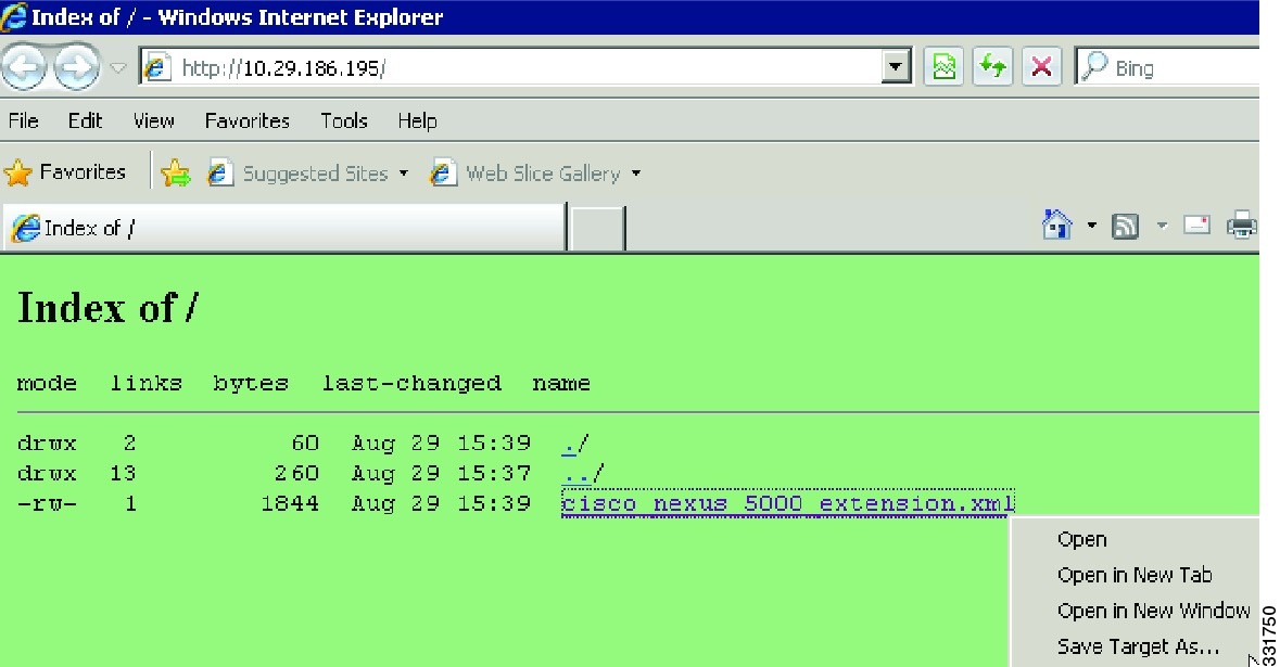
Creating FCoE Port Profiles on Cisco Nexus 5000 Series Devices
Creating vHBAs on Cisco UCS Servers and Binding to Port Profiles
Binding vHBAs to Port Profiles Using CIMC
Using FCoE NPV
This chapter describes how to configure Fiber Channel over Ethernet (FCoE) N-port Virtulization (NPV) on the Cisco Nexus 5000 Series devices.
This chapter includes the following sections:
•
FCoE and Enhanced vPC Considerations
•
•
Information About FCoE NPV
Beginning with Cisco NX-OS Release 5.0(3)N2(1) and later releases, FCoE NPV is supported on the Cisco Nexus 5000 Series devices. The FCoE NPV feature is an enhanced form of FCoE Initialization Protocol (FIP) snooping that provides a secure method to connect FCoE-capable hosts to an FCoE-capable FCoE forwarder (FCF) device. The FCoE NPV feature provides the following benefits:
•
•
•
FCoE NPV Licensing
You can enable FCoE NPV by choosing one of the following methods:
•
•
VNP Ports
Connectivity from an FCoE NPV bridge to the FCF is supported only over point-to-point links. These links can be individual Ethernet interfaces or port channel interfaces. For each FCF connected to an Ethernet interface, a vFC interface must be created and bound to it. These vFC interfaces must be configured as VNP ports.
On the VNP port, the FCoE NPV bridge emulates an FCoE-capable host with multiple enodes, each with a unique enode MAC address. By default, the VNP port is enabled in trunk mode.
Multiple VSANs can be configured on the VNP port. The FCoE VLANs that correspond to the VNP port VSANs must be configured on the bound Ethernet interface.
Note
FCoE NPV Configuration
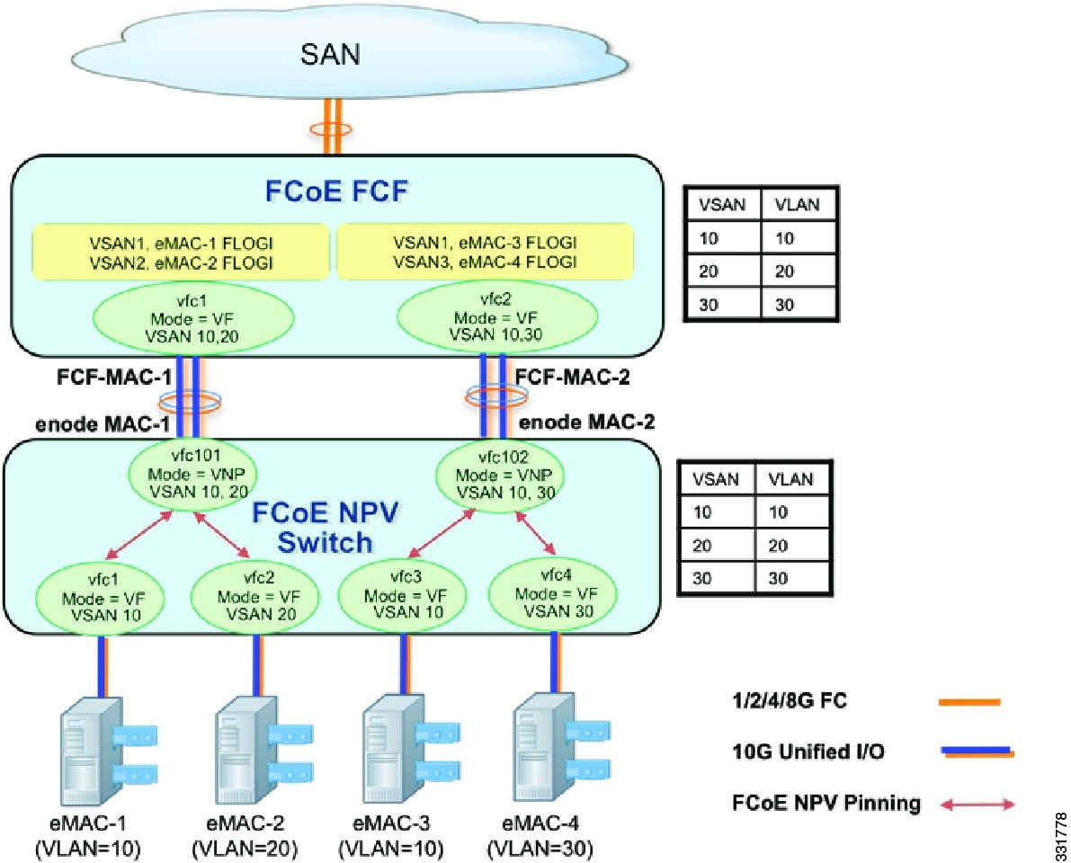
As seen in Figure 4-1, the FCoE-NPV device is proxying FIP control messages and the Fabric Login (FLOGI) between the converged network adapter (CNA) and the FCoE FCF device. An FCoE NPV, unlike a FIP snooping bridge, is VSAN-aware and will take VSANs into account when mapping (or pinning) logins from the CNA to an FCF uplink. FLOGI from the initiators (eNodes), are load balanced between the two links of each port channel interface (VNP) connecting the FCoE NPV and FCF devices.
Note
Note
Figure 4-1 FCoE NPV Pinning, FLOGI-Based on VSANs
On an FCoE NPV device, the VFC interfaces bound to server-facing ports are configured in VF mode and the VFC interfaces facing the FCoE FCF are configured as VNP ports. In the following configuration example, the FCoE NPV device uses the FCOE_NPV_PKG license to enable the FCoE NPV feature. We recommend that you selectively allow a specific list of VSANs instead of allowing all VSANs on the VNP port.
switch(config)# feature fcoe-npvswitch(config)# vsan databaseswitch(config-vsan-db)# vsan 1-2switch(config)# vlan 10switch(config-vlan)# fcoe vsan 1switch(config)# vlan 20switch(config-vlan)# fcoe vsan 2switch(config)# interface eth1/1switch(config-if)# switchport mode trunkswitch(config)# interface Eth1/2switch(config-if)# switchport mode trunkswitch(config)# interface vfc1switch(config-if)# bind interface eth1/1switch(config-if)# switchport trunk allowed vsan 1switch(config-if)# no shutswitch(config)# interface vfc2switch(config-if)# bind interface eth1/2switch(config-if)# switchport trunk allowed vsan 2switch(config-if)# no shutswitch(config)# interface vfc101switch(config-if)# switchport trunk allowed vsan 10switch(config-if)# switchport trunk allowed vsan add 20switch(config-if)# no shutswitch(config)# vsan databaseswitch(config-vsan-db)# vsan 1 interface vfc1, vfc101switch(config-vsan-db)# vsan 2 interface vfc2QoS Requirements
For Cisco Nexus 5500 Platform devices, you must configure class-fcoe in the QoS policy maps of all types.
This example shows how to configure class-fcoe in all QoS policy maps:
switch# config tswitch(config)# system qosswitch(config-sys-qos)# service-policy type qos input fcoe-default-in-policyswitch(config-sys-qos)# service-policy type queuing input fcoe-default-in-policyswitch(config-sys-qos)# service-policy type queuing output fcoe-default-out-policyswitch(config-sys-qos)# service-policy type network-qos fcoe-default-nq-policy
Note
FCoE NPV Features
The following FiberChannel NPV features are as follows:
•
•
•
•
•
Note
Interoperability with FCoE-Capable Devices
Beginning with Cisco NX-OS Release 5.0(3)N2(1), the Cisco Nexus 5000 Series device interoperates with the following FCoE-capable devices:
•
•
•
Network Design using Cisco Nexus 5000, Cisco Nexus 7000, and Cisco MDS 9500 Devices
Beginning with Cisco NX-OS Release 5.2, the Cisco Nexus 7000 Series devices supports FCoE functionality with a 32-port 10G SFP+ F1 linecard. On the Cisco MDS 9500 Multilayer Director, FCoE is supported on the 10-Gbps 8-port FCoE Module from Cisco NX-OS Release 5.2 and later releases. Based on the SAN design requirements, a combination of Cisco Nexus 7000 Series, Cisco Nexus 5000 Series, and Cisco MDS 9000 Series devices can be used to design single-hop, multi hop, or multi tier FCoE networks.
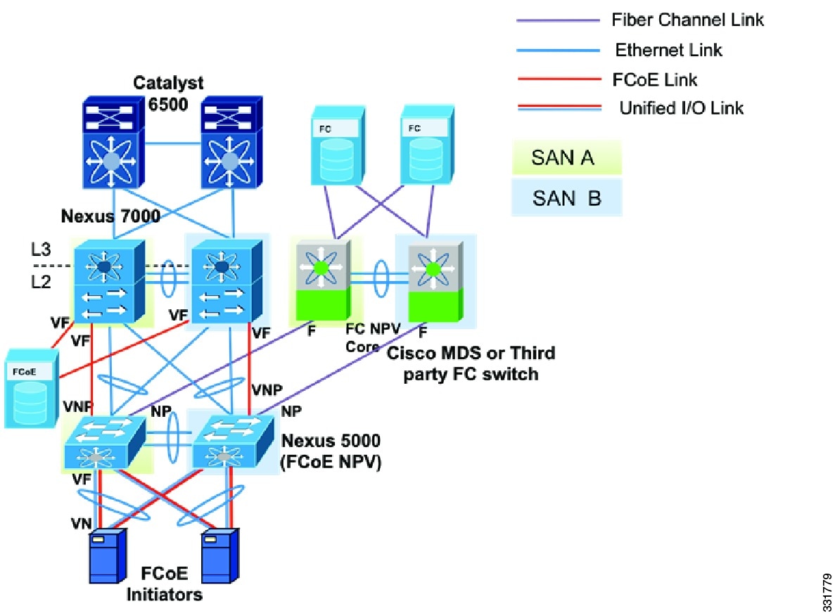
Figure 4-2 shows one recommended multi tier FCoE design topology using Cisco Nexus 7000 Series, Cisco Nexus 5000 Series, and Cisco MDS 9000 Series devices. Cisco Nexus 5000 Series devices can run FCoE NPV and FC NPV simultaneously, providing server-CNA connectivity to FCF devices while maintaining connectivity with existing SAN networks.
Figure 4-2 Converged Multi-hop FCoE Network Design Using FCoE NPV
Custom QoS Settings for ETS
By default, the Cisco Nexus 5000 Series, Cisco Nexus 7000 Series, and Cisco MDS 9000 Series devices use a CoS value of 3 for the FCoE traffic.When FCoE is enabled on a Cisco Nexus 5000 Series device, CoS 3 is automatically configured for a no-drop service (PFC setting), and in the case of congestion (ETS setting) a guaranteed bandwidth of 50 percent is allocated to FCoE traffic.
The default ETS setting for Cisco Nexus 7000 Series devices and the Cisco MDS 9000 Series devices is 70 percent for FCoE no-drop traffic class.
The following commands are required on the Cisco Nexus 7000 Series device to configure QoS settings for the FCoE traffic:
N7K-1# configure terminalN7K-1(config)# system qosN7K-1(config-sys-qos)# service-policy type network-qos default-nq-7e-policy
Note
Use of Consolidated Versus Dedicated Links
The cost/benefit tradeoff for consolidated links and dedicated links for FCoE is discussed in detail in the "Consolidated Links and Dedicated Links for FCoE" section, which covers the design considerations and link type selection you should consider when designing FCoE networks using Cisco Nexus 7000 Series and Cisco MDS 9000 Series devices.
We recommend that you use dedicated links to carry the FCoE traffic between Cisco Nexus 7000 Series and Cisco Nexus 5000 Series devices because FCoE links are part of storage Virtual Device Contents (VDCs) and not part of Ethernet VDCs. Consolidated links go to the storage VDCs of the Cisco Nexus 7000 Series devices drop Ethernet traffic carried over the link. Similarly consolidated links that are configured to be a part of Ethernet VDC on a Cisco Nexus 7000 Series device drop all FCoE traffic carried on that link. A network design using dedicated links for Ethernet and FCoE traffic makes use of the high-availability features of both LAN and SAN networks.
Because Cisco MDS 9000 Series devices do not support the switching of Ethernet traffic, we recommend that you ensure that no Ethernet VLANs get mapped to interfaces that connect Cisco Nexus 5000 Series and Cisco MDS 9000 Series devices. Directing Ethernet LAN traffic to a Cisco MDS 9000 Series devices that causes a traffic black hole and might result in loss of traffic.
Storage VDCs for Cisco Nexus 7000 Series Devices
VDCs that are available on Cisco Nexus 7000 Series devices allow virtualization at the device level, where logical entities are created to provide process separation and fault tolerance. For FCoE, dedicated links can be configured so that ingress traffic is processed in a separate and distinct VDC, which is the storage VDC.
On the Cisco Nexus 7000 Series device, you must create a storage VDC for FCoE traffic as follows:
N7K-1# configure terminalN7K-1(config)# vdc fcoe_vdc type storageNote: Creating VDC, one moment please...N7K-1(config)# limit-resource module-type f1N7K-1(config)# allow feature-set fcoeN7K-1(config-vdc)# allocate interface ethernet 3/1-32Moving ports causes all configuration that is associated to them in the source VDC to be removed.
FCoE and Enhanced vPC Considerations
Beginning with the Cisco NX-OS Release 5.1(3)N1(1), Cisco Nexus 5000 Series devices support FCoE on Enhanced vPC (EVPC). With EVPC topologies, it is important to ensure that FCoE traffic does not get forwarded from the FEXs to more than one Cisco Nexus 5000 Series device, because it violates the SAN fabric isolation rule.
This behavior is implemented by associating each FEX with only one Cisco Nexus 5000 Series device. The Cisco Nexus 2000 and Cisco Nexus 5000 pair is part of only one FCoE SAN fabric.
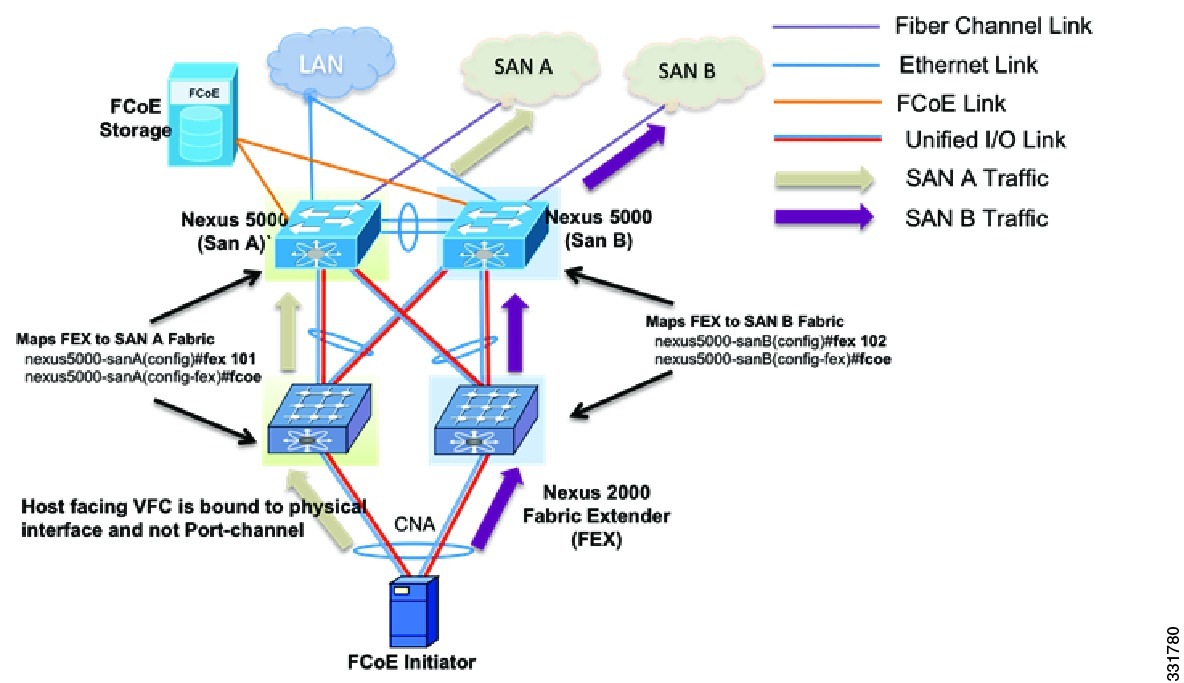
Figure 4-3 shows an FCoE network design that uses an eVPC-layer vPC. The server FCoE traffic received on the FEX is sent only to the associated Cisco Nexus 5000 Series device. Using the fcoe command for the FEX configuration associates the FEX device with one Cisco Nexus 5000 Series device. One vPC link is used for FCoE traffic, which helps to implement the SAN A and SAN B isolation.
Figure 4-3 FCoE Network Design Using eVPC-layer vPC
This example shows how to associate a FEX and a Cisco Nexus 5000 Series device with FCoE SAN fabrics:
nexus5000-sanA(config)# fex 101nexus5000-sanA(config-fex)# fcoenexus5000-sanB(config)# fex 102nexus5000-sanB(config-fex)# fcoe
Note
SAN Boot of Initiators via LACP-Based Host vPC
Beginning with Cisco NX-OS Release 5.1(3)N1(1), Cisco Nexus 5000 Series devices support the SAN boot of initiators on Link Aggregation Control Protocol (LACP) based vPC. This limitation is specific to LACP- based port channels. The host-facing VFC interfaces are bound to port channel members instead of the port channel itself. This binding ensures that the host-side VFC comes up during a SAN boot as soon as the link on the CNA/ Host Bus Adapter (HBA) comes up, without relying on the LACP-based port channel to form first.
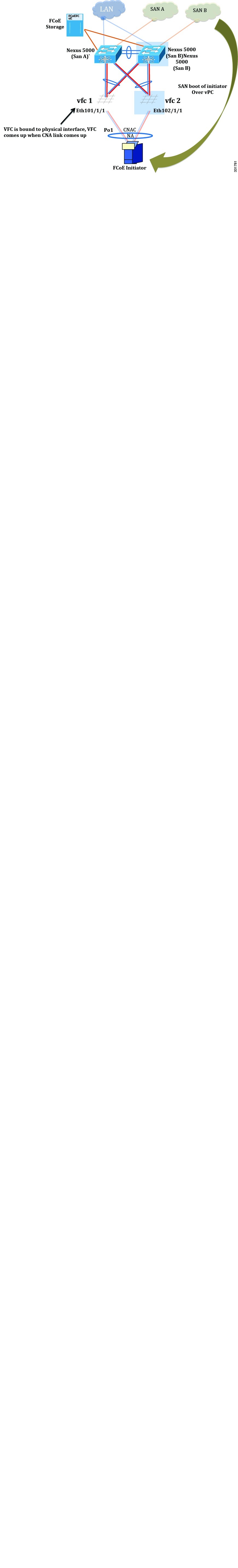
Figure 4-4 shows a network design with an initiator configured to boot from SAN via a vPC. VFC1 is bound to physical interface Eth101/1/1 that is part of port channel 1. VFC interfaces come up as soon as the channel-member state of host-facing vPC comes up, which helps the initiator to boot from SAN via the vPC.
This example shows how to configure the host-facing FEX:
nexus5000-sanA(config)#fex 101nexus5000-sanA(config-fex)#fcoenexus5000-sanA(config)#interface vfc 1nexus5000-sanA(config-if)#bind interface eth101/1/1nexus5000-sanA(config)#interface eth101/1/1nexus5000-sanA(config-if)#channel-group 1nexus5000-sanB(config)#fex 102nexus5000-sanB(config-fex)#fcoenexus5000-sanB(config)#interface vfc 1nexus5000-sanB(config-if)#bind interface eth102/1/1nexus5000-sanB(config)#interface eth102/1/1nexus5000-sanB(config-if)#channel-group 1Figure 4-4 Network Design with an Initiator Configured to Boot from SAN via a vPC
Note
Note
Note
FCoE Functionality Using the Adapter-FEX
Introduction
Beginning with Cisco NXOS 5.1(3)N1(1), Cisco Nexus 5000 Series devices, when connected to Cisco UCS servers with P81E adapters, can support FCoE over vEthernet interfaces. The Cisco UCS P81E Virtual Interface Card is a virtualization-optimized Fibre Channel over Ethernet (FCoE) PCI Express (PCIe) 2.0 x8 10-Gbps adapter designed for use with Cisco UCS C-Series rack-mount servers. When configured in Adapter-FEX mode, the two unified ports can be sliced into two FCoE channels, which creates four vHBA interfaces available to the operating system.
Figure 4-5 shows a topology implementation of FCoE over the Adapter-FEX. For FCoE over Adapter-FEX network designs, the current supported configuration is to use a vPC between the Cisco Nexus Series 5000 Series and a FEX. At the same time, the host end of the P81E adapter should be configured in Active/Standby mode. For FCoE and EVPC topologies, the FEX gets associated with one Cisco Nexus 5000 Series fabric for FCoE traffic forwarding. Because the host HBA is configured in Active/Standby mode, a separate Ethernet to vEthernet to VFC mapping is needed on the other FEX and Cisco Nexus 5000 Series pair for topology implementation of FCoE over Adapter-FEX
Figure 4-5 Topology implementation of FCoE over Adapter-FEX
The following configuration is required on the Cisco Nexus 5000 Series device for binding the VFC to vEthernet interfaces. For FCoE, the Adapter-FEX can be deployed using the Active/Standby mode on the host side.
nexus5000-sanA(config)# install feature-set virtualizationnexus5000-sanA(config)# feature-set virtualizationnexus5000-sanA(config)# feature vmfexnexus5000-sanA(config)# interface vfc 1nexus5000-sanA(config-if)# bind interface veth 1nexus5000-sanA(config-if)# interface veth 1nexus5000-sanA(config-if)# bind interface eth101/1/1 channel 3nexus5000-sanA(config-if)# interface eth101/1/1nexus5000-sanA(config-if)# switchport mode vntagnexus5000-sanA(config-if)# fex 101nexus5000-sanA(config-fex)# fcoenexus5000-sanB(config)# interface vfc 2nexus5000-sanB(config-if)# bind interface veth 2nexus5000-sanB(config-if)# interface veth 2nexus5000-sanB(config-if)# bind interface eth102/1/1 channel 4nexus5000-sanB(config-if)# interface eth102/1/1nexus5000-sanB(config-if)# switchport mode vntagnexus5000-sanB(config-if)# fex 102nexus5000-sanB(config-fex)# fcoe
Note
Note
Note
Note
Creating FCoE Port Profiles on Cisco Nexus 5000 Series Devices
The following configurations are required to create vEthernet port profiles on the Cisco Nexus 5000 Series devices and to form connectivity to vCenter:
Port Profile Configuration:
nexus5000-sanA(config)# config tnexus5000-sanA(config)# port-profile type vethernet vnic-fcoe-1nexus5000-sanA(config)# switchport mode trunknexus5000-sanA(config)# switchport trunk allowed vlan 1,100nexus5000-sanA(config)# state enabledSVS connectivity to vCenter:
nexus5000-sanA(config)# svs connection vCenter-Nexus5000nexus5000-sanA(config)# protocol vmware-vimnexus5000-sanA(config)# remote ip address 172.28.3.19 port 80 vrf managementnexus5000-sanA(config)# dvs-name SJC-LABnexus5000-sanA(config)# vmware dvs datacenter-name TME-LABnexus5000-sanA(config)# connect
Note
Creating vHBAs on Cisco UCS Servers and Binding to Port Profiles
The Adapter-FEX feature of Cisco UCS P81E adapters on UCS servers is configured by using the Cisco UCS Manager CLI. This example shows how to connect to the Cisco UCS Manager CLI and to create vHBA interfaces:
sjc-xdm-054$ ssh -l admin ucs-afex-02.cisco.comadmin@ucs-afex-02.cisco.com's password:ucs-afex-02# scope chassisucs-afex-02 /chassis # show adapterPCI Slot Product Name Serial Number Product ID Vendor-------- -------------- -------------- -------------- --------------------1 UCS VIC P81E QCI1532A34U N2XX-ACPCI01 Cisco Systems Incucs-afex-02 /chassis # scope adapter 1ucs-afex-02 /chassis/adapter # set niv-mode enableducs-afex-02 /chassis/adapter # create host-fc-if vHBA-P81E-01ucs-afex-02 /chassis/adapter # set port-profile vnic-fcoe-1ucs-afex-02 /chassis/adapter/host-fc-if *# set channel-number 7ucs-afex-02 /chassis/adapter/host-fc-if *# commitucs-afex-02 /chassis/adapter/host-fc-if # show detailName vHBA-P81E-01:World Wide Node Name: 10:00:E8:B7:48:4E:0A:A0World Wide Port Name: 20:00:E8:B7:48:4E:0A:A0FC SAN Boot: disabledPersistent LUN Binding: disabledUplink Port: 0MAC Address: E8:B7:48:4E:0A:A0CoS: N/AVLAN: NONERate Limiting: N/APCIe Device Order: ANYEDTOV: 2000RATOV: 10000Maximum Data Field Size: 2048Channel Number: 5Port Profile: vnic-fcoe-1
Note
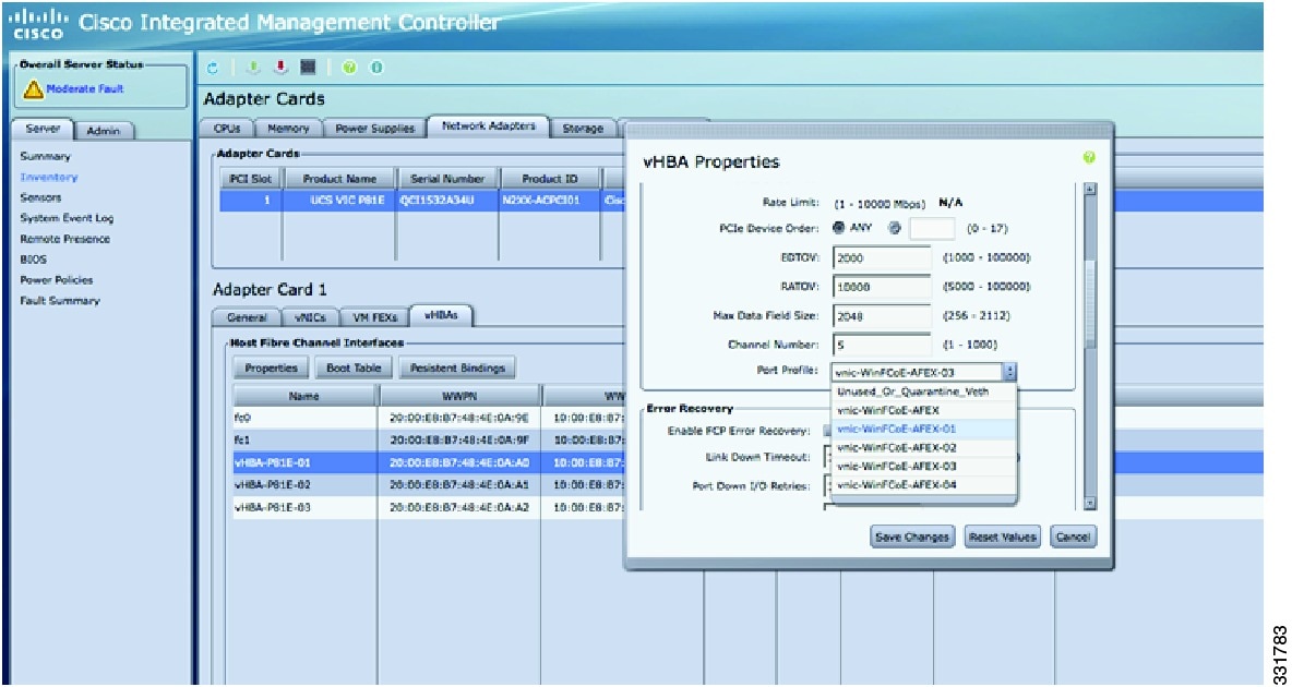
Binding vHBAs to Port Profiles Using CIMC
Virtual HBA interfaces created using the UCS C-Series Server CLI can be mapped to port profiles using the CIMC GUI. CIMC is the management service for the UCS C-Series server and runs within the server. The CIMC component can be accessed using a web browser.
Port profiles created on Cisco Nexus 5000 Series devices are pushed to the Cisco UCS P81E adapter using a VNTag link. VNTag is a unique tag that is assigned by the adapter to identify the source and destination vNIC. Port profiles appear in the drop-down menu of CIMC.
Figure 4-6 shows how to map port profiles to vHBA interfaces using the CIMC tool.
Figure 4-6 Mapping port profiles to vHBA interfaces using the CIMC tool