Feedback
Contents
- Configuring Virtual Port Channels
- vPC Overview
- vPC Terminology
- Fabric Extender Terminology
- Cisco Nexus 5000 Series Switch vPC Topology
- Single Homed Fabric Extender vPC Topology
- Dual Homed Fabric Extender vPC Topology
- vPC Domain
- Peer-Keepalive Link and Messages
- Compatibility Parameters for vPC Peer Links
- Configuration Parameters That Must Be Identical
- Configuration Parameters That Should Be Identical
- vPC Peer Links
- vPC Peer Link Overview
- Manually Configured vPC Features
- vPC Number
- vPC and LACP
- vPC Peer Links and STP
- CFSoE
- vPC Guidelines and Limitations
- Enabling vPCs
- Disabling vPCs
- Creating a vPC Domain
- Configuring a vPC Keepalive Link
- Creating a vPC Peer Link
- Checking the Configuration Compatibility
- Creating an EtherChannel Host Interface
- Moving Other EtherChannels into a vPC
- Manually Configuring a vPC Domain MAC Address
- Manually Configuring the System Priority
- Manually Configuring a vPC Peer Switch Role
- Verifying the vPC Configuration
- Dual Homed Fabric Extender vPC Configuration Example
- Single Homed Fabric Extender vPC Configuration Example
- vPC Default Settings
Configuring Virtual Port Channels
This chapter describes how to configure virtual port channels (vPCs) on Cisco Nexus 5000 Series switches. It contains the following sections:
Information About vPCs
vPC Overview
A virtual port channel (vPC) allows links that are physically connected to two different Cisco Nexus 5000 Series switches or Cisco Nexus 2000 Series Fabric Extenders to appear as a single port channel by a third device (see the following figure). The third device can be a switch, server, or any other networking device. Beginning with Cisco NX-OS Release 4.1(3)N1(1), you can configure vPCs in topologies that include Cisco Nexus 5000 Series switches connected to the Fabric Extender. A vPC can provide multipathing, which allows you to create redundancy by enabling multiple parallel paths between nodes and load balancing traffic where alternative paths exist.
You configure the EtherChannels by using one of the following:
When you configure the EtherChannels in a vPC—including the vPC peer link channel—each switch can have up to 16 active links in a single EtherChannel. When you configure a vPC on a Fabric Extender, only one port is allowed in an EtherChannel.
Note
You must enable the vPC feature before you can configure or run the vPC functionality.
To enable the vPC functionality, you must create a peer-keepalive link under a vPC domain to send heartbeat messages between the two vPC peer devices.
To create a vPC peer link you configure an EtherChannel on one Cisco Nexus 5000 Series switch by using two or more Ethernet ports. On the other switch, you configure another EtherChannel again using two or more Ethernet ports. Connecting these two EtherChannels together creates a vPC peer link.
NoteWe recommend that you configure the vPC peer-link EtherChannels as trunks.
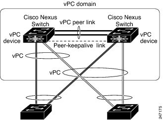
The vPC domain includes both vPC peer devices, the vPC peer-keepalive link, the vPC peer link, and all of the EtherChannels in the vPC domain connected to the downstream device. You can have only one vPC domain ID on each vPC peer device.
Note
Always attach all vPC devices using EtherChannels to both vPC peer devices.
A vPC provides the following benefits:
- Allows a single device to use an EtherChannel across two upstream devices
- Eliminates Spanning Tree Protocol (STP) blocked ports
- Provides a loop-free topology
- Uses all available uplink bandwidth
- Provides fast convergence if either the link or a switch fails
- Provides link-level resiliency
- Assures high availability
Terminology
vPC Terminology
The terminology used in vPCs is as follows:
vPC—The combined EtherChannel between the vPC peer devices and the downstream device.
vPC peer device—One of a pair of devices that are connected with the special EtherChannel known as the vPC peer link.
vPC peer link—The link used to synchronize states between the vPC peer devices.
vPC member port—Interfaces that belong to the vPCs.
Host vPC port—Fabric Extender host interfaces that belong to a vPC.
vPC domain—This domain includes both vPC peer devices, the vPC peer-keepalive link, and all of the port channels in the vPC connected to the downstream devices. It is also associated to the configuration mode that you must use to assign vPC global parameters. The vPC domain ID must be the same on both switches.
vPC peer-keepalive link—The peer-keepalive link monitors the vitality of a vPC peer Cisco Nexus 5000 Series device. The peer-keepalive link sends configurable, periodic keepalive messages between vPC peer devices.
No data or synchronization traffic moves over the vPC peer-keepalive link; the only traffic on this link is a message that indicates that the originating switch is operating and running vPCs.
Fabric Extender Terminology
The terminology used for the Cisco Nexus 2000 Series Fabric Extender is as follows:
Fabric interface—A 10-Gigabit Ethernet uplink port designated for connection from the Fabric Extender to its parent switch. A fabric interface cannot be used for any other purpose. It must be directly connected to the parent switch.
EtherChannel fabric interface—An EtherChannel uplink connection from the Fabric Extender to its parent switch. This connection consists of fabric interfaces bundled into a single logical channel.
Host interface—An Ethernet interface for server or host connectivity. These ports are 1-Gigabit Ethernet interfaces.
EtherChannel host interface—An EtherChannel downlink connection from the Fabric Extender host interface to a server port.
Note
In Release 4.1(3)N1(1), an EtherChannel host interface consists of only one host interface and can be configured either as a Link Aggregation Control Protocol (LACP) or non-LACP EtherChannel.
For further information about the Fabric Extender, refer to the Cisco Nexus 2000 Series Fabric Extender Software Configuration Guide.
Supported vPC Topologies
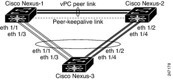
Cisco Nexus 5000 Series Switch vPC Topology
You can connect a pair of Cisco Nexus 5000 Series switches configured in a vPC directly to another switch or to a server. Up to 8 interfaces could be connected to each Cisco Nexus 5000 Series switch providing 16 interfaces bundled for the vPC pair. The topology that is shown in the following figure provides the vPC functionality to dual connected switches or servers with 10-Gigabit or 1-Gigabit Ethernet uplink interfaces.
Note
The first 8 ports on the Cisco Nexus 5010 switch and the first 16 ports on the Cisco Nexus 5020 switch are switchable 1-Gigabit and 10-Gigabit ports. You can enable vPC functionality on these ports in 1-Gigabit mode.
The switch connected to the pair of Cisco Nexus 5000 Series switches can be any standards-based Ethernet switch. Common environments to use this configuration include Blade Chassis with dual switches connected to the pair of Cisco Nexus 5000 Series switches through vPC or Unified Computing Systems connected to the pair of Cisco Nexus 5000 Series switches.
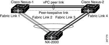
Single Homed Fabric Extender vPC Topology
You can connect a server with dual interfaces that are configured in a vPC to a pair of Cisco Nexus 2000 Series Fabric Extenders that you then connect single homed to the Cisco Nexus 5000 Series switches. The topology that is shown in the following figure provides the vPC functionality to dual homed servers with 1-Gigabit Ethernet uplink interfaces.
The Cisco Nexus 5000 Series switch can support up to 12 configured single homed Fabric Extenders (576 ports) with this topology however only 480 dual homed host servers can be configured in a vPCs with this configuration.
NoteThe current generation of Cisco Nexus 2000 Series Fabric Extender does not support EtherChannels on its host interfaces. Therefore a maximum of two links can be configured in an EtherChannel from the server where each link is connected to a separate Fabric Extender.
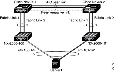
Dual Homed Fabric Extender vPC Topology
You can connect the Cisco Nexus 2000 Series Fabric Extender to two upstream Cisco Nexus 5000 Series switches and downstream to a number of single homed servers. The topology shown in the following figure provides the vPC functionality to singly connected servers with 1-Gigabit Ethernet uplink interfaces.
The Cisco Nexus 5000 Series switch can support up to 12 configured dual homed Fabric Extenders with this topology. A maximum of 480 single homed servers can be connected to this configuration.
vPC Domain
You can use the vPC domain ID to identify the vPC peer links and the ports that are connected to the vPC downstream switches.
The vPC domain is a configuration mode that you use to configure the keepalive messages and also configure other vPC peer link parameters rather than accept the default values.
To create a vPC domain, you must first create a vPC domain ID on each vPC peer switch using a number from 1 to 1000. This ID must be the same on a set of vPC peer devices. Within this domain, the system provides a loop-free topology and multipathing.
You can configure the EtherChannels and vPC peer links by using LACP or no protocol. When possible, we recommend that you use LACP with the interfaces in active mode to configure EtherChannels in each vPC to ensure an optimized, graceful recovery in a port-channel failover scenario and provides configuration checks against a configuration mismatch among the EtherChannels.
The vPC peer switches use the vPC domain ID that you configure to automatically assign a unique vPC system MAC address. Each vPC domain has a unique MAC address that is used as a unique identifier for the specific vPC-related operations, although the switches use the vPC system MAC addresses only for link-scope operations, such as LACP. We recommend that you create each vPC domain within the contiguous network with a unique domain ID. You can also configure a specific MAC address for the vPC domain, rather than having the Cisco NX-OS software assign the address.
Note
You must set a unique vPC domain ID to avoid system ID issues with LACP vPCs.
After you create a vPC domain, the Cisco NX-OS software automatically creates a system priority for the vPC domain. You can also manually configure a specific system priority for the vPC domain.
Note
If you manually configure the system priority, you must ensure that you assign the same priority value on both vPC peer switches. If the vPC peer switches have different system priority values, the vPC will not come up.
Peer-Keepalive Link and Messages
The Cisco NX-OS software uses a peer-keepalive link between the vPC peers to transmit periodic, configurable keepalive messages. You must have Layer 3 connectivity between the peer switches to transmit these messages; the system cannot bring up the vPC peer link unless a peer-keepalive link is already up and running.
If one of the vPC peer switches fails, the vPC peer switch on the other side of the vPC peer link senses the failure when it does not receive any peer-keepalive messages. The default interval time for the vPC peer-keepalive message is 1 second. You can configure the interval between 400 milliseconds and 10 seconds. You can also configure a timeout value with a range of 3 to 20 seconds; the default timeout value is 5 seconds. The peer-keepalive status is checked only when the peer-link goes down.
The vPC peer-keepalive can be carried either in the management or default VRF on the Cisco Nexus 5000 Series switch. When you configure the switches to use the management VRF, the source and destination for the keepalive messages are the mgmt 0 interface IP addresses. When you configure the switches to use the default VRF, an SVI must be created to act as the source and destination addresses for the vPC peer-keepalive messages. Ensure that both the source and destination IP addresses used for the peer-keepalive messages are unique in your network and these IP addresses are reachable from the VRF associated with the vPC peer-keepalive link.
Note
We recommend that you configure the vPC peer-keepalive link on the Cisco Nexus 5000 Series switch to run in the management VRF using the mgmt 0 interfaces. If you configure the default VRF, ensure that the vPC peer link is not used to carry the vPC peer-keepalive messages.
Compatibility Parameters for vPC Peer Links
Many configuration and operational parameters must be identical on all interfaces in the vPC. After you enable the vPC feature and configure the peer link on both vPC peer switches, Cisco Fabric Services (CFS) messages provide a copy of the configuration on the local vPC peer switch configuration to the remote vPC peer switch. The system then determines whether any of the crucial configuration parameters differ on the two switches.
Enter the show vpc consistency-parameters command to display the configured values on all interfaces in the vPC. The displayed configurations are only those configurations that would limit the vPC peer link and vPC from coming up.
The compatibility check process for vPCs differs from the compatibility check for regular EtherChannels.
Configuration Parameters That Must Be Identical
The configuration parameters in this section must be configured identically on both switches at either end of the vPC peer link or the vPC is moved into suspend mode.
Note
You must ensure that all interfaces in the vPC have the identical operational and configuration parameters listed in this section.
Enter the show vpc consistency-parameters command to display the configured values on all interfaces in the vPC. The displayed configurations are only those configurations that would limit the vPC peer link and vPC from coming up.
The switch automatically check for compatibility of these parameters on the vPC interfaces. The per-interface parameters must be consistent per interface, and the global parameters must be consistent globally.
- Port-channel mode: on, off, or active
- Link speed per channel
- Duplex mode per channel
- Trunk mode per channel:
- Spanning Tree Protocol (STP) mode
- STP region configuration for Multiple Spanning Tree (MST)
- Enable or disable state per VLAN
- STP global settings:
- STP interface settings:
- Maximum Transmission Unit (MTU)
- Quality of Service global settings
- For the Fabric Extender vPC topology, all the interface level parameters mentioned above should be identically configured for host interface from both the switches.
- Fabric Extender FEX number configured on an EtherChannel fabric interface; for the Fabric Extender vPC toplogy.
If any of these parameters are not enabled or defined on either switch, the vPC consistency check ignores those parameters.
Note
To ensure that none of the vPC interfaces are in the suspend mode, enter the show vpc brief and show vpc consistency-parameters commands and check the syslog messages.
Configuration Parameters That Should Be Identical
When any of the following parameters are not configured identically on both vPC peer switches, a misconfiguration may cause undesirable behavior in the traffic flow:
- MAC aging timers
- Static MAC entries
- VLAN interface—Each switch on the end of the vPC peer link must have a VLAN interface configured for the same VLAN on both ends and they must be in the same administrative and operational mode. Those VLANs configured on only one switch of the peer link do not pass traffic using the vPC or peer link. You must create all VLANs on both the primary and secondary vPC switches, or the VLAN will be suspended.
- Private VLAN configuration
- All ACL configurations and parameters
- Quality of service (QoS) configuration and parameters—Local parameters; global parameters must be identical
- STP interface settings:
To ensure that all the configuration parameters are compatible, we recommend that you display the configurations for each vPC peer switch once you configure the vPC.
vPC Peer Links
vPC Peer Link Overview
You can have only two switches as vPC peers; each switch can serve as a vPC peer to only one other vPC peer. The vPC peer switches can also have non-vPC links to other switches.
To make a valid configuration, you configure an EtherChannel on each switch and then configure the vPC domain. You assign the EtherChannel on each switch as a peer link. For redundancy, we recommend that you should configure at least two dedicated ports into the EtherChannel; if one of the interfaces in the vPC peer link fails, the switch automatically falls back to use another interface in the peer link.
Note
We recommend that you configure the EtherChannels in trunk mode.
Many operational parameters and configuration parameters must be the same in each switch connected by a vPC peer link. Because each switch is completely independent on the management plane, you must ensure that the switches are compatible on the critical parameters. vPC peer switches have separate control planes. After configuring the vPC peer link, you should display the configuration on each vPC peer switch to ensure that the configurations are compatible.
Note
You must ensure that the two switches connected by the vPC peer link have certain identical operational and configuration parameters.
When you configure the vPC peer link, the vPC peer switches negotiate that one of the connected switches is the primary switch and the other connected switch is the secondary switch. By default, the Cisco NX-OS software uses the lowest MAC address to elect the primary switch. The software takes different actions on each switch—that is, the primary and secondary—only in certain failover conditions. If the primary switch fails, the secondary switch becomes the operational primary switch when the system recovers, and the previously primary switch is now the secondary switch.
You can also configure which of the vPC switches is the primary switch. If you want to configure the role priority again to make one vPC switch the primary switch, configure the role priority on both the primary and secondary vPC switches with the appropriate values, shut down the EtherChannel that is the vPC peer link on both switches by entering the shutdown command, and reenable the EtherChannel on both switches by entering the no shutdown command.
For known unicast traffic, you should use the local links of the vPC because you cannot load balance traffic across the peer link. Unknown unicast, multicast, and broadcast traffic are flooded across the vPC peer link. The software keeps the multicast forwarding state synchronized between the two peers for groups learned over the vPC link. If the multicast forwarding states are learned over isolated ports on either peer, the states are not synchronized, but since the peer link is a router port, the traffic is forwarded to the peer; the peer then handles the forwarding if there are other isolated ports on that switch.
MAC addresses that are learned over vPC links are also synchronized between the peers.
Configuration information flows across the vPC peer links using the Cisco Fabric Services over Ethernet (CFSoE) protocol. All MAC addresses for those VLANs configured on both switches are synchronized between vPC peer switches. The software uses CFSoE for this synchronization.
If the vPC peer link fails, the software checks the status of the remote vPC peer switch using the peer-keepalive link, which is a link between vPC peer switches, to ensure that both switches are up. If the vPC peer switch is up, the secondary vPC switch disables all vPC ports on its switch to prevent loops and disappearing or flooding traffic. The data then forwards down the remaining active links of the EtherChannel.
The software learns of a vPC peer switch failure when the keepalive messages are not returned over the peer-keepalive link.
Use a separate link (vPC peer-keepalive link) to send configurable keepalive messages between the vPC peer switches. The keepalive messages on the vPC peer-keepalive link determines whether a failure is on the vPC peer link only or on the vPC peer switch. The keepalive messages are used only when all the links in the peer link fail.
Manually Configured vPC Features
You must manually configure the following features to conform to the primary/secondary mapping of each of the vPC peer devices:
STP root—Configure the primary vPC peer device as the highest STP root priority, and configure the secondary device with a lower root priority.
We recommend that you configure the vPC peer link interfaces as STP network ports so that Bridge Assurance is enabled on all vPC peer links
We recommend that you configure Rapid PVST+ so that the primary device is the root for all VLANs and configure MST so that the primary device is the root for all instances.
We recommend that you configure Unidirectional Link Detection (UDLD) on both sides of the vPC peer link.
vPC Number
Once you have created the vPC domain ID and the vPC peer link, you can create EtherChannels to attach the downstream switch to each vPC peer switch. That is, you create one EtherChannel from the downstream switch to the primary vPC peer switch and you create another EtherChannel from the downstream switch to the secondary peer switch.
On each vPC peer switch, you assign the same vPC number to the EtherChannel that connects to the downstream switch. You will experience minimal traffic disruption when you are creating vPCs. To simplify the configuration, you can assign the vPC ID number for each EtherChannel to be the same as the EtherChannel itself (that is, vPC ID 10 for EtherChannel 10).
Note
The vPC number that you assign to the EtherChannel connecting to the downstream switch from the vPC peer switch must be identical on both vPC peer switches.
vPC Interactions with Other Features
vPC and LACP
The Link Aggregation Control Protocol (LACP) uses the system MAC address of the vPC domain to form the LACP Aggregation Group (LAG) ID for the vPC.
You can use LACP on all the vPC EtherChannels, including those channels from the downstream switch. We recommend that you configure LACP with active mode on the interfaces on each EtherChannel on the vPC peer switches. This configuration allows you to more easily detect compatibility between switches, unidirectional links, and multihop connections, and provides dynamic reaction to run-time changes and link failures.
The vPC peer link supports 16 EtherChannel LACP interfaces. You should manually configure the system priority on the vPC peer-link switches to ensure that the vPC peer-link switches have a higher LACP priority than the downstream connected switches. A lower numerical value system priority means a higher LACP priority.
Note
When manually configuring the system priority, you must ensure that you assign the same priority value on both vPC peer switches. If the vPC peer switches have different system priority values, vPC will not come up.
vPC Peer Links and STP
When you first bring up the vPC functionality, STP reconverges. STP treats the vPC peer link as a special link and always includes the vPC peer link in the STP active topology.
We recommend that you set all the vPC peer link interfaces to the STP network port type so that Bridge Assurance is automatically enabled on all vPC peer links. We also recommend that you do not enable any of the STP enhancement features on VPC peer links.
You must configure a list of parameters to be identical on the vPC peer switches on both sides of the vPC peer link.
STP is distributed; that is, the protocol continues running on both vPC peer switches. However, the configuration on the vPC peer switch elected as the primary switch controls the STP process for the vPC interfaces on the secondary vPC peer switch.
The primary vPC switch synchronizes the STP state on the vPC secondary peer switch using Cisco Fabric Services over Ethernet (CFSoE).
The vPC manager performs a proposal/handshake agreement between the vPC peer switches that sets the primary and secondary switches and coordinates the two switches for STP. The primary vPC peer switch then controls the STP protocol for vPC interfaces on both the primary and secondary switches. We recommend that you configure the primary vPC peer switch as the highest STP root priority, and configure the secondary switch with a lower root priority.
If the primary vPC peer switch fails over to the secondary vPC peer switch, there is no change in the STP topology.
The Bridge Protocol Data Units (BPDUs) use the MAC address set for the vPC for the STP bridge ID in the designated bridge ID field. The vPC primary switch sends these BPDUs on the vPC interfaces.
Note
Display the configuration on both sides of the vPC peer link to ensure that the settings are identical. Use the show spanning-tree command to display information about the vPC.
CFSoE
The Cisco Fabric Services over Ethernet (CFSoE) is a reliable state transport mechanism that you can use to synchronize the actions of the vPC peer devices. CFSoE carries messages and packets for many features linked with vPC, such as STP and IGMP. Information is carried in CFS/CFSoE protocol data units (PDUs).
When you enable the vPC feature, the device automatically enables CFSoE, and you do not have to configure anything. CFSoE distributions for vPCs do not need the capabilities to distribute over IP or the CFS regions. You do not need to configure anything for the CFSoE feature to work correctly on vPCs.
You can use the show mac address-table command to display the MAC addresses that CFSoE synchronizes for the vPC peer link.
Note
Do not enter the no cfs eth distribute or the no cfs distribute command. CFSoE must be enabled for vPC functionality. If you do enter either of these commands when vPC is enabled, the system displays an error message.
When you enter the show cfs application command, the output displays "Physical-eth," which shows the applications that are using CFSoE.
vPC Guidelines and Limitations
vPC has the following configuration guidelines and limitations:
You must enable the vPC feature before you can configure vPC peer-link and vPC interfaces.
You must configure the peer-keepalive link before the system can form the vPC peer link.
Only EtherChannels can be in vPCs. A vPC can be configured on a normal EtherChannel (switch-to-switch vPC topology), on an EtherChannel fabric interface (fabric extender vPC topology), and on an EtherChannel host interface (host interface vPC topology).
NoteRefer to the Cisco Nexus 2000 Series Fabric Extender Software Configuration Guide for information about Fabric Extender host and fabric interfaces.
A Fabric Extender can be a member of a Host Interface vPC topology or a Fabric Extender vPC topology but not both simultaneously.
You must configure both vPC peer switches; the configuration is not automatically synchronized between the vPC peer devices.
Check that the necessary configuration parameters are compatible on both sides of the vPC peer link.
You may experience minimal traffic disruption while configuring vPCs.
You should configure all the EtherChannels in the vPC using LACP with the interfaces in active mode.
Configuring vPCs
Enabling vPCs
ProcedureDisabling vPCs
ProcedureYou can disable the vPC feature.
Note
When you disable the vPC feature, the Cisco Nexus 5000 Series switch clears all the vPC configurations.
Creating a vPC Domain
You must create identical vPC domain IDs on both the vPC peer devices. This domain ID is used to automatically form the vPC system MAC address.
Before You BeginProcedureEnsure that you have enabled the vPC feature.
You must configure both switches on either side of the vPC peer link with the following procedure.
Configuring a vPC Keepalive Link
You can configure the destination IP for the peer-keepalive link that carries the keepalive messages. Optionally, you can configure other parameters for the keepalive messages.
Before You BeginProcedureEnsure that you have enabled the vPC feature.
You must configure the vPC peer-keepalive link before the system can form the vPC peer link.
You must configure both switches on either side of the vPC peer link with the following procedure.
Command or Action Purpose Step 1 switch# configure terminal
Enters configuration mode.
Step 2 switch(config)# vpc domain domain-id
Creates a vPC domain on the switch if it does not already exist, and enters the vpc-domain configuration mode.
Step 3 switch(config-vpc-domain)# peer-keepalive destination ipaddress [hold-timeout secs | interval msecs {timeout secs} | precedence {prec-value | network | internet | critical | flash-override | flash | immediate priority | routine} | tos {tos-value | max-reliability | max-throughput | min-delay | min-monetary-cost | normal} | tos-byte tos-byte-value} | source ipaddress | vrf {name | management vpc-keepalive}]
Configures the IPv4 address for the remote end of the vPC peer-keepalive link.
Note The system does not form the vPC peer link until you configure a vPC peer-keepalive link.
The management ports and VRF are the defaults
Step 4 switch# show vpc peer-keepalive
(Optional) Displays information about the configuration for the keepalive messages.
Step 5 switch# copy running-config startup-config
(Optional) Copies the running configuration to the startup configuration.
Creating a vPC Peer Link
You can create a vPC peer link by designating the EtherChannel that you want on each switch as the peer link for the specified vPC domain. We recommend that you configure the EtherChannels that you are designating as the vPC peer link in trunk mode and that you use two ports on separate modules on each vPC peer switch for redundancy.
Before You BeginProcedureEnsure that you have enabled the vPC feature.
You must configure both switches on either side of the vPC peer link with the following procedures
Command or Action Purpose Step 1 switch# configure terminal
Enters configuration mode.
Step 2 switch(config)# interface port-channel channel-number
Selects the EtherChannel that you want to use as the vPC peer link for this switch, and enters the interface configuration mode.
Step 3 switch(config-if)# vpc peer-link
Configures the selected EtherChannel as the vPC peer link, and enters the vpc-domain configuration mode.
Step 4 switch# show vpc brief
(Optional) Displays information about each vPC, including information about the vPC peer link.
Step 5 switch# copy running-config startup-config
(Optional) Copies the running configuration to the startup configuration.
Checking the Configuration Compatibility
After you have configured the vPC peer link on both vPC peer switches, check that the configurations are consistent on all vPC interfaces.
Parameter
Default Setting
switch# show vpc consistency-parameters {global | interface port-channel channel-number} Displays the status of those parameters that must be consistent across all vPC interfaces.
This example shows how to check that the required configurations are compatible across all the vPC interfaces:
switch# show vpc consistency-parameters globalLegend:Type 1 : vPC will be suspended in case of mismatchName Type Local Value Peer Value------------- ---- ---------------------- -----------------------QoS 1 ([], [3], [0,7], [2], ([], [3], [0,7], [2],[4], [6]) [4], [6])Network QoS (MTU) 1 (1538, 2240, 0, 0, 0, (1538, 2240, 0, 0, 0,0) 0)Network Qos (Pause) 1 (F, T, F, F, F, F) (F, T, F, F, F, F)Input Queuing (Bandwidth) 1 (50, 50, 0, 0, 0, 0) (50, 50, 0, 0, 0, 0)Input Queuing (Absolute 1 (F, F, F, F, F, F) (F, F, F, F, F, F)Priority)Output Queuing (Bandwidth) 1 (50, 50, 0, 0, 0, 0) (50, 50, 0, 0, 0, 0)Output Queuing (Absolute 1 (F, F, F, F, F, F) (F, F, F, F, F, F)Priority)STP Mode 1 MST MSTSTP Disabled 1 None NoneSTP MST Region Name 1 "" ""STP MST Region Revision 1 0 0STP MST Region Instance to 1VLAN MappingSTP Loopguard 1 Disabled DisabledSTP Bridge Assurance 1 Enabled EnabledSTP Port Type 1 Normal NormalSTP MST Simulate PVST 1 Enabled EnabledAllowed VLANs - - -This example shows how to check that the required configurations are compatible for an EtherChannel interface:
switch# show vpc consistency-parameters interface port-channel 20Legend:Type 1 : vPC will be suspended in case of mismatchName Type Local Value Peer Value------------- ---- ---------------------- -----------------------Fex id 1 20 20STP Port Type 1 Default DefaultSTP Port Guard 1 None NoneSTP MST Simulate PVST 1 Default Defaultmode 1 on onSpeed 1 10 Gb/s 10 Gb/sDuplex 1 full fullPort Mode 1 fex-fabric fex-fabricShut Lan 1 No NoAllowed VLANs - 1,3-3967,4048-4093 1-3967,4048-4093Creating an EtherChannel Host Interface
To connect to a downstream server from a Cisco Nexus 2000 Series Fabric Extender you can create a EtherChannel host interface. An EtherChannel host interface can have only one host interface as a member. You need to create an EtherChannel host interface to configure a vPC on it that uses the Fabric Extender topology.
NoteSee the Cisco Nexus 2000 Series Fabric Extender Software Configuration Guide for information on attaching a Fabric Extender to a Cisco Nexus 5000 Series switch.
Before You BeginProcedureEnsure that you have enabled the vPC feature.
Ensure that the connected Fabric Extender is online.
You must configure both switches on either side of the vPC peer link with the following procedure.
Command or Action Purpose Step 1 switch# configure terminal
Enters configuration mode.
Step 2 switch(config)# interface ethernet chassis/slot/port
Specifies an interface to configure, and enters interface configuration mode.
Step 3 switch(config-if)# channel-group channel-number mode {active | passive | on}
Creates an EtherChannel host interface on the selected host interface.
Step 4 switch# show port-channel summary
(Optional) Displays information about each EtherChannel host interface.
Step 5 switch# copy running-config startup-config
(Optional) Copies the running configuration to the startup configuration.
Moving Other EtherChannels into a vPC
To connect to the downstream switch, you create a EtherChannel from the downstream switch to the primary vPC peer switch and you create another EtherChannel from the downstream switch to the secondary peer switch. Finally, working on each vPC peer switch, you assign a vPC number to the EtherChannel that connects to the downstream switch. You will experience minimal traffic disruption when you are creating vPCs.
Before You BeginProcedureEnsure that you have enabled the vPC feature.
You must configure both switches on either side of the vPC peer link with the following procedure.
Command or Action Purpose Step 1 switch# configure terminal
Enters configuration mode.
Step 2 switch(config)# interface port-channel channel-number
Selects the EtherChannel that you want to put into the vPC to connect to the downstream switch, and enters the interface configuration mode.
Note A vPC can be configured on a normal EtherChannel (physical vPC topology), on an EtherChannel fabric interface (fabric extender vPC topology), and on an EtherChannel host interface (host interface vPC topology)
Step 3 switch(config-if)# vpc number
Configures the selected EtherChannel into the vPC to connect to the downstream switch. The range is from 1 to 4096.
The vPC number that you assign to the EtherChannel connecting to the downstream switch from the vPC peer switch must be identical on both vPC peer switches.
Step 4 switch# show vpc brief
(Optional) Displays information about each vPC.
Step 5 switch# copy running-config startup-config
(Optional) Copies the running configuration to the startup configuration.
Manually Configuring a vPC Domain MAC Address
You create the vPC peer link by designating the EtherChannel that you want on each switch as the peer link for the specified vPC domain. We recommend that you configure the EtherChannels that you are designating as the vPC peer link in trunk mode and that you use two ports on separate modules on each vPC peer switch for redundancy.
Before You BeginProcedureEnsure that you have enabled the vPC feature.
You must configure both switches on either side of the vPC peer link with the following procedure.
Command or Action Purpose Step 1 switch# configure terminal
Enters configuration mode.
Step 2 switch(config)# vpc domain domain-id
Selects an existing vPC domain on the switch, or creates a new vPC domain, and enters the vpc-domain configuration mode. There is no default domain-id ; the range is from 1 to 1000.
Step 3 switch(config-vpc-domain)# system-mac mac-address
Enters the MAC address that you want for the specified vPC domain in the following format: aaaa.bbbb.cccc.
Step 4 switch# show vpc role
(Optional) Displays the vPC system MAC address.
Step 5 switch# copy running-config startup-config
(Optional) Copies the running configuration to the startup configuration.
Manually Configuring the System Priority
When you create a vPC domain, the system automatically creates a vPC system priority. However, you can also manually configure a system priority for the vPC domain.
Note
We recommend that you manually configure the vPC system priority when you are running LACP to ensure that the vPC peer switches are the primary switches on LACP. When you manually configure the system priority, ensure that you configure the same priority value on both vPC peer switches. If these values do not match, vPC will not come up.
Before You BeginProcedureEnsure that you have enabled the vPC feature.
You must configure both switches on either side of the vPC peer link with the following procedure.
Command or Action Purpose Step 1 switch# configure terminal
Enters configuration mode.
Step 2 switch(config)# vpc domain domain-id
Selects an existing vPC domain on the switch, or creates a new vPC domain, and enters the vpc-domain configuration mode. There is no default domain-id ; the range is from 1 to 1000.
Step 3 switch(config-vpc-domain)# system-priority priority
Enters the system priority that you want for the specified vPC domain. The range of values is from 1 to 65535. The default value is 32667.
Step 4 switch# show vpc brief
(Optional) Displays information about each vPC, including information about the vPC peer link.
Step 5 switch# copy running-config startup-config
(Optional) Copies the running configuration to the startup configuration.
Manually Configuring a vPC Peer Switch Role
By default, the Cisco NX-OS software elects a primary and secondary vPC peer switch after you configure the vPC domain and both sides of the vPC peer link. However, you may want to elect a specific vPC peer switch as the primary switch for the vPC. Then, you would manually configure the role value for the vPC peer switch that you want as the primary switch to be lower than the other vPC peer switch.
vPC does not support role preemption. If the primary vPC peer switch fails, the secondary vPC peer switch takes over to become operationally the vPC primary switch. However, the original operational roles are not restored when the formerly primary vPC comes up again.
Before You BeginProcedureEnsure that you have enabled the vPC feature.
You must configure both switches on either side of the vPC peer link with the following procedure.
Command or Action Purpose Step 1 switch# configure terminal
Enters configuration mode.
Step 2 switch(config)# vpc domain domain-id
Selects an existing vPC domain on the switch, or creates a new vPC domain, and enters the vpc-domain configuration mode. There is no default domain-id ; the range is from 1 to 1000.
Step 3 switch(config-vpc-domain)# role priority priority
Enters the role priority that you want for the vPC system priority. The range of values is from 1 to 65535. The default value is 32667.
Step 4 switch# show vpc brief
(Optional) Displays information about each vPC, including information about the vPC peer link.
Step 5 switch# copy running-config startup-config
(Optional) Copies the running configuration to the startup configuration.
Verifying the vPC Configuration
Use the following commands to display vPC configuration information:
Command
Purpose
switch# show feature Displays whether vPC is enabled or not.
switch# show port-channel capacity Displays how many EtherChannels are configured and how many are still available on the switch.
switch# show running-config vpc Displays running configuration information for vPCs.
switch# show vpc brief Displays brief information on the vPCs.
switch# show vpc consistency-parameters Displays the status of those parameters that must be consistent across all vPC interfaces.
switch# show vpc peer-keepalive Displays information on the peer-keepalive messages.
switch# show vpc role Displays the peer status, the role of the local switch, the vPC system MAC address and system priority, and the MAC address and priority for the local vPC switch.
switch# show vpc statistics Displays statistics on the vPCs.
Note This command displays the vPC statistics only for the vPC peer device that you are working on.
For detailed information about the fields in the output from these commands, see the Cisco Nexus 5000 Series Command Reference.
vPC Example Configurations
Dual Homed Fabric Extender vPC Configuration Example
The following example shows how to configure the dual homed Fabric Extender vPC topology using the management VRF to carry the peer-keepalive messages on switch NX-5000-1 as shown in following figure:
Before You BeginProcedureEnsure that the Cisco Nexus 2000 Series Fabric Extender NX-2000-100 is attached and online.
Step 1 Enable vPC and LACP. NX-5000-1# configure terminalNX-5000-1(config)# feature lacpNX-5000-1(config)# feature vpcStep 2 Create the vPC domain and add the vPC peer-keepalive link. NX-5000-1(config)# vpc domain 1NX-5000-1(config-vpc-domain)# peer-keepalive destination 10.10.10.237NX-5000-1(config-vpc-domain)# exitStep 3 Configure the vPC peer link as a two port Etherchannel. NX-5000-1(config)# interface ethernet 1/1-2NX-5000-1(config-if-range)# switchport mode trunkNX-5000-1(config-if-range)# switchport trunk allowed vlan 20-50NX-5000-1(config-if-range)# switchport trunk native vlan 20NX-5000-1(config-if-range)# channel-group 20 mode activeNX-5000-1(config-if-range)# exitNX-5000-1(config)# interface port-channel 20NX-5000-1(config-if)# vpc peer-linkNX-5000-1(config-if)# exitStep 4 Configure the Fabric Extender NX-2000-100. NX-5000-1(config)# fex 100NX-5000-1(config-fex)# pinning max-links 1NX-5000-1(fex)# exitStep 5 Configure the fabric EtherChannel links for the Fabric Extender NX-2000-100. NX-5000-1(config)# interface ethernet 1/20NX-5000-1(config-if)# channel-group 100NX-5000-1(config-if)# exitNX-5000-1(config)# interface port-channel 100NX-5000-1(config-if)# switchport mode fex-fabricNX-5000-1(config-if)# vpc 100NX-5000-1(config-if)# fex associate 100NX-5000-1(config-if)# exitStep 6 Configure the host interface ports on the Fabric Extender NX-2000-100. switch(config)# interface ethernet 100/1/1-48switch(config-if)# switchport mode accessswitch(config-if)# switchport access vlan 50switch(config-if)# no shutdownswitch(config-if)# exitStep 7 Save the configuration. switch(config)# copy running-config startup-config
Single Homed Fabric Extender vPC Configuration Example
The following example shows how to configure the single homed Fabric Extender vPC topology using the default VRF to carry the peer-keepalive messages on switch NX-5000-1 as shown in following figure:
NoteThe following example only shows the configuration of NX-5000-1 which is connected to the Fabric Extender NX-2000-100. You must repeat these steps on its vPC peer, NX-5000-2, which is connected to the Fabric Extender NX-2000-101.
Before You BeginProcedureEnsure that the Cisco Nexus 2000 Series Fabric Extenders NX-2000-100 and NX-2000-101 are attached and online.
Step 1 Enable vPC and LACP. NX-5000-1# configure terminalNX-5000-1(config)# feature lacpNX-5000-1(config)# feature vpcStep 2 Enable SVI interfaces, create the VLAN and SVI to be used by the vPC peer-keepalive link. NX-5000-1(config)# feature interface-vlanNX-5000-1(config)# vlan 900NX-5000-1(config-vlan)# int vlan 900NX-5000-1(config-if)# ip address 10.10.10.236 255.255.255.0NX-5000-1(config-if)# no shutdownNX-5000-1(config-if)# exitStep 3 Create the vPC domain and add the vPC peer-keepalive link in the default VRF. NX-5000-1(config)# vpc domain 30NX-5000-1(config-vpc-domain)# peer-keepalive destination 10.10.10.237 source 10.10.10.236 vrf defaultNX-5000-1(config-vpc-domain)# exit
Note VLAN 900 must not be trunked across the vPC peer-link because it carries the vPC peer-keepalive messages. There must be an alternative path between switches NX-5000-1 and NX-5000-2 for the vPC peer-keepalive messages.
Step 4 Configure the vPC peer link as a two port Etherchannel. NX-5000-1(config)# interface ethernet 1/1-2NX-5000-1(config-if-range)# switchport mode trunkNX-5000-1(config-if-range)# switchport trunk allowed vlan 20-50NX-5000-1(config-if-range)# switchport trunk native vlan 20NX-5000-1(config-if-range)# channel-group 30 mode activeNX-5000-1(config-if-range)# exitNX-5000-1(config)# interface port-channel 30NX-5000-1(config-if)# vpc peer-linkNX-5000-1(config-if)# exitStep 5 Configure the Fabric Extender NX-2000-100. NX-5000-1(config)# fex 100NX-5000-1(config-fex)# pinning max-links 1NX-5000-1(fex)# exitStep 6 Configure the fabric EtherChannel links for the Fabric Extender NX-2000-100. NX-5000-1(config)# interface ethernet 1/20-21NX-5000-1(config-if)# channel-group 100NX-5000-1(config-if)# exitNX-5000-1(config)# interface port-channel 100NX-5000-1(config-if)# switchport mode fex-fabricNX-5000-1(config-if)# fex associate 100NX-5000-1(config-if)# exitStep 7 Configure a vPC server port on on the Fabric Extender NX-2000-100. NX-5000-1(config-if)# interface ethernet 100/1/1NX-5000-1(config-if)# switchport mode trunkNX-5000-1(config-if)# switchport trunk native vlan 100NX-5000-1(config-if)# switchport trunk allowed vlan 100-105NX-5000-1(config-if)# channel-group 600NX-5000-1(config-if)# no shutdownNX-5000-1(config-if)# exitNX-5000-1(config)# interface port-channel 600NX-5000-1(config-if)# vpc 600NX-5000-1(config-if)# no shutdownNX-5000-1(config-if)# exitStep 8 Save the configuration. NX-5000-1(config)# copy running-config startup-config