Feedback
Contents
- Overview
- Information About Cisco Nexus 5000 Series Switches
- Fibre Channel over Ethernet
- Data Center I/O Consolidation
- Virtual Interfaces
- Chassis
- Expansion Modules
- Fabric Extender
- Ethernet Interfaces
- Fibre Channel Interfaces
- Management Interfaces
- Ethernet Switching
- FCoE and Fibre Channel Switching
- QoS
- Virtual Port Channels
- Serviceability
- Switched Port Analyzer
- Ethanalyzer
- Call Home
- Online Diagnostics
- Simple Network Management Protocol
- Role-Based Access Control
- Configuring with CLI, XML Management Interface, or SNMP
- Configuring with Cisco Data Center Network Manager
- Configuring with Cisco MDS Fabric Manager
- Network Security Features
- Virtual Device Contexts
- Licensing
- Ethernet TOR Switch Topology
- Fabric Extender Deployment Topology
- Data Center I/O Consolidation Topology
- Supported Standards
Overview
This chapter describes the Cisco Nexus 5000 Series switches. It includes the following sections:
Information About Cisco Nexus 5000 Series Switches
The Cisco Nexus 5000 Series is a family of top-of-rack switches for the data center. The Cisco Nexus 5000 Series offers high-speed Ethernet switching and supports Fibre Channel over Ethernet (FCoE) to provide data center I/O consolidation.
Currently, the Cisco Nexus 5000 Series has two switches: the Cisco Nexus 5010 switch which provides 20 fixed Ethernet ports in a 1 RU switch, and the Cisco Nexus 5020 switch which provides 40 fixed Ethernet ports in a 2 RU switch. Optional expansion modules provide Fibre Channel ports and additional Ethernet ports.
New Technologies in the Cisco Nexus 5000 Series
Fibre Channel over Ethernet
Fibre Channel over Ethernet (FCoE) allows Fibre Channel traffic to be encapsulated over a physical Ethernet link. FCoE frames use a unique EtherType so that FCoE traffic and standard Ethernet traffic can be carried on the same link.
Classic Ethernet is a best-effort protocol; in the event of congestion, Ethernet will discard packets, relying on higher level protocols to provide retransmission and other reliability mechanisms. Fibre Channel traffic requires a lossless transport layer; as a data storage protocol, it is unacceptable to lose a single data packet. Native Fibre Channel implements a lossless service at the transport layer using a buffer-to-buffer credit system.
For FCoE traffic, the Ethernet link must provide a lossless service. Ethernet links on Cisco Nexus 5000 Series switches provide two mechanisms to ensure lossless transport for FCoE traffic: link-level flow control and priority flow control.
IEEE 802.3x link-level flow control allows a congested receiver to signal the far end to pause the data transmission for a short period of time. The pause functionality is applied to all the traffic on the link.
The priority flow control (PFC) feature applies pause functionality to specific classes of traffic on the Ethernet link. For example, PFC can provide lossless service for the FCoE traffic and best-effort service for the standard Ethernet traffic. PFC can provide different levels of service to specific classes of Ethernet traffic (using IEEE 802.1p traffic classes).
Data Center I/O Consolidation
I/O consolidation allows a single network technology to carry IP, SAN, and IPC traffic. FCoE is the single network technology that allows I/O consolidation. The upper Fibre Channel layers are unchanged, so the Fibre Channel operational model is maintained. FCoE network management and configuration is similar to a native Fibre Channel network.
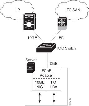
Cisco Nexus 5000 Series switches use FCoE to carry Fibre Channel and Ethernet traffic on the same physical Ethernet connection between the switch and the server. At the server, the connection terminates to a converged network adapter (CNA). The adapter presents two interfaces to the server’s operating system (OS): one Ethernet NIC interface and one Fibre Channel host bus adapter (HBA) interface.
The server OS is not aware of the FCoE encapsulation (see the following figure). At the switch, the incoming Ethernet port separates the Ethernet and Fibre Channel traffic (using EtherType to differentiate the frames). Ethernet frames and Fibre Channel frames are switched to their respective network-side interfaces.
Cisco Nexus 5000 Series switches provide quality of service (QoS) capabilities to ensure lossless or best-effort service across the switch. For Fibre Channel traffic (FCoE) you should apply the lossless QoS classes. By default, best-effort service is applied to all of the Ethernet traffic. You can configure different QoS levels for specific classes of Ethernet traffic.
Virtual Interfaces
When FCoE is enabled, a physical Ethernet cable carries traffic for a logical Fibre Channel connection.
The Cisco Nexus 5000 Series switch uses virtual interfaces to represent the logical Fibre Channel connections. For configuration purposes, virtual Fibre Channel interfaces are implemented as Layer 2 subinterfaces of the physical Ethernet interface.
Ethernet features (such as the link debounce timer and VLAN membership) are configured on the physical Ethernet interface. Logical Fibre Channel features (such as VSAN membership) are configured on the virtual Fibre Channel interfaces.
Cisco Nexus 5000 Series Switch Hardware
Chassis
The Cisco Nexus 5000 Series includes the Cisco Nexus 5010 and Cisco Nexus 5020 switches.
The Cisco Nexus 5010 switch is a 1 RU chassis and the Cisco Nexus 5020 switch is a 2 RU chassis designed for rack mounting. The chassis supports redundant fans and power supplies.
The Cisco Nexus 5000 Series switching fabric is low latency, nonblocking, and supports Ethernet frame sizes from 64 to 9216 bytes.
Refer to the Cisco Nexus 5000 Series Hardware Installation Guide for hardware configuration details.
Expansion Modules
The Cisco Nexus 5010 switch has one slot and the Cisco Nexus 5020 switch has two slots for optional expansion modules. The following expansion modules are available:
N5K-M1404 provides four 10-Gigabit Ethernet ports and four 1/2/4-Gigabit Fibre Channel ports.
N5K-M1600 provides six 10-Gigabit Ethernet ports.
N5K-M1008 provides eight 1/2/4-Gigabit Fibre Channel ports.
The expansion modules are field-replaceable units (FRUs) that support online insertion and removal (OIR).
Refer to the Cisco Nexus 5000 Series Hardware Installation Guide for details about the optional expansion modules.
Fabric Extender
The Cisco Nexus 5000 Series switch supports the optional Cisco Nexus 2000 Series Fabric Extender. The Fabric Extender is a fixed configuration chassis designed to deliver additional connectivity and is configured from the parent switch as a remote module
The Cisco Nexus 2148T Fabric Extender provides 48 1-Gigabit Ethernet host interfaces and is connected to its parent switch using four 10-Gigabit Ethernet ports.
Refer to the Cisco Nexus 2000 Series Fabric Extender Software Configuration Guide for an overview of the Fabric Extender and configuration details.
Ethernet Interfaces
The Cisco Nexus 5010 switch has 20 fixed 10-Gigabit Ethernet ports equipped with SFP+ interface adapters. The first 8 ports are switchable 1-Gigabit and 10-Gigabit ports. Up to 6 additional 10-Gigabit Ethernet ports are available on an expansion module.
The Cisco Nexus 5020 switch has 40 fixed 10-Gigabit Ethernet ports equipped with SFP+ interface adapters. The first 16 ports are switchable 1-Gigabit and 10-Gigabit ports. Up to 12 additional 10-Gigabit Ethernet ports are available on the expansion modules.
All of the 10-Gigabit Ethernet ports support FCoE. Each port can be used as a downlink (connected to a server) or as an uplink (to the data center LAN).
Fibre Channel Interfaces
Fibre Channel ports are optional on the Cisco Nexus 5000 Series switch. When you use expansion modules up to 8 Fibre Channel ports are available on the Cisco Nexus 5010 switch and up to 16 Fibre Channel ports are available on the Cisco Nexus 5020 switch.
Each Fibre Channel port can be used as a downlink (connected to a server) or as an uplink (to the data center SAN fabric).
Cisco Nexus 5000 Series Switch Software
Ethernet Switching
FCoE and Fibre Channel Switching
QoS
Cisco Nexus 5000 Series switches provide quality of service (QoS) capabilities such as traffic prioritization and bandwidth allocation on egress interfaces.
The default QoS configuration on the switch provides lossless service for Fibre Channel and FCoE traffic. QoS can be configured to provide additional classes of service for Ethernet traffic.
Virtual Port Channels
A virtual port channel (vPC) allows links that are physically connected to two different Cisco Nexus 5000 Series switches or Cisco Nexus 2000 Series Fabric Extenders to appear as a single port channel. A vPC can provide multipathing, which allows you to create redundancy by enabling multiple parallel paths between nodes and load balancing traffic where alternative paths exist.
Serviceability
Call Home
The Call Home feature continuously monitors hardware and software components to provide e-mail-based notification of critical system events. A versatile range of message formats is available for optimal compatibility with pager services, standard e-mail, and XML-based automated parsing applications. The feature offers alert grouping capabilities and customizable destination profiles. This feature can be used, for example, to directly page a network support engineer, send an e-mail message to a network operations center (NOC), and employ Cisco AutoNotify services to directly generate a case with the Cisco Technical Assistance Center (TAC). This feature is a step toward autonomous system operation, which enables networking devices to inform IT when a problem occurs and helps to ensure that the problem is resolved quickly.
Online Diagnostics
Cisco generic online diagnostics (GOLD) is a suite of diagnostic facilities to verify that hardware and internal data paths are operating as designed. Boot-time diagnostics, continuous monitoring, and on-demand and scheduled tests are part of the Cisco GOLD feature set. GOLD allows rapid fault isolation and continuous system monitoring.
Switch Management
Configuration Methods
Configuring with CLI, XML Management Interface, or SNMP
You can configure Cisco Nexus 5000 Series switches using the command-line interface (CLI), the XML management interface over SSH, or SNMP as follows:
CLI —You can configure switches using the CLI from an SSH session, a Telnet session, or the console port. SSH provides a secure connection to the device.
XML Management Interface over SSH—You can configure switches using the XML management interface, which is a programming interface based on the NETCONF protocol that complements the CLI functionality. For more information, see the Cisco NX-OS XML Interfaces User Guide.
SNMP—SNMP allows you to configure switches using Management Information Bases (MIBs).
Virtual Device Contexts
Cisco NX-OS can segment operating system and hardware resources into virtual device contexts (VDC) that emulate virtual devices. The Cisco Nexus 5000 Series switch does not support multiple VDCs. All switch resources are managed in the default VDC.
For more information, see the Cisco Nexus 7000 Series NX-OS Getting Started with Virtual Device Contexts, Release 4.1.
Licensing
The Cisco Nexus 5000 Series switch is shipped with its licenses installed. The switch provides commands to manage the licenses and install additional licenses.
Typical Deployment Topologies
Ethernet TOR Switch Topology
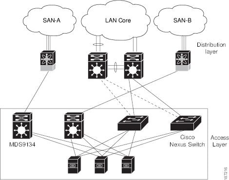
The Cisco Nexus 5000 Series switch can be deployed as a 10-Gigabit Ethernet top-of-rack (TOR) switch, with uplinks to the data center LAN distribution layer switches. An example configuration in shown in the following figure.
In this example, the blade server rack incorporates blade switches that support 10-Gigabit Ethernet uplinks to the Cisco Nexus 5000 Series switch. The blade switches do not support FCoE, so there is no FCoE traffic and no Fibre Channel ports on the Cisco Nexus 5000 Series switch.
In the example configuration, the Cisco Nexus 5000 Series switch has Ethernet uplinks to two Catalyst switches. If STP is enabled in the data center LAN, the links to one of the switches will be STP active and the links to the other switch will be STP blocked.
All of the server-side ports on the Cisco Nexus 5000 Series switch are running standard Ethernet. FCoE is not required, so the server ports are connected using 10-Gigabit Ethernet NICs.
The servers are connected to the data center SAN through MDS 9134 SAN switches. The server Fibre Channel ports require standard Fibre Channel HBAs.
Fabric Extender Deployment Topology
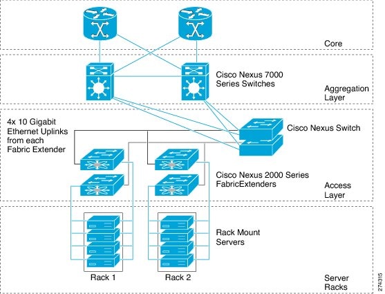
The following figure shows a simplfied configuration using the Cisco Nexus 2000 Series Fabric Extender in combination with the Cisco Nexus 5000 Series switch to provide a simplified and cost-effective 1-Gigabit TOR solution.
In the example configuration, the Fabric Extender top-of-rack units provide 1-Gigabit host interfaces connected to the servers. The Fabric Extender units are attached to their parent Cisco Nexus 5000 Series switches with 10-Gigabit fabric interfaces.
Each Fabric Extender acts as a Remote I/O Module on the parent Cisco Nexus 5000 Series switch. All device configurations are managed on the Cisco Nexus 5000 Series switch and configuration information is downloaded using inband communication to the Fabric Extender.
See the Cisco Nexus 2000 Series Fabric Extender Software Configuration Guide for an overview of the Fabric Extender and configuration details.
Data Center I/O Consolidation Topology
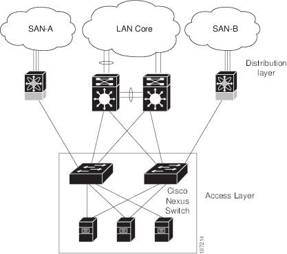
The following figure shows a typical I/O consolidation scenario for the Cisco Nexus 5000 Series switch.
The Cisco Nexus 5000 Series switch connects to the server ports using FCoE. Ports on the server require converged network adapters. For redundancy, each server connects to both switches. Dual-port CNA adapters can be used for this purpose. The CNA is configured in active-passive mode, and the server needs to support server-based failover.
On the Cisco Nexus 5000 Series switch, the Ethernet network-facing ports are connected to two Catalyst 6500 Series switches. Depending on required uplink traffic volume, there may be multiple ports connected to each Catalyst 6500 Series switch, configured as port channels. If STP is enabled in the data center LAN, the links to one of the switches will be STP active and the links to the other switch will be STP blocked.
The SAN network-facing ports on the Cisco Nexus 5000 Series switch are connected to Cisco MDS 9000 Family switches. Depending on the required traffic volume, there may be multiple Fibre Channel ports connected to each MDS 9000 Family switch, configured as SAN port channels.