Feedback
Contents
- Installing and Configuring VXLAN Gateway
- Information About the VXLAN Gateway Deployment
- Guidelines and Limitations for Cisco Nexus 1000V VXLAN Gateway
- Steps to Install and Configure VXLAN Gateway
- Configuring a Port Profile for the Uplink on the VXLAN Gateway
- Configuring a Port Profile for the VTEP on the VXLAN Gateway
- Creating Network Profiles for a VXLAN Gateway with the Nova CLI
- Configuring High Availability
- Verifying the VXLAN Gateway Installation and Configuration
- Managing the VXLAN-to-VLAN Mappings on the VXLAN Gateway
- Deleting the VXLAN Gateway from the VSM
- Feature History for VXLAN Gateways
Installing and Configuring VXLAN Gateway
This chapter contains the following sections:
- Information About the VXLAN Gateway Deployment
- Guidelines and Limitations for Cisco Nexus 1000V VXLAN Gateway
- Steps to Install and Configure VXLAN Gateway
- Configuring a Port Profile for the Uplink on the VXLAN Gateway
- Configuring a Port Profile for the VTEP on the VXLAN Gateway
- Creating Network Profiles for a VXLAN Gateway with the Nova CLI
- Configuring High Availability
- Verifying the VXLAN Gateway Installation and Configuration
- Managing the VXLAN-to-VLAN Mappings on the VXLAN Gateway
- Deleting the VXLAN Gateway from the VSM
- Feature History for VXLAN Gateways
Information About the VXLAN Gateway Deployment
The VXLAN gateway has the following deployment requirements:
- You can deploy the VXLAN Gateway on a VM or the Cisco Cloud Services platform Release 4.2(1)SP1(6.1) or later releases.
- You must connect the Cloud Services Platform appliance to a switch that supports Link Aggregation Control Protocol (LACP) based or statically configured port channels and VLAN-based trunk interfaces.
- You must have an advanced mode license to set up the VSM .
- vCPU or Memory requirements—You will need three vCPUs, 2-GB RAM, and 3-GB virtual disk space for each VXLAN gateway Virtual Service Blade (VSB).
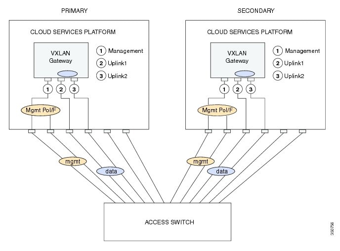
This figure shows the VXLAN gateway deployment.
Guidelines and Limitations for Cisco Nexus 1000V VXLAN Gateway
VXLAN Gateways have the following configuration guidelines and limitations:
- You must configure the VSM to use the Layer 3 control. We strongly recommend that the VSM Layer 3 control is through mgmt 0. For more information about Layer 3 control, see the Cisco Nexus 1000V Installation and Upgrade Guide and Cisco Nexus 1000V System Management Configuration Guide.
- You must configure the uplink for the gateway module as a LACP or a static port channel. The VXLAN Gateway does not function if gateways are configured in the MAC-pinning mode.
- A single VSM can manage a maximum of fourVXLAN Gateway high availability (HA) clusters.
- You must configure the HA mode of the VXLAN Gateway as standalone or primary/secondary so that when you bring up the VXLAN Gateway, the HA state is either active or standby and the VXLAN-to-VLAN mappings are either active or pending. If you do not configure an HA role for the VXLAN Gateway, when you bring up the VXLAN Gateway, the HA state is unknown, and VXLAN-to-VLAN traffic is not processed.
- You must configure the underlying Cloud Services Platform with an uplink type that is flexible (type 5). VXLAN Gateways use two physical interfaces. You must set the interfaces in the passthrough mode. In addition, you must set at least one physical or a port channel interface must be set up to carry management traffic.
- Ensure you do not configure PVLAN on the VLANs used for VXLAN-VLAN mappings.
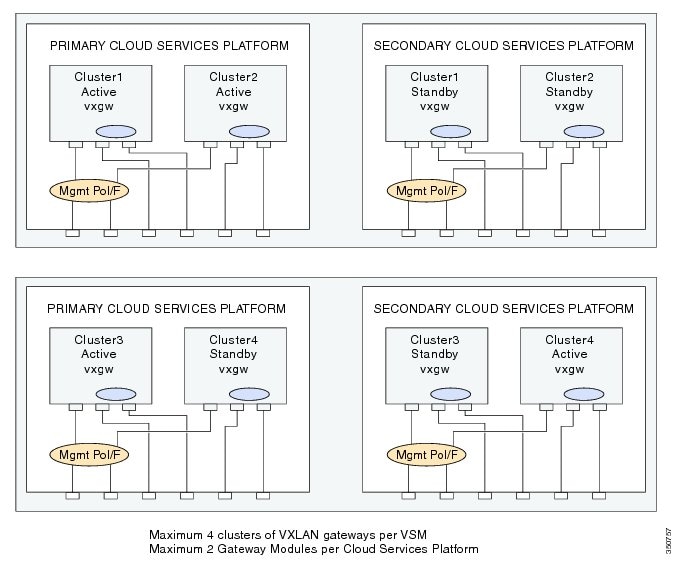
The following illustration displays the maximum allowed VXLAN Gateway deployment managed by a single VSM. It displays four Cloud Services Platform devices and each Cloud Services Platform device hosting two VXLAN Gateway modules. Four HA clusters of gateway modules are setup with each cluster consisting of an active/standby pair of modules.
Steps to Install and Configure VXLAN Gateway
Procedure
Command or Action Purpose
Step 1 Create two port profiles on the switch (VSM), one for the uplinks on the gateway and one for the VTEP interface. For details, see the Configuring a Port Profile for the Uplink on the VXLAN Gateway topic and the Configuring a Port Profile for the VTEP on the VXLAN Gateway topic.
Step 2 Install VXLAN Gateway either on a Cisco Nexus Cloud Services Platform (CSP) or a virtual machine (VM). For details, see the Cisco Nexus 1000V for KVM Software Installation Guide.
Step 3 Create Network Profiles for the VXLAN Gateway using the Nova? Quantum? command line interface or the OpenStack Horizon Dashboard.
For details, see the Creating Network Profiles for a VXLAN Gateway with the Nova CLI topic.
Step 4 Configure High Availability on the VSMs. You must configure the HA mode of the VXLAN Gateway as standalone or primary/secondary so that when you bring up the VXLAN Gateway, the HA state is either active or standby and the VXLAN-to-VLAN mappings are either active or pending. If you do not configure an HA role for the VXLAN Gateway, when you bring up the VXLAN Gateway, the HA state is unknown, and VXLAN-to-VLAN traffic is not processed.
For details, see the Configuring High Availability topic.
Step 5 Verify the VXLAN Gateway installation and configuration. (Optional) For details, see the Verifying the VXLAN Gateway Installation and Configuration topic.
Step 6 Boot the VXLAN Gateway VM. For details, see the Cisco Nexus 1000V for KVM Software Installation Guide.
Step 7 Set up the VXLAN-to-VLAN mappings on the VXLAN Gateway. For details, see the Managing the VXLAN-to-VLAN Mappings on the VXLAN Gateway topic.
Configuring a Port Profile for the Uplink on the VXLAN Gateway
Before installing the VXLAN gateway, you must create two port profiles on the switch (VSM), one for the uplinks on the gateway and one for the VTEP interface.
To create a suitable port profile that can be applied to the uplink of a VXLAN gateway service module, use the procedure below:
Before You BeginProcedure
- Ensure that the VSM is configured in the Advanced mode by entering the svs switch edition advanced configuration command to enable Advanced mode.
- Ensure LACP is configured by entering the feature lacp configuration command on the VSM.
- Offload the LACP operation by entering the lacp offload configuration command on the VSM..
- Ensure that the VXLAN feature is enabled on the VSM by entering the feature segmentation configuration command to enable VXLANs on the VSM.
- Ensure that the VXLAN gateway is enabled on the VSM by entering the feature vxlan-gateway configuration command.
- Ensure that the interfaces of the upstream switch are configured with matching port channel and VLAN trunk configuration.
This example displays how to configure and display the gateway mappings:
vsm(config)# port-profile type ethernet gw-uplink
vsm(config)# switchport mode trunk
vsm(config)# switchport trunk allowed vlan 1545
vsm(config)# mtu 1550
vsm(config-port-prof)# service instance 1
vsm(config-port-prof-srv)# encapsulation dot1q 753 bridge-domain bd-753
vsm(config-port-prof-srv)# exit
vsm(config-port-prof)# channel-group auto mode active
vsm(config-port-prof)# no shutdown
vsm(config-port-prof)# state enabled
Configuring a Port Profile for the VTEP on the VXLAN Gateway
ProcedureYou can create a port profile that can be applied to the VTEP virtual interface on the VXLAN Gateway.
Command or Action Purpose
Step 1 vsm# configure terminal Enters global configuration mode.
Step 2 vsm(config) # port-profile type vethernet port-profile name Configures a port profile for the VTEP on the VXLAN gateway.
Note You must provide a port profile name when prompted while executing the setup script to configure the VXLAN Gateway.
Step 3 vsm(config-port-prof) # switchport mode access Designates that the interfaces are to be used as a trunking ports. A trunk port transmits untagged packets for the native VLAN and transmits encapsulated, tagged packets for all other VLANs.
Step 4 vsm(config-port-prof) # switchport access vlan vlan-id-access Assigns an access VLAN ID to this port profile. The VLAN ID provided must be added to the allowed VLAN set of the uplink port profile. This VLAN should not be mapped to any VXLAN.
Note If you do not specify a VLAN ID, VLAN 1 is used automatically.
Step 5 vsm(config-port-prof ) # capability vxlan Configures the capability VXLAN feature on the specified virtual ethernet port and enables encapsulation and decapsulation of VXLAN packets.
Step 6 vsm(config-port-prof) # transport ip address ip-address netmask network mask [gateway ip-address]
Note If you have VTEPs that are in different subnets, you must specify the gateway IP address. Use the gateway ip-address keyword to define the gateway.
Step 7 vsm(config-port-prof)# no shutdown Administratively enables all ports in the profile.
Step 8 vsm(config-port-prof)# state enabled Enables the port profile and applies its configuration to the assigned ports.
This example displays how to configure a VTEP on the VXLAN gateway:
vsm# configure terminal
vsm(config)# port-profile type vethernet gw-vtep
vsm(config-port-prof)# switchport mode access
vsm(config-port-prof)# switchport access vlan 760
vsm(config-port-prof)# capability vxlan
vsm(config-port-prof)# transport ip address 182.168.1.253 255.255.255.0 gateway 128.168.1.1
vsm(config-port-prof)# no shutdown
vsm(config-port-prof)# state enabled
Creating Network Profiles for a VXLAN Gateway with the Nova CLI
Procedure
Step 1 quantum network-profile-create network_profile_name trunk sub_type vlan
Creates a network profile with a segment type of trunk and a sub-type of vlan.
You will need the profile ID assigned to this network when you create the network profile.
Step 2 quantum net-create network_profile_name n1kv:profile_id network_profile_id
Creates a network for the network profile.
Step 3 quantum subnet-create network_profile_name cidr_blocks name subnet_name disable-dhcp
Creates a subnet for the network profile.
Step 4 quantum policy-profile-list
Lists the policy profiles available in Quantum.
Step 5 quantum port-create network_profile_name n1kv:profile_id network_profile_id
Creates a trunk port.
Step 6 quantum network-profile-create network_profile_name vlan segment_range segment_range physical_network network_name
Creates an access network segment profile of segment type vlan.
Step 7 quantum net-create network_name n1kv:profile_id network_profile_id
Creates an access network.
Step 8 quantum subnet-create network_name cidr_blocks name subnet_name
Creates a subnet for the access network segment profile.
Step 9 quantum policy-profile-list
Lists the policy profiles available in Quantum.
Step 10 quantum port-create network_name n1kv:profile_id network_profile_id
Creates a quantum access port.
The following example shows how to configure a VXLAN Gateway VM with a trunk network profile named aug-net and an access network profile named test2.
root@server:~# quantum network-profile-create aug-net-prof trunk sub_type vlan
root@server:~# quantum net-create aug-net n1kv:profile_id 999e6dc-7a55-4c4a-839e-9aa22957ba99
root@server:~# quantum subnet-create aug-net 110.10.10.0/24 name augsubnet disable-dhcp
root@server:~# quantum policy-profile-list
	+--------------------------------------+---------------+
| id                                   | name          |
+--------------------------------------+---------------+
| 0dc6bb6d-2929-466f-abed-6e4c0f25c3be | test-prof     |
| 4c4455e5-95d6-4185-80a1-a028e27fc8bd | trk-policy    |
| 63964f53-178c-440a-8f09-301ce021498d | acc-policy    |
| 652fbfd7-0c40-41d0-bc34-5a0fda4b2ca7 | dhcp_pp       |
| 964fb14c-59cc-48d4-a4d4-abc52965fb7c | q-n1kv-policy |
+--------------------------------------+---------------+
root@server:~# quantum port-create aug-net n1kv:profile_id 4c4455e5-95d6-4185-80a1-a028e27fc8bd
root@server:~# quantum network-profile-create test2 vlan segment_range 400-499 physical_network q-n1k
root@server:~# quantum net-create q-n1k n1kv:profile_id 2e464910-f452-4865-9793-6bd70a4c0cf6
root@server:~# quantum subnet-create q-n1k 110.10.10.0/24 name q-110.10.10.0/24
root@server:~# quantum policy-profile-list
+--------------------------------------+---------------------------+
| id                                   | name                      |
+--------------------------------------+---------------------------+
| 5cdd9b93-c109-4455-a740-746a9d59c340 | NSM_template_vlan         |
| 691b2497-b435-495a-b140-e3ebe0835e75 | test-2                    |
| 7fc8d34b-cadd-4ca0-a85c-e18aecedd308 | NSM_template_segmentation |
| 83cc0410-7781-42b5-abb1-3b00921bfcc5 | test-1                    |
+--------------------------------------+---------------------------+
root@server:~# quantum port-create q-n1k n1kv:profile_id 99cc0410-7781-42b5-abb1-3b00921bfcc5
root@server:~#
Configuring High Availability
ProcedureThe operation of high availability (HA) involves the following terminology:
- Cluster—A cluster is a pair of gateway modules that operate together as a single high available module. Each cluster is distinguished by a unique cluster ID. A gateway module that is deployed in a standalone mode of operation is assigned a dummy cluster ID of 0.
- HA role—The gateway modules that make up an HA cluster are assigned separate roles. One is designated as primary and the other as secondary. This role decides which of the two modules goes to active state first and which stays in a standby state. These states persist until the active fails. In the event of any failure in the active gateway module, the standby gateway detects the failure and moves to active state. This way one of the two modules is always providing active service.
- HA state— At any given time, only one gateway module from a given cluster is actively performing the gateway function. The other stays in the standby state pending the failure of the active module. A gateway module can be in the active or standby state. In addition, there is a transient initial state called the Init state. In this state, a gateway is either waiting to be assigned a role or negotiating its state with its peer.
After a gateway module is installed and brought up, the VSM assigns a role to the gateway module and can result in one of the following transitions:
- Unconfigured-Init to Standalone-Active
- Unconfigured-Init to Primary-Active
- Unconfigured-Init to Secondary-Standby
- Standalone-Active to Primary-Active
- Standalone-Active to Secondary-Active
For all other combinations, we recommend that you first fall back to the Unconfigured-Init mode using the no service VXLAN Gateway module command and then proceed to the desired role or states.
Note
Roles must be preassigned to module numbers in the VSM. When a VXLAN gateway is attached to the VSM on that module, it inherits the role and state that are assigned by the VSM.
You must configure the HA mode of the VXLAN Gateway as standalone or primary/secondary so that when you bring up the VXLAN Gateway, the HA state is either active or standby and the VXLAN-to-VLAN mappings are either active or pending. If you do not configure an HA role for the VXLAN Gateway, when you bring up the VXLAN Gateway, the HA state is unknown, and VXLAN-to-VLAN traffic is not processed.
You can create a service module in a standalone mode. Perform these steps on the VSM.
Command or Action Purpose Procedure
Command or Action Purpose
Step 1 vsm(config)# service modNo1 role primary ha-cluster clusterNo Configures the service module in HA and adds a primary service module to a cluster.
Step 2 vsm(config)# service modNo2 role secondary ha-cluster clusterNo Configures another service module as secondary in the same cluster.
Step 3 vsm(config)# show module service-module Displays the service module number, cluster ID, role, HA mode, and status.
This example shows how to display the cluster ID mapping and the details about active, standby, and standalone service modules:
vsm(config)# show module service-module
Mod  Cluster-id  Role        HA Mode    Status
--- ---------- ----------- ---------- -------
9    1        Primary          HA       Active
10   1        Secondary        HA       Standby
To switch over between the active and standby VXLAN gateway, enter the following command on the VSM:
vsm# service ha-cluster <1-8> switchoverVerifying the VXLAN Gateway Installation and Configuration
To display the VXLAN gateway (GW) installation and configuration information, perform one of the following tasks on the VSM:
Command Purpose show running-config port-profile gw-uplink
Displays the configuration of the port profile assigned to the VXLAN gateway uplinks.
show running-config port-profile gw-vtep
Displays the configuration of the port profile assigned to the VXLAN VTEP.
show module
Displays the VXLAN gateway service modules.
show module service-module
Verifies the role of the VXLAN gateway module and displays the cluster ID mapping and the details about active, standby, and standalone service modules.
show vxlan gateway interface
Displays if the VTEPs are configured properly.
show interface vethernet 6
Displays if both the VTEP Virtual Ethernet Interfaces are in up state.
show port-channel summary
Displays if the port channels are up for gateway service modules.
show bridge-domain mappings
Displays VXLAN gateway mappings.
show switch edition
Displays if the VSM is in Advanced mode.
show feature
Displays if the VXLAN gateway is enabled on the VSM.
Note This command needs to be executed from the Cloud Services Platform.
Displays the status of the VXLAN gateway VSB as it transitions from the VSB DEPLOY IN PROGRESS to VSB POWERED ON.
show virtual-service-blade
Note This command needs to be executed from the Cloud Services Platform.
Displays the VXLAN gateway configuration.
This example displays the status of the VXLAN gateway VSB:
CSP# show virtual-service-blade summary

-------------------------------------------------------------------------------
Name                HA-Role     HA-Status   Status                   Location
-------------------------------------------------------------------------------
VXLAN-GW            PRIMARY     ACTIVE      VSB POWERED ON           PRIMARY
VXLAN-GW            SECONDARY   ACTIVE      VSB POWERED ON           SECONDARY
This example displays the VXLAN gateway configuration:
CSP# show virtual-service-blade
virtual-service-blade VXLAN-GW
  Description:
  Slot id:        1
  Host Name:      VXLAN-GW-DOCS
  Management IP:  192.168.1.104
  VSB Type Name :  vx-gw-1.5
  Configured vCPU:           3
  Operational vCPU:           3
  Configured Ramsize:        2048
  Operational Ramsize:        2048
  Disksize:       3
  Heartbeat:      154764

  Legends:   P -  Passthrough
  --------------------------------------------------------------------------
   Interface           Type         MAC     VLAN    State   Uplink-Int
                                                  Pri  Sec Oper  Adm
  --------------------------------------------------------------------------
  VsbEthernet1/1  gw-uplink1 0002.3d71.a303        up   up Gi3(P) Gi3(P)
  VsbEthernet1/2  management 0002.3d71.a302  751   up   up Gi1    Gi1
  VsbEthernet1/3  gw-uplink2 0002.3d71.a304        up   up Gi4(P) Gi4(P)
        internal          NA        NA       NA    up   up
  HA Role: Primary
    HA Status: ACTIVE
    Status:       VSB POWERED ON
    Location:     PRIMARY
    SW version:
  HA Role: Secondary
    HA Status: ACTIVE
    Status:       VSB POWERED ON
    Location:     SECONDARY
    SW version:
  VSB Info:
    Domain ID : 405
This example displays the port-profile configuration assigned to the VXLAN Gateway uplinks:
vsm# show running-config port-profile gw-uplink

port-profile type ethernet gw-uplink
  switchport mode trunk
  switchport trunk allowed vlan 1,81,751-760
  mtu 1550
  channel-group auto mode active
  no shutdown
  state enabled
This example displays the port-profile configuration assigned to the VXLAN VTEP:
vsm# show running-config port-profile gw-vtep

port-profile type vethernet gw-vtep
  switchport mode access
  switchport access vlan 760
  capability vxlan
  transport ip address 182.168.1.253 255.255.255.0 gateway 182.168.1.1
  no shutdown
  state enabled
This example shows how to display the VXLAN gateway service modules as soon as they are online:
vsm# show module
Mod  Ports  Module-Type                       Model               Status
---  -----  --------------------------------  ------------------  ------------
1    0      Virtual Supervisor Module         Nexus1000V          ha-standby
2    0      Virtual Supervisor Module         Nexus1000V          active *
3    332    Virtual Ethernet Module           NA                  ok
4    332    Virtual Ethernet Module           NA                  ok
5    332    Virtual Ethernet Module           NA                  ok
6    332    Virtual Ethernet Module           NA                  ok
7    332    Virtual Ethernet Module           NA                  ok
8    332    Virtual Ethernet Module           NA                  ok
9    4      Virtual Service Module            VXLAN Gateway       ok
10   4      Virtual Service Module            VXLAN Gateway       ok

Mod  Sw                  Hw
---  ------------------  ------------------------------------------------
1    4.2(1)SV2(2.0.284)  0.0
2    4.2(1)SV2(2.0.284)  0.0
3    4.2(1)SV2(2.1)      VMware ESXi 5.0.0 Releasebuild-623860 (3.0)
4    4.2(1)SV2(2.1)      VMware ESXi 5.0.0 Releasebuild-469512 (3.0)
5    4.2(1)SV2(2.1)      VMware ESXi 5.0.0 Releasebuild-469512 (3.0)
6    4.2(1)SV2(2.1)      VMware ESXi 5.0.0 Releasebuild-469512 (3.0)
7    4.2(1)SV2(2.1)      VMware ESXi 5.0.0 Releasebuild-469512 (3.0)
8    4.2(1)SV2(2.1)      VMware ESXi 5.0.0 Releasebuild-469512 (3.0)
9    4.2(1)SV2(2.1)      Linux 2.6.27.10
10   4.2(1)SV2(2.1)      Linux 2.6.27.10

Mod  Server-IP        Server-UUID                           Server-Name
---  ---------------  ------------------------------------  --------------------
1    10.193.81.210    NA                                    NA
2    10.193.81.210    NA                                    NA
3    10.193.81.201    3f6ebef1-90f3-11e0-a977-e8b7487bbf50  10.193.81.201
4    10.193.81.202    56ae0e11-98a8-11e0-b2a9-e8b7487c00e4  10.193.81.202
5    10.193.81.203    1abbf23b-9c26-11e0-ab53-e8b7487c26be  10.193.81.203
6    10.193.81.204    64faccd8-9c11-11e0-ba93-e8b7487c24ea  10.193.81.204
7    10.193.81.205    1abbf245-9c26-11e0-ab53-e8b7487c2712  10.193.81.205
8    10.193.81.169    0ea13991-e32f-11e0-bd1d-ccef48b424a0  10.193.81.169
9    192.168.1.104    56fa6753-4dc5-4a7d-ad07-cc817114f838  VXLAN-GW-DOCS
10   192.168.1.105    4cbd05df-b3e5-468a-9497-89aa3fae8153  VXLAN-GW-DOCS

* this terminal session
This example shows how to display the cluster ID mapping and the details about active, standby, and standalone service modules:
vsm# show module service-module
Mod  Cluster-id  Role        HA Mode    Status
--- ---------- ----------- ---------- -------
9    1        Primary          HA       Active
10   1        Secondary        HA       Standby
This example shows how to find the module for virtual Ethernet interface binding:
vsm(config-if)# show vxlan gateway interface
-----------------------------------------------------------------
Port 	IPAddress 	Netmask 	Gateway Mod Status Role
-----------------------------------------------------------------
Veth6 	192.168.1.253  255.255.255.0	192.168.1.1 9 	up Active
Veth22 	192.168.1.253  255.255.255.0	192.168.1.1 10  up Standby
This example displays if both the VTEP veths are in up state:
vsm# show interface vethernet 6
Vethernet6 is up
  Port description is VXLANGW VTEP, Network Adapter 1
  Hardware: Virtual, address: 0002.3d71.a303 (bia 0002.3d71.a303)
  Owner is VM "VXLANGW VTEP", adapter is Network Adapter 1
  Active on module 9
  Port-Profile is gw-vtep
  Port mode is access
  5 minute input rate 8 bits/second, 0 packets/second
  5 minute output rate 0 bits/second, 0 packets/second
  Rx
    6 Input Packets 6 Unicast Packets
    0 Multicast Packets 588 Broadcast Packets
    468 Bytes
  Tx
    34321 Output Packets 34321 Unicast Packets
    33609 Multicast Packets 24 Broadcast Packets 33633 Flood Packets
    2193700 Bytes
    0 Input Packet Drops 0 Output Packet Drops

vsm# show interface vethernet 22
Vethernet22 is up
  Port description is VXLANGW VTEP, Network Adapter 1
  Hardware: Virtual, address: 0002.3d71.a383 (bia 0002.3d71.a383)
  Owner is VM "VXLANGW VTEP", adapter is Network Adapter 1
  Active on module 10
  Port-Profile is gw-vtep
  Port mode is access
  5 minute input rate 8 bits/second, 0 packets/second
  5 minute output rate 0 bits/second, 0 packets/second
  Rx
    6 Input Packets 6 Unicast Packets
    0 Multicast Packets 25 Broadcast Packets
    468 Bytes
  Tx
    33742 Output Packets 33742 Unicast Packets
    33609 Multicast Packets 133 Broadcast Packets 33742 Flood Packets
    2158956 Bytes
    0 Input Packet Drops 0 Output Packet Drops
This example displays if port-channels are up for gateway service modules:
vsm# show port-channel summary
Flags:  D - Down        P - Up in port-channel (members)
        I - Individual  H - Hot-standby (LACP only)
        s - Suspended   r - Module-removed
        S - Switched    R - Routed
        U - Up (port-channel)
--------------------------------------------------------------------------------
Group Port-       Type     Protocol  Member Ports
      Channel
--------------------------------------------------------------------------------
1     Po1(SU)     Eth      NONE      Eth3/3(P)    Eth3/4(P)    Eth3/5(P)
                                     Eth3/6(P)
2     Po2(SU)     Eth      NONE      Eth4/3(P)    Eth4/4(P)    Eth4/5(P)
                                     Eth4/6(P)
3     Po3(SU)     Eth      NONE      Eth5/3(P)    Eth5/4(P)    Eth5/5(P)
                                     Eth5/6(P)
4     Po4(SU)     Eth      NONE      Eth6/3(P)    Eth6/4(P)    Eth6/5(P)
                                     Eth6/6(P)
5     Po5(SU)     Eth      NONE      Eth7/3(P)    Eth7/4(P)    Eth7/5(P)
                                     Eth7/6(P)
6     Po6(SU)     Eth      NONE      Eth8/4(P)
7     Po7(SU)     Eth      LACP      Eth9/1(P)    Eth9/3(P)
8     Po8(SU)     Eth      LACP      Eth10/1(P)   Eth10/3(P)
This example shows VXLAN gateway mappings:
vsm# show bridge-domain mappings
-------------------------------------------------------------------------------
Interface       Module  Serv Inst  Vlan  BD-Name
-------------------------------------------------------------------------------
port-channel7   9       753        753   bd-753
port-channel8   10      753        753   bd-753
This example shows how to find the IP address for module binding:
vsm(config-if)# show service-module mgmt-int
	--------------------------------------------------------------------------------
Mod Interface-Name IP-address Speed MTU
--------------------------------------------------------------------------------
4 Mgmt0 10.10.10.2             0     0
5 Mgmt0 10.10.10.3             0     0
Remember the management IP address user installs gateway with
(in this example 10.10.10.2, which occupies module slot 4)
This example shows how to display if the VSM is in Advanced mode:
vsm# show switch edition
Switch Edition: Advanced

Advanced Features
Feature Name    Feature State
-----------------------------
vxlan-gateway   enabled

Licenses Available: 1020
Licenses In Use: 4
License Expiry Date: 13 Jun 2013
This example shows if the VXLAN gateway is enabled on the VSM:
vsm# show feature
Feature Name          Instance  State
--------------------  --------  --------
cts                   1         enabled
dhcp-snooping         1         enabled
http-server           1         enabled
lacp                  1         enabled
netflow               1         disabled
network-segmentation  1         enabled
port-profile-roles    1         disabled
private-vlan          1         enabled
segmentation          1         enabled
sshServer             1         enabled
tacacs                1         disabled
telnetServer          1         disabled
vtracker              1         enabled
vxlan-gateway         1         enabled
Perform one of the following tasks on the VXLAN gateway. If your VSM is on Layer 3 through management and your gateway is also on the same management subnet, use the attach module < service module number> command to acces the gateway CLI. If your VSM is on Layer 3 through control, you can access the gateway CLI from any machine on that control subnet. For this example, we are using the VSM which is on L3 control.
This example displays the high availability status:
gw# show redundancy config

HA Manager Node Information:

    Cluster Node Count: 2

    Local Node:
      state          : Active
      HA mode        : High Availability
      uuid           : 56fa6753-4dc5-4a7d-ad07-cc817114f838
      cluster_id     : 1
      node_priority  : 2
      node_type      : VXLAN Gateway
      ipaddr [mgmt]  : 192.168.1.104

    Peer Node 1:
      state          : Standby
      uuid           : 4cbd05df-b3e5-468a-9497-89aa3fae8153
      node_type      : VXLAN Gateway
      ipaddr [mgmt]  : 192.168.1.105
Managing the VXLAN-to-VLAN Mappings on the VXLAN Gateway
ProcedureThe VLAN-to-VXLAN mappings that are configured on a gateway module can be managed by editing the port profile applied on the gateway uplink modules. To add or remove a mapping, perform these steps on the VSM.
Command or Action Purpose
Step 1 vsm(config)# port-profile port-profile-name Specifies the name of the port-profile applied to gw-uplink1 and gw-uplink2 in Installing a VXLAN Gateway as a Virtual Service Blade.
Step 2 vsm(config-port-prof)# service instance 1 to 4096 Defines a place holder for mappings. The range is from 1 to 4096.
Note Port profiles that contain the service instance keyword cannot be used for a non-VXLAN gateway module.
Step 3 vsm(config-port-prof-srv)# encapsulation dot1q 1-4094 bridge-domain name Adds a new mapping.
Step 4 vsm(config-port-prof-srv)# no encapsulation dot1q 1-4094 bridge-domain name Deletes an existing mapping.
This example shows how to configure VXLAN-to-VLAN mappings on the VXLAN gateway:
vsm(config)# show run port-profile Uplink-All-VXGW
port-profile type ethernet Uplink-All-VXGW
  vmware port-group
  switchport mode trunk
  switchport trunk allowed vlan 1545-1575,1577-1605
  mtu 1550
  service instance 2
    encapsulation dot1q 1557 bridge-domain vxlan6002
    encapsulation dot1q 1555 bridge-domain vxlan6000
    encapsulation dot1q 1558 bridge-domain vxlan6003
    encapsulation dot1q 1559 bridge-domain vxlan6004
     channel-group auto mode active
  no shutdown
  state enabled
vsm(config)# show port-profile usage port-profile Uplink-All-VXGW port-channel1 port-channel5 Ethernet7/1 Ethernet7/3vsm(config)# show run interface ethernet 7/1 expand-port-profile interface Ethernet7/1 switchport mode trunk switchport trunk allowed vlan 1545-1575,1577-1605 mtu 1550 channel-group auto mode active service instance 2 no shutdown encapsulation dot1q 1557 bridge-domain vxlan6002 encapsulation dot1q 1555 bridge-domain vxlan6000 encapsulation dot1q 1558 bridge-domain vxlan6003 no shutdownDeleting the VXLAN Gateway from the VSM
ProcedureTo delete the VXLAN gateway from the VSM, use the following procedure:
NoteYou need to remove the associated VEM and port-channel information associated with the VXLAN gateway.
Command or Action Purpose
Step 1 configure terminal
Enters the global configuration mode.
Step 2 vsm(config)# no vem <vem number associated with the primary vxlan-gw > Deletes the unused VEM associated with the deleted primary VXLAN gateway.
Step 3 vsm(config)# no vem <vem number associated with the secondary vxlan-gw> Deletes the unused VEM associated with the deleted secondary VXLAN gateway.
Step 4 vsm(config)# no interface port-channel <po number associated with the primary vxlan-gw> Deletes the unused port-channel interface associated with the deleted primary VXLAN gateway VEM.
Step 5 vsm(config)# no interface port-channel <po number associated with the secondary vxlan-gw> Deletes the unused port-channel interface associated with the deleted secondary VXLAN gateway VEM.