Feedback
Contents
Overview
This chapter contains the following sections:
Information About VXLANs
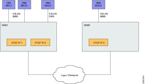
The Virtual Extensible LAN (VXLAN) technology enables you to create virtual domains by running a Layer 2 overlay network on top of Layer 3 with MAC-in-UDP encapsulation and a 24-bit VXLAN ID. The original Layer 2 frame from a Virtual Machine (VM) is encapsulated from within the Virtual Ethernet Module (VEM). Each VEM is assigned at least one IP address that is used as the source IP address when the encapsulated MAC frames are sent to other VEMs over the network.
The IP addresses, which are known as VXLAN Tunnel End Point (VTEP) IP addresses, are assigned to selected interfaces on the corresponding VEM. The encapsulation carries the VXLAN ID to scope the MAC address of the payload frame. The VM's VXLAN ID is indicated within the port profile configuration of the vNIC and is applied when the VM connects to the network.
A VXLAN supports two different modes for flood traffic:
- Multicast mode—A VXLAN uses an IP multicast network to send broadcast, multicast, and unknown unicast flood frames. Each multicast mode VXLAN has an assigned multicast group IP address. When a new VM is deployed on a host in a multicast mode VXLAN, a VEM joins the assigned multicast group IP address by sending IGMP join messages. Flood traffic, broadcast, multicast and unknown unicast from the VM is encapsulated and is sent using the assigned multicast group IP address as the destination IP address. Packets sent to known unicast MAC addresses are encapsulated and sent directly to the destination server VTEP IP addresses. When an encapsulated packet is received from the network, it is decapsulated. Tthe source MAC address of the inner frame and VXLAN ID are added to the Layer 2 table as the lookup key, and the source IP address of the encapsulation header is added as the remote IP address for the table entry.
- Unicast-only mode—The unicast-only mode is a mechanism to support traditional broadcast domain environment without the multicast mode requirement on the physical infrastructure. The packet path functions in the same way as multicast mode, except for the handling of flooded packets (for example, unknown unicast, multicast, and broadcast). A VXLAN uses each VEM's single unicast IP address as the destination IP address to send broadcast, multicast, and unknown unicast flood frames. The frames contain the designated VTEP of each VEM that has at least one VM in the corresponding VXLAN. When a new VM is deployed on the host in a unicast-mode VXLAN, a designated VTEP is selected for receiving flood traffic on that host. This designated VTEP is communicated to all other hosts through the Virtual Supervisor Module (VSM). Flood traffic (broadcast, multicast, and unknown unicast) is replicated on each VEM's designated VTEP in that VXLAN by encapsulating it with a VXLAN header. Packets are sent only to VEMs with a VM in that VXLAN. Packets that have a known unicast MAC address are encapsulated and sent directly to the destination server's VTEP IP address.
- VXLAN Tunnel Endpoints
- Multicast Mode
- Unicast-only Mode
- Fragmentation
- Jumbo Frames
- VXLAN Feature Disabled
VXLAN Tunnel Endpoints
Each VEM requires at least one IP/MAC address pair to terminate VXLAN packets. This IP/MAC address pair is known as the VXLAN Tunnel End Point (VTEP) IP/MAC addresses. The VEM supports IPv4 addressing for this purpose. You configure an interface as a VTEP in interface configuration mode using the capability vxlan command. You can have a maximum of four VTEPs in a single VEM.
One VTEP per VXLAN segment is designated to receive all broadcast, multicast, and unknown unicast flood traffic for the VEM.
When encapsulated traffic is destined to a VEM that is connected to a different subnet, the VEM does not use the VMware host routing table. Instead, the VTEPs initiate the ARP for remote VEM VTEP IP addresses. If the VTEPs in the different VEMs are in different subnets, you must configure the upstream router to respond by using the Proxy ARP.
When encapsulated traffic is destined to a VEM that is connected to a different subnet, the VEM does not use the Linux host routing table. Instead, it can use either Proxy Address Resolution Protocol (ARP) or a default gateway.
- To use Proxy ARP, you must configure the upstream router for Proxy ARP. The VTEPs initiate the ARP for remote VEM VTEP IP addresses. If the VTEPs in the different VEMs are in different subnets, the upstream router can respond using Proxy ARP.
- To use a default gateway, you must configure the VTEP with the transport ip address external command to specify the netmask and gateway IP address for the VTEP to use. For example, from the interface command mode, enter transport ip address external netmask 255.255.255.0 gateway 1.2.3.4.
Multicast Mode
When a VM attaches to a VEM, if it is the first to join the particular VXLAN segment on the VEM, an IGMP Join is issued for the VXLAN’s assigned multicast group. When the VM transmits a packet on the network segment, a lookup is made in the L2 table using the destination MAC of the frame and the VXLAN identifier. If the result is a hit, the L2 table entry will contain the remote IP address to use to encapsulate the frame and the frame will be transmitted within an IP packet destined to the remote IP address. If the result is a miss (broadcast/multicast/unknown unicasts fall into this bucket), the frame is encapsulated with the destination IP address set to be the VXLAN segment’s assigned IP multicast group.
When an encapsulated packet is received from the network, it is decapsulated and the source MAC address of the inner frame and VXLAN ID, is added to the L2 table as the lookup key and the source IP address of the encapsulation header will be added as the remote IP address for the table entry.
Unicast-only Mode
The unicast-only mode is a mechanism to support traditional broadcast domain environment without the multicast mode requirement on the physical infrastructure. The packet path functions in the same way as multicast mode, except for the handling of flooded packets (for example, unknown unicast, multicast, and broadcast). Each host understands all the VXLAN Tunnel End Points (VTEPs) of a VXLAN through the Virtual Supervisor Module (VSM) and the source host makes multiple encapsulated copies of the packet, one for each VTEP that is an active member of the VXLAN.
Fragmentation
The VXLAN encapsulation overhead is 50 bytes. In order to prevent performance degradation due to fragmentation, the entire interconnection infrastructure between all VEMs that exchange VXLAN packets must be configured to carry 50 bytes more than what the VM VNICs are configured to send. For example, if the default VNIC configuration is 1500 bytes, the VEM uplink port profile, upstream physical switch port, and interswitch links, and any routers if present, must be configured to carry a maximum transmission unit (MTU) of at least 1550 bytes. If that is not possible, we recommend that you configure the MTU within the guest VMs to be smaller by 50 bytes.
If you do not configure a smaller MTU, the VEM attempts to notify the VM if it performs Path MTU (PMTU) Discovery. If the VM does not send packets with a smaller MTU, the VM fragments the IP packets. Fragmentation occurs only at the IP layer. If the VM sends a frame that is too large, the frame will be dropped after VXLAN encapsulation and if the frame does not contain an IP packet.
Jumbo Frames
Jumbo frames are supported by the Cisco Nexus 1000V if there is space on the frame to accommodate the VXLAN encapsulation overhead of at least 50 bytes, and the physical switch/router infrastructure has the capability to transport these jumbo-sized IP packets.
VXLAN Feature Disabled
As a safety precaution, do not use the no feature segmentation command if there are any ports associated with a VXLAN port profile. You must remove all associations before you can disable this feature. You can use the no feature segmentation command to remove all the VXLAN bridge domain configurations on the Cisco Nexus 1000V.
Information About VXLAN Gateway
VXLAN termination (encapsulation and decapsulation) is supported on virtual switches. As a result, the only endpoints that can connect into VXLANs are VMs that are connected to a virtual switch. Physical servers cannot be in VXLANs and routers or services that have traditional VLAN interfaces cannot be used by VXLAN networks.
One way that VXLANs can interconnect with traditional VLANs is through VM-based virtual Layer 3 routers. For example, you can use a Cisco ASA 1000V router to interconnect traditional VLANs to VXLANs.
Another option is to use a VXLAN gateway. The Cisco Nexus 1000V VXLAN Gateway provides a way to connect a VXLAN segment to a VLAN segment at Layer 2. A logical instance of this gateway is a 2-port Layer 2 learning bridge that connects a particular VXLAN segment to an IEEE 802.1Q VLAN.
The configuration for such VLAN-VXLAN translation/mappings for the VXLAN gateway must be configured from the VSM and must always be a 1:1 mapping for each Layer 2 domain. Each VXLAN gateway can support multiple VLAN-VXLAN mappings.