Configuring IP Services

Table Of Contents

Configuring IP Services

Traffic Management Services

Management Interface Configuration

Default Gateway

About the Default Gateway

Configuring the Default Gateway

Verifying the Default Gateway Configuration

IPv4 Default Network Configuration

IPFC

IPFC Configuration Guidelines

Configuring an IPv4 Address in a VSAN

Verifying the VSAN Interface Configuration

Enabling IPv4 Routing

Verifying the IPv4 Routing Configuration

IPFC Configuration Example

IPv4 Static Routes

About IPv4 Static Routes

Configuring IPv4 Static Routes

Verifying IPv4 Static Route Information

Displaying and Clearing ARPs

Overlay VSANs

About Overlay VSANs

Configuring Overlay VSANs

Multiple VSAN Configuration

Virtual Router Redundancy Protocol

About VRRP

Configuring VRRP

Adding and Deleting Virtual Router

Virtual Router Initiation

Adding Virtual Router IP Addresses

Priority for the Virtual Router

Time Interval for Advertisement Packets

Priority Preemption

Virtual Router Authentication

Priority Based on Interface State Tracking

Displaying IPv4 VRRP Information

Displaying IPv6 VRRP Information

Displaying VRRP Statistics

Clearing VRRP Statistics

DNS Server Configuration

Displaying DNS Host Information

Default Settings


Configuring IP Services


Cisco MDS 9000 Family switches can route IP traffic between Ethernet and Fibre Channel interfaces. The IP static routing feature is used to route traffic between VSANs. To do so, each VSAN must be in a different IP subnetwork. Each Cisco MDS 9000 Family switch provides the following services for network management systems (NMSs):

IP forwarding on the out-of-band Ethernet interface (mgmt0) on the front panel of the supervisor modules.

IP forwarding or in-band Fibre Channel interface using the IP over Fibre Channel (IPFC) function—IPFC specifies how IP frames can be transported over Fibre Channel using encapsulation techniques. IP frames are encapsulated into Fibre Channel frames so NMS information can cross the Fibre Channel network without using an overlay Ethernet network.

IP routing (default routing and static routing)—If your configuration does not need an external router, you can configure a default route using static routing.

Switches are compliant with RFC 2338 standards for Virtual Router Redundancy Protocol (VRRP) features. VRRP is a restartable application that provides a redundant, alternate path to the gateway switch.


Note For information about configuring IPv6, see Chapter 46, "Configuring IPv6 for Gigabit Ethernet Interfaces."


This chapter includes the following sections:

Traffic Management Services

Management Interface Configuration

Default Gateway

IPv4 Default Network Configuration

IPFC

IPv4 Static Routes

Overlay VSANs

Multiple VSAN Configuration

Virtual Router Redundancy Protocol

DNS Server Configuration

Default Settings

Traffic Management Services

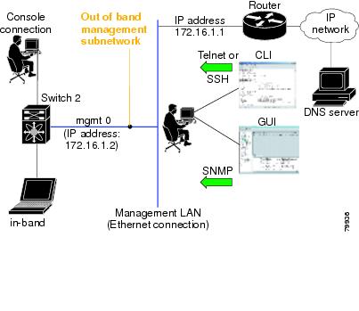
In-band options are compliant with and use the RFC 2625 standards. An NMS host running the IP protocol over an FC interface can access the switch using the IPFC functionality. If the NMS does not have a Fibre Channel HBA, in-band management can still be performed using one of the switches as an access point to the fabric (see Figure 43-1).

Figure 43-1 Management Access to Switches

Management Interface Configuration

The management interface on the switch allows multiple simultaneous Telnet or SNMP sessions. You can remotely configure the switch through the management interface, but first you must configure IP version 4 (IPv4) parameters (IP address, subnet mask) or an IP version 6 (IPv6) address and prefix length so that the switch is reachable. For information on configuring IPv6 addresses, see Chapter 46, "Configuring IPv6 for Gigabit Ethernet Interfaces."

On director class switches, a single IP address is used to manage the switch. The active supervisor module's management (mgmt0) interface uses this IP address. The mgmt0 interface on the standby supervisor module remains in an inactive state and cannot be accessed until a switchover happens. After a switchover, the mgmt0 interface on the standby supervisor module becomes active and assumes the same IP address as the previously active supervisor module.


Note The port on the Ethernet switch to which the MDS management interface is connected should be configured as a host port (also known as access port) instead of a switch port. Spanning tree configuration for that port (on the Ethernet switch) should disabled. This helps avoid the delay in the MDS management port coming up due to delay from Ethernet spanning tree processing that the Ethernet switch would run if enabled. For Cisco Ethernet switches, use either the switchport host command in IOS is or the set port host in Catalyst OS. Refer to the configuration guide for your Ethernet switch.


Note Before you begin to configure the management interface manually, obtain the switch's IP address and IP subnet mask. Also make sure the console cable is connected to the console port.


To configure the mgmt0 Ethernet interface for IPv4, follow these steps:

 
Command
Purpose

Step 1 

switch# config terminal

switch(config)#

Enters configuration mode.

Step 2 

switch(config)# interface mgmt0

switch(config-if)#

Enters the interface configuration mode on the management Ethernet interface (mgmt0).

Step 3 

switch(config-if)# ip address 10.1.1.1 255.255.255.0

Enters the IPv4 address (10.1.1.1) and IPv4 subnet mask (255.255.255.0) for the management interface.

Step 4 

switch(config-if)# no shutdown

Enables the interface.

To configure the mgmt0 Ethernet interface for IPv6, follow these steps:

 
Command
Purpose

Step 1 

switch# config terminal

switch(config)#

Enters configuration mode.

Step 2 

switch(config)# interface mgmt0

switch(config-if)#

Enters the interface configuration mode on the management Ethernet interface (mgmt0).

Step 3 

switch(config-if)# ipv6 address 2001:0db8:800:200c::417a/64

Enters the IPv6 address (2001:0DB8:800:200C::417A) and IPv6 prefix length (/64) for the management interface and enables IPv6 processing on the interface.

switch(config-if)# ipv6 enable

Automatically configures a link-local IPv6 address on the interface and enables IPv6 processing on the interface.

Step 4 

switch(config-if)# no shutdown

Enables the interface.

Default Gateway

You can configure a default gateway IPv4 address on your Cisco MDS 9000 Family switch.

This section includes the following topics:

About the Default Gateway

Configuring the Default Gateway

Verifying the Default Gateway Configuration

About the Default Gateway

The default gateway IPv4 address should be configured along with the IPv4 static routing commands (IP default network, destination prefix, and destination mask, and next hop address).


Tip If you configure the static route IP forwarding and the default-network details, these IPv4 addresses will be used regardless of the default-gateway being enabled or disabled. If these IP addresses are configured but not available, the switch will fall back to using the default gateway IP address, if you have configured it. Be sure to configure IP addresses for all entries in the switch.


See the "Initial Setup Routine" section on page 5-2 for more information on configuring the IP addresses for all entries in the switch.

Use the ip default-gateway command to configure the IP address for a switch's default gateway and the show ip route command to verify that the IPv4 address for the default gateway is configured.

Configuring the Default Gateway

To configure the default gateway, follow these steps:

 
Command
Purpose

Step 1 

switch# config t

switch(config)#

Enters configuration mode.

Step 2 

switch(config)# ip default-gateway 1.12.11.1

Configures the IPv4 address for the default gateway.

Verifying the Default Gateway Configuration

Use the show ip route command to verify the default gateway configuration.

switch# show ip route

Codes: C - connected, S - static

Gateway of last resort is 1.12.11.1

S 5.5.5.0/24 via 1.1.1.1, GigabitEthernet1/1
C 1.12.11.0/24 is directly connected, mgmt0
C 1.1.1.0/24 is directly connected, GigabitEthernet1/1
C 3.3.3.0/24 is directly connected, GigabitEthernet1/6
C 3.3.3.0/24 is directly connected, GigabitEthernet1/5
S 3.3.3.0/24 via 1.1.1.1, GigabitEthernet1/1

IPv4 Default Network Configuration

If you assign the IPv4 default network address, the switch considers routes to that network as the last resort. If the IPv4 default network address is not available, the switch uses the IPv4 default gateway address. For every network configured with the IPv4 default network address, the switch flags that route as a candidate default route, if the route is available.


Tip If you configure the static route IP forwarding and the default network details, these IPv4 addresses will be used regardless of the default gateway being enabled or disabled. If these IPv4 addresses are configured and not available, the switch will fall back to using the default gateway IPv4 address, if you have configured it. Be sure to configure IPv4 addresses for all entries in the switch if you are using IPv4.


See the "Initial Setup Routine" section on page 5-2 for more information on configuring the IP addresses for all entries in the switch.

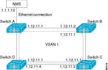
When the Ethernet interface is configured, the switch should point to the gateway router for the IP network. The host accesses the gateway using a gateway switch. This gateway switch is configured as the default gateway. The other switches in the fabric that are connected to the same VSAN as the gateway switch can also be connected through the gateway switch. Every interface connected to this VSAN should be configured with the VSAN IPv4 address of the gateway switch (see Figure 43-2).

Figure 43-2 Overlay VSAN Functionality

In Figure 43-2, switch A has the IPv4 address 1.12.11.1, switch B has the IPv4 address 1.12.11.2, switch C has the IPv4 address 1.12.11.3, and switch D has the IPv4 address 1.12.11.4. Switch A is the gateway switch with the Ethernet connection. The NMS uses the IPv4 address 1.1.1.10 to connect to the gateway switch. Frames forwarded to any switch in the overlaid VSAN 1 are routed through the gateway switch. Configuring the gateway switch's IPv4 address (1.12.11.1) in the other switches enable the gateway switch to forward the frame to the intended destination. Similarly, if a non-gateway switch in the VSAN forwards a frame to the Ethernet world, the frame is routed through the gateway switch.

When forwarding is disabled (default), IP frames are not sent from one interface to another. In these cases, the software performs local IP routing between two switches using the in-band option for Fibre Channel traffic and the mgmt0 option for Ethernet traffic.

When a VSAN is created, a VSAN interface is not created automatically. You need to specifically create the interface (see the "VSAN Interfaces" section on page 12-39).

To configure default networks using IPv4 addresses, follow these steps:

 
Command
Purpose

Step 1 

switch# config t

Enters configuration mode.

Step 2 

switch(config)# ip default-network 190.10.1.0

Configures the IPv4 address for the default network (190.10.1.0).

switch(config)# ip route 10.0.0.0 255.0.0.0 131.108.3.4

switch(config)# ip default-network 10.0.0.0

Defines a static route to network 10.0.0.0 as the static default route.

IPFC

IPFC provides IP forwarding or in-band switch management over a Fibre Channel interface (rather than out-of-band using the Gigabit Ethernet mgmt 0 interface). You can be use IPFC to specify that IP frames can be transported over Fibre Channel using encapsulation techniques. IP frames are encapsulated into Fibre Channel frames so NMS information can cross the Fibre Channel network without using an overlay Ethernet network.

Once the VSAN interface is created, you can specify the IP address for that VSAN. You can assign an IPv4 address or an IPv6 address.


Note See the Chapter 46, "Configuring IPv6 for Gigabit Ethernet Interfaces" for information about configuring IPv6 on the Cisco MDS 9000 Family switches.


This topic includes the following sections:

IPFC Configuration Guidelines

Configuring an IPv4 Address in a VSAN

Verifying the VSAN Interface Configuration

Enabling IPv4 Routing

Verifying the IPv4 Routing Configuration

IPFC Configuration Example

IPFC Configuration Guidelines

Follow these guidelines to configure IPFC:

1. Create the VSAN to use for in-band management, if necessary.

2. Configure an IPv4 address and subnet mask for the VSAN interface.

3. Enable IPv4 routing.

4. Verify connectivity.

Configuring an IPv4 Address in a VSAN

To create a VSAN interface and configure an IPv4 address for that interface, follow these steps:

 
Command
Purpose

Step 1 

switch# config t

Enters configuration mode.

Step 2 

switch(config)# interface vsan 10

switch(config-if)#

Configures the interface for the specified VSAN (10).

Step 3 

switch(config-if)# ip address 10.0.0.12 255.255.255.0

Configures the IPv4 address and netmask for the selected interface.

Step 4 

switch(config-if)# no shutdown

Enables the interface.

Verifying the VSAN Interface Configuration

Use the show interface vsan command to verify the configuration of the VSAN interface.


Note You can see the output for this command only if you have previously configured a VSAN interface.


switch# show interface vsan 1
vsan1 is down (Administratively down)
    WWPN is 10:00:00:0c:85:90:3e:85, FCID not assigned
    Internet address is 10.0.0.12/24
    MTU 1500 bytes, BW 1000000 Kbit
    0 packets input, 0 bytes, 0 errors, 0 multicast
    0 packets output, 0 bytes, 0 errors, 0 dropped

Enabling IPv4 Routing

By default, the IPv4 routing feature is disabled in all switches.

To enable the IPv4 routing feature, follow these steps:

 
Command
Purpose

Step 1 

switch# config t

Enters configuration mode.

Step 2 

switch(config)# ip routing

Enables IPv4 routing (disabled by default).

Step 3 

switch(config)# no ip routing

Disables IPv4 routing and reverts to the factory settings.

Verifying the IPv4 Routing Configuration

Use the show ip routing command to verify the IPv4 routing configuration.

switch(config)# show ip routing
ip routing is enabled

IPFC Configuration Example

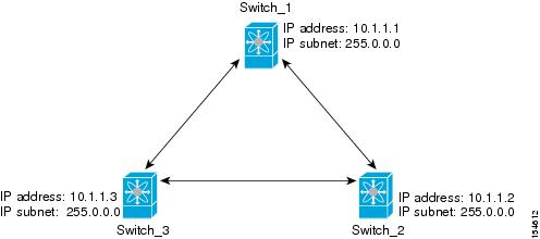
This section describe an example configuration for IPFC. Figure 43-3 shows an example network.

The example network has the following links:

Switch_1 is connected to the main network by the mgmt 0 interface and to the fabric by an ISL.

Switch_2 and Switch_3 are connected to the fabric by an ISL but are not connected to the main network.

Figure 43-3 IPFC Example Network

The following steps show how to configure Switch_1 in the example network in Figure 43-3:


Step 1 Create the VSAN interface and enter interface configuration submode.

switch_1# config t
switch_1(config)# interface vsan 1
switch_1(config-if)#

Step 2 Configure the IP address and subnet mask.

switch_1(config-if)# ip address 10.1.1.1 255.0.0.0

Step 3 Enable the VSAN interface and exit interface configuration submode.

switch_1(config-if)# no shutdown
switch_1(config-if)# exit
switch_1(config)#

Step 4 Enable IPv4 routing.

switch_1(config)# ip routing
switch_1(config)# exit
switch_1#

Step 5 Display the routes.

switch_1# show ip route

Codes: C - connected, S - static

C 172.16.1.0/23 is directly connect, mgmt0
C 10.0.0.0./8 is directly connected, vsan1


The following steps show how to configure Switch_2 in the example network in Figure 43-3.


Step 1 Disable the mgmt 0 interface.


Note Configure this switch using the console connection.


switch_2# config t
switch_2(config)# interface mgmt 0
switch_2(config-if)# no shutdown
switch_2(config-if)# exit
switch_2(config)#

Step 2 Create the VSAN interface and enter interface configuration submode.

switch_2# config t
switch_2(config)# interface vsan 1
switch_2(config-if)#

Step 3 Configure the IP address and subnet mask.

switch_2(config-if)# ip address 10.1.1.2 255.0.0.0

Step 4 Enable the VSAN interface and exit interface configuration submode.

switch_2(config-if)# no shutdown
switch_2(config-if)# exit
switch_2(config)#

Step 5 Enable IPv4 routing.

switch_2(config)# ip routing
switch_2(config)# exit
switch_2#

Step 6 Display the routes.

switch_2# show ip route

Codes: C - connected, S - static

C 10.0.0.0./8 is directly connected, vsan1

Step 7 Verify the connectivity to Switch_1.

switch_2# ping 10.1.1.1
PING 10.1.1.1 (10.1.1.1) 56(84) bytes of data.
64 bytes from 10.1.1.1: icmp_seq=1 ttl=64 time=0.618 ms
64 bytes from 10.1.1.1: icmp_seq=2 ttl=64 time=0.528 ms
64 bytes from 10.1.1.1: icmp_seq=3 ttl=64 time=0.567 ms

--- 10.1.1.1 ping statistics ---
3 packets transmitted, 3 received, 0% packet loss, time 4998 ms
rtt min/avg/max/mdev = 0.528/0.570/0.618/0.057 ms


The following steps show how to configure Switch_3 in the example network in Figure 43-3.


Step 1 Disable the mgmt 0 interface.


Note Configure this switch using the console connection.


switch_3# config t
switch_3(config)# interface mgmt 0
switch_3(config-if)# no shutdown
switch_3(config-if)# exit
switch_3(config)#

switch_3# config t
switch_3(config)# interface vsan 1
switch_3(config-if)#

Step 2 Configure the IP address and subnet mask.

switch_3(config-if)# ip address 10.1.1.3 255.0.0.0

Step 3 Enable the VSAN interface and exit interface configuration submode.

switch_3(config-if)# no shutdown
switch_3(config-if)# exit
switch_3(config)#

Step 4 Enable IPv4 routing.

switch_3(config)# ip routing
switch_3(config)# exit
switch_3#

Step 5 Display the routes.

switch_3# show ip route

Codes: C - connected, S - static

C 10.0.0.0./8 is directly connected, vsan1

Step 6 Verify the connectivity to Switch_1.

switch_3# ping 10.1.1.1
PING 10.1.1.1 (10.1.1.1) 56(84) bytes of data.
64 bytes from 10.1.1.1: icmp_seq=1 ttl=64 time=1.19 ms
64 bytes from 10.1.1.1: icmp_seq=2 ttl=64 time=0.510 ms
64 bytes from 10.1.1.1: icmp_seq=3 ttl=64 time=0.653 ms

--- 10.1.1.1 ping statistics ---
3 packets transmitted, 3 received, 0% packet loss, time 2008 ms
rtt min/avg/max/mdev = 0.510/0.787/1.199/0.297 ms

IPv4 Static Routes

If your network configuration does not need an external router, you can configure IPv4 static routing on your MDS switch.


Note For information about IPv6 static routing, see the "Configuring IPv6 for Gigabit Ethernet Interfaces" section on page 46-1.


This section includes the following topics:

About IPv4 Static Routes

Configuring IPv4 Static Routes

Verifying IPv4 Static Route Information

Displaying and Clearing ARPs

About IPv4 Static Routes

Static routing is a mechanism to configure IPv4 routes on the switch. You can configure more than one static route.

If a VSAN has multiple exit points, configure static routes to direct traffic to the appropriate gateway switch. IPv4 routing is disabled by default on any gateway switch between the out-of-band management interface and the default VSAN, or between directly connected VSANs.

Configuring IPv4 Static Routes

To configure an IPv4 static route, follow these steps:

 
Command
Purpose

Step 1 

switch# config t

Enters configuration mode.

Step 2 

switch(config)# ip route <network IP address> <netmask> <next hop IPv4 address> distance <number> interface <vsan number>


For example:

switch(config)# ip route 10.0.0.0 255.0.0.0 20.20.20.10 distance 10 interface vsan 1

switch(config)#

Configures the static route for the specified IPv4 address, subnet mask, next hop, distance, and interface.

Verifying IPv4 Static Route Information

Use the show ip route command to verifying the IPv4 static route configuration.

switch# show ip route configured
Destination          Gateway             Mask Metric        Interface

         default      172.22.95.1          0.0.0.0      0            mgmt0
        10.1.1.0          0.0.0.0    255.255.255.0      0            vsan1
     172.22.95.0          0.0.0.0    255.255.255.0      0            mgmt0

Use the show ip route command to verifying the active and connected IPv4 static route.

switch# show ip route

Codes: C - connected, S - static

Default gateway is 172.22.95.1

C 172.22.95.0/24 is directly connected, mgmt0
C 10.1.1.0/24 is directly connected, vsan1

Example 43-1 Displays the IP Routing Status

switch# show ip routing
ip routing is disabled

Displaying and Clearing ARPs

Address Resolution Protocol (ARP) entries in Cisco MDS 9000 Family switches can be displayed, deleted, or cleared. The ARP feature is enabled on all switches.

Use the show arp command to display the ARP table.

switch# show arp
Protocol Address           Age (min)  Hardware Addr  Type  Interface
Internet  171.1.1.1               0  0006.5bec.699c  ARPA  mgmt0
Internet  172.2.0.1               4  0000.0c07.ac01  ARPA  mgmt0

Use the no arp command in configuration mode to remove an ARP entry from the ARP table.

switch(config)# no arp 172.2.0.1

Use the clear arp command to delete all entries from the ARP table. The ARP table is empty by default.

switch# clear arp-cache 

Overlay VSANs

This section describes overlay VSANs and how to configure them.

This section includes the following topics:

About Overlay VSANs

Configuring Overlay VSANs

About Overlay VSANs

VSANs enable deployment of larger SANs by overlaying multiple logical SANs, each running its own instance of fabric services, on a single large physical network. This partitioning of fabric services reduces network instability by containing fabric reconfiguration and error conditions within an individual VSAN. VSANs also provide the same isolation between individual VSANs as physically separated SANs. Traffic cannot cross VSAN boundaries and devices may not reside in more than one VSAN. Because each VSAN runs separate instances of fabric services, each VSAN has its own zone server and can be zoned in exactly the same way as SANs without VSAN capability.

Configuring Overlay VSANs

To configure an overlay VSAN, follow these steps:


Step 1 Add the VSAN to the VSAN database on all switch in the fabric.

Step 2 Create a VSAN interface for the VSAN on all switches in the fabric. Any VSAN interface belonging to the VSAN has an IP address in the same subnet. Create a route to the IPFC cloud on the IP side.

Step 3 Configure a default route on every switch in the Fibre Channel fabric pointing to the switch that provides NMS access.

Step 4 Configure the default gateway (route) and the IPv4 address on switches that point to the NMS (see Figure 43-4).

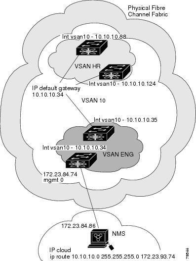
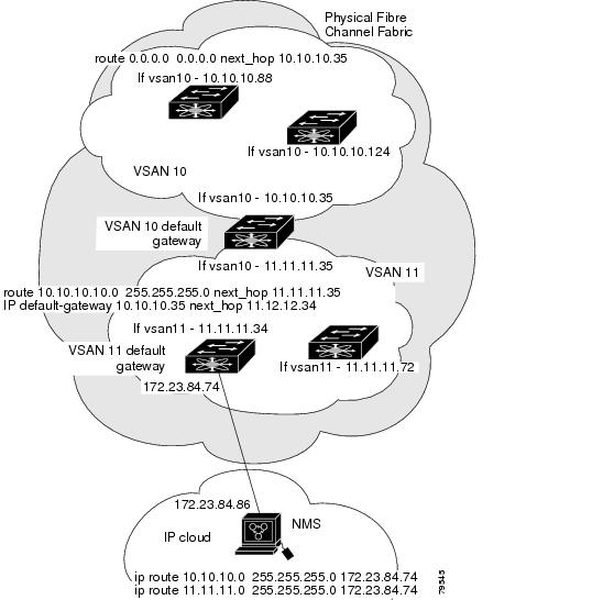
Figure 43-4 Overlay VSAN Configuration Example


Note To configure the management interface displayed in Figure 43-4, set the default gateway to an IPv4 address on the Ethernet network.


The following procedure configures an overlay VSAN in one switch. This procedure must be repeated for each switch in the fabric.

To configure an overlay VSAN in one switch (using the example in Figure 43-4), follow these steps:

 
Command
Purpose

Step 1 

switch# config t

Enters configuration mode.

Step 2 

switch(config)# vsan database

switch-config-vsan-db#

Configures the VSAN database.

Step 3 

switch--config-vsan-db# vsan 10 name MGMT_VSAN

Defines the VSAN in the VSAN database on all of the switches in the Fibre Channel fabric.

Step 4 

switch--config-vsan-db# exit

switch(config)#

Exits the VSAN database mode.

Step 5 

switch(config)# interface vsan 10

switch(config-if)#

Creates a VSAN interface (VSAN 10).

Step 6 

switch(config-if)# ip address 10.10.10.0 netmask 255.255.255.0

Assigns an IPv4 address and subnet mask for this switch.

Step 7 

switch(config-if)# no shutdown

Enables the configured interface.

Step 8 

switch(config-if)# end

switch#

Exits to EXEC mode.

Step 9 

switch# exit

Exits the switch and returns to the NMS. In this example the NMS is assumed to be on the same subnet of the Ethernet management interface of the edge that provides access to the Fibre Channel fabric.

To configure the NMS station displayed in Figure 43-4, follow this step:

 
Command
Purpose

Step 1 

nms# route ADD 10.10.10.0 MASK 255.255.255.0 172.22.93.74

Defines a static route on the NMS pointing to the management interface of the edge switch that provides access to the Fibre Channel fabric.

Multiple VSAN Configuration

More than one VSAN can be used to segment the management network in multiple subnets. An active interface must be present on the switch for the VSAN interface to be enabled.

To configure multiple VSANs, follow these steps:


Step 1 Add the VSAN to the VSAN database on any switch in the fabric.

Step 2 Create a VSAN interface for the appropriate VSAN on any switch in the fabric.

Step 3 Assign an IP address on every VSAN interface on the same subnet as the corresponding VSAN.

Step 4 Define the multiple static routes on the Fibre Channel switches and the IP cloud (see Figure 43-5).

Figure 43-5 Multiple VSAN Configuration Example


To configure an overlay VSAN (using the example in Figure 43-5), follow these steps:

 
Command
Purpose

Step 1 

switch# config t

Enters configuration mode.

Step 2 

switch(config)# vsan database

switch-config-vsan-db#

Configures the VSAN database.

Step 3 

switch-config-vsan-db# vsan 10 name MGMT_VSAN_10

switch-config-vsan-db#

Defines the VSAN in the VSAN database on all of the switches in VSAN 10.

Step 4 

switch-config-vsan-db# exit

switch(config)#

Exits the VSAN database configuration submode.

Step 5 

switch-config-vsan-db# vsan 11 name MGMT_VSAN_11

switch-config-vsan-db#

Defines the VSAN in the VSAN database on all of the switches in VSAN 11.

Step 6 

switch-config-vsan-db# exit

switch(config)#

Exits the VSAN database configuration submode.

Step 7 

switch(config)# interface vsan 10

switch(config-if)#

Enters the interface configuration submode for VSAN 10.

Step 8 

switch(config-if)# ip address 10.10.10.0 netmask 255.255.255.0

switch(config-if)#

Assigns an IPv4 address and subnet mask for this interface.

Step 9 

switch(config-if)# no shutdown

Enables the configured interface for VSAN 10.

Step 10 

switch(config-if)# exit

switch(config)#

Exits the VSAN 10 interface mode.

Step 11 

switch(config)# interface vsan 11

switch(config-if)#

Enters the interface configuration submode for VSAN 11.

Step 12 

switch(config-if)# ip address 11.11.11.0 netmask 255.255.255.0

switch(config-if)#

Assigns an IPv4 address and subnet mask for this interface.

Step 13 

switch(config-if)# no shutdown

Enables the configured interface for VSAN 11.

Step 14 

switch(config-if)# end

switch#

Exits to EXEC mode.

Step 15 

switch# exit

Exits the switch and returns to the NMS. In this example the NMS is assumed to be on the same subnet of the Ethernet management interface of the edge that provides access to the Fibre Channel fabric.

Step 16 

NMS# route ADD 10.10.10.0 MASK 255.255.255.0 172.22.93.74

Defines a static route on the NMS pointing to the management interface of the edge switch that provides access to the IPv4 cloud.

Step 17 

NMS# route ADD 11.11.11.0 MASK 255.255.255.0 172.22.93.74

Defines a static route for VSAN 11 on the NMS pointing to the management interface of the edge switch that provides access to the Fibre Channel fabric.

Step 18 

switch# route 10.10.10.0 255.255.255.0 next_hop 11.11.11.35

Defines the route to reach subnet 10 from subnet 11.

Virtual Router Redundancy Protocol

Cisco MDS 9000 Family switches are compliant with RFC 2338 standards for Virtual Router Redundancy Protocol (VRRP) features. This section provides details on the VRRP feature.

This section includes the following topics:

About VRRP

Configuring VRRP

About VRRP

VRRP provides a redundant alternative path to the gateway switch, which has connectivity to the NMS. VRRP has the following characteristics and advantages:

VRRP is a restartable application.

When a VRRP master fails, the VRRP backup takes over within three times the advertisement time.

VRRP over Ethernet, VRRP over VSAN, and Fibre Channel functions are implemented as defined in RFC 2338 and the draft-ietf-vrrp-ipv6 specification.

A virtual router is mapped to each VSAN and Ethernet interface with its unique virtual router IP, virtual router MAC, and VR ID.

Interface Mgmt 0 supports only one VRRP group. All other interface supports up to 7 virtual router groups, including both IPv4 and IPv6 combined.

VR IDs can be reused in multiple VSANs with different virtual router IP mapping.

Both IPv4 and IPv6 is supported.

The management interface (mgmt 0) supports only one virtual router group. All other interfaces each support up to seven virtual router groups, including both IPv4 and IPv6 combined. Up to 255 virtual router groups can be assigned in each VSAN.

VRRP security provides three options, including no authentication, simple text authentication, and MD5 authentication.


Note If you are using IPv6, you must either configure an IPv6 address on the interface or enable IPv6 on the interface. For more information about IPv6, see Chapter 46, "Configuring IPv6 for Gigabit Ethernet Interfaces."


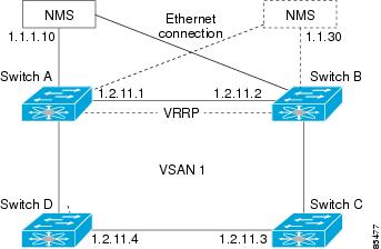
In Figure 43-6, switch A is the VRRP master and switch B is the VRRP backup switch. Both switches have an IP address to VRRP mapping configured. The other switches set switch A as the default gateway. If switch A fails, the other switches do not have to change the routing configurations as switch B automatically becomes the master and takes over the function of a gateway.

Figure 43-6 VRRP Functionality

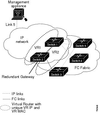
In Figure 43-7, the fabric example has two virtual router groups (VR1 and VR 2) because a virtual router cannot span across different types of interfaces. In both switch 1 and switch 2, the Ethernet interface is in VR 1 and the FC interface is in VR 2. Each virtual router is uniquely identified by the VSAN interface and the VR ID.

Figure 43-7 Redundant Gateway

Configuring VRRP

This section describes how to configure VRRP and includes the following topics:

Adding and Deleting Virtual Router

Virtual Router Initiation

Adding Virtual Router IP Addresses

Priority for the Virtual Router

Time Interval for Advertisement Packets

Priority Preemption

Virtual Router Authentication

Priority Based on Interface State Tracking

Displaying IPv4 VRRP Information

Displaying IPv6 VRRP Information

Displaying VRRP Statistics

Clearing VRRP Statistics

Adding and Deleting Virtual Router

All VRRP configurations should be replicated across switches in a fabric that runs VRRP.


Note The total number of VRRP groups that you can configure on a Gigabit Ethernet port, including main interfaces and subinterfaces, cannot exceed seven. This limitation applies to both IPv4 and IPv6 groups.


To create or remove a VR for IPv4, follow these steps:

 
Command
Purpose

Step 1 

switch# config t

switch(config)#

Enters configuration mode.

Step 2 

switch(config)# interface vsan 10

switch(config-if)#

Configures a VSAN interface (VSAN 10).

Step 3 

switch(config-if)# vrrp 250

switch(config-if-vrrp)#

Creates VR ID 250.

switch(config-if)# no vrrp 250

Removes VR ID 250.

To create or remove a VR for IPv6, follow these steps:

 
Command
Purpose

Step 1 

switch# config t

switch(config)#

Enters configuration mode.

Step 2 

switch(config)# interface vsan 10

switch(config-if)#

Configures a VSAN interface (VSAN 10).

Step 3 

switch(config-if)# vrrp ipv6 250

switch(config-if-vrrp-ipv6)#

Creates VR ID 250.

switch(config-if)# no vrrp ipv6 250

Removes VR ID 250.

Virtual Router Initiation

By default, a virtual router is always disabled. VRRP can be configured only if this state is enabled. Be sure to configure at least one IP address, either IPv4 or IPv6, before attempting to enable a VR.

To enable or disable a virtual router configure for IPv4, follow these steps:

 
Command
Purpose

Step 1 

switch(config-if-vrrp)# no shutdown

Enables VRRP configuration.

switch(config-if-vrrp)# shutdown

Disables VRRP configuration.

To enable or disable a virtual router configured for IPv6, follow these steps:

 
Command
Purpose

Step 1 

switch(config-if-vrrp-ipv6)# no shutdown

Enables VRRP configuration.

switch(config-if-vrrp-ipv6)# shutdown

Disables VRRP configuration.

Adding Virtual Router IP Addresses

One virtual router IP address can be configured for a virtual router. If the configured IP address is the same as the interface IP address, this switch automatically owns the IP address. You can configure either an IPv4 address or an IPv6 address.

According to the VRRP specification, the master VRRP router drops the packets addressed to the virtual router's IP address because the virtual router is only intended as a next-hop router to forward packets. In MDS switches however, some applications require that packets addressed to virtual router's IP address be accepted and delivered to them. By using the secondary option to the virtual router IPv4 address, the VRRP router will accept these packets when it is the master.

To configure an IPv4 address for a virtual router, follow these steps:

 
Command
Purpose

Step 1 

switch# config t

Enters configuration mode.

Step 2 

switch(config)# interface vsan 10

switch(config-if)#

Configures a VSAN interface (VSAN 10).

Step 3 

switch(config-if)# interface ip address 10.0.0.12 255.255.255.0

Configures an IPv4 address and subnet mask. The IPv4 address must be configured before the VRRP is added.

Step 4 

switch(config-if)# vrrp 250

switch(config-if-vrrp)#

Creates VR ID 250.

Step 5 

switch(config-if-vrrp)# address 10.0.0.10

Configures the IPv4 address for the selected VR.

Note This IP v4address should be in the same subnet as the IPv4 address of the interface.

switch(config-if-vrrp)# no address 10.0.0.10

Removes the IP address for the selected VR.

Step 6 

switch(config-if-vrrp)# address 10.0.0.10 secondary

Configures the IP address (10.0.0.10) as secondary for the selected VR.

Note The secondary option should be used only with applications that require VRRP routers to accept the packets sent to the virtual router's IP address and deliver to them. For example, iSNS requires this option (see the "Enabling the iSNS Server" section on page 42-85).

switch(config-if-vrrp)# no address 10.0.0.10 secondary

Removes the IP address (10.0.0.10) as secondary for the selected VR.

To configure an IPv6 address for a virtual router, follow these steps:

 
Command
Purpose

Step 1 

switch# config t

Enters configuration mode.

Step 2 

switch(config)# interface vsan 12

switch(config-if)#

Configures a VSAN interface (VSAN 12).

Step 3 

switch(config-if)# interface ipv6 address 2001:0db8:800:200c::417a/64

Configures an IP address and prefix. The IPv6 address must be configured before the VRRP is added.

Step 4 

switch(config-if)# vrrp ipv6 200

switch(config-if-vrrp-ipv6)#

Creates VR ID 200.

Step 5 

switch(config-if-vrrp-ipv6)# address 2001:0db8:800:200c::417a

Assigns single primary link-local IPv6 address or one of the multiple secondary IPv6 addresses.

Note If this IPv6 address is the same as the physical IPv6 address, this switch is automatically the owner of this IPv6 address.

switch(config-if-vrrp-ipv6)# no address 2001:0db8:800:200c::417a

Removes the IPv6 address for the selected VR.

Priority for the Virtual Router

The valid range to assign a virtual router priority is 1 to 254 with 1 being the lowest priority and 254 being the highest priority. The default value is 100 for switches with secondary IP addresses and 255 for switches with the primary IP address.

To set the priority for a virtual router using IPv4, follow these steps:

 
Command
Purpose

Step 1 

switch# config t

Enters configuration mode.

Step 2 

switch(config)# interface vsan 10

switch(config-if)#

Configures a VSAN interface (VSAN 10).

Step 3 

switch(config-if)# vrrp 250

switch(config-if-vrrp)#

Creates a virtual router.

Step 4 

switch(config-if-vrrp)# priority 2

Configures the priority for the selected VRRP.

Note Priority 255 cannot be preempted.

switch(config-if-vrrp)# no priority

Reverts to the default value (100 for switch with the secondary IPv4 addresses and 255 for switches with the primary IPv4 address).

To set the priority for a virtual router using IPv6, follow these steps:

 
Command
Purpose

Step 1 

switch# config t

Enters configuration mode.

Step 2 

switch(config)# interface vsan 12

switch(config-if)#

Configures a VSAN interface (VSAN 12).

Step 3 

switch(config-if)# vrrp ipv6 200

switch(config-if-vrrp-ipv6)#

Creates a virtual router.

Step 4 

switch(config-if-vrrp-ipv6)# priority 2

Configures the priority for the selected VRRP.

Note Priority 255 cannot be preempted.

switch(config-if-vrrp-ipv6)# no priority

Reverts to the default value (100 for switch with the secondary IPv6 addresses and 255 for switches with the primary IPv6 address).

Time Interval for Advertisement Packets

The valid time range for an advertisement packet on an interface using IPv4 is between 1 and 255 seconds. The default value is 1 (one) second. If the switch has the primary IP address, this time must be specified.

To set the time interval for advertisement packets for a virtual router using IPv4, follow these steps:

 
Command
Purpose

Step 1 

switch# config t

Enters configuration mode.

Step 2 

switch(config)# interface vsan 10

switch(config-if)#

Configures a VSAN interface (VSAN 10).

Step 3 

switch(config-if)# vrrp 50

switch(config-if-vrrp)#

Creates a virtual router.

Step 4 

switch(config-if-vrrp)# advertisement-interval 15

Sets the interval time in seconds between sending advertisement frames. The range is 1 to 255.

switch(config-if-vrrp)# no advertisement-interval

Reverts to the default value (1 second).

To set the time interval for advertisement packets for a virtual router using IPv6, follow these steps:

 
Command
Purpose

Step 1 

switch# config t

Enters configuration mode.

Step 2 

switch(config)# interface vsan 12

switch(config-if)#

Configures a VSAN interface (VSAN 12).

Step 3 

switch(config-if)# vrrp ipv6 200

switch(config-if-vrrp-ipv6)#

Creates a virtual router.

Step 4 

switch(config-if-vrrp-ipv6)# advertisement-interval 150

Sets the interval time in centiseconds between sending advertisement frames. The range is 100 to 4095. The default is 100 centiseconds.

switch(config-if-vrrp-ipv6)# no advertisement-interval

Reverts to the default value (100 centiseconds).

Priority Preemption

You can enable a higher priority backup virtual router to preempt the lower priority master virtual router.


Note If the virtual IP address is also the IP address for the interface, then preemption is implicitly applied.


Note The VRRP preemption is not supported on IP storage Gigabit Ethernet interfaces.


To enable or disable preempting when using IPv4, follow these steps:

 
Command
Purpose

Step 1 

switch# config t

Enters configuration mode.

Step 2 

switch(config)# interface vsan 10

switch(config-if)#

Configures a VSAN interface (VSAN 10).

Step 3 

switch(config-if)# vrrp 250

switch(config-if-vrrp)#

Creates a virtual router.

Step 4 

switch(config-if-vrrp)# preempt

Enables the higher priority backup virtual router to preempt the lower priority master virtual router.

Note This preemption does not apply to the primary IP address.

switch(config-if-vrrp)# no preempt

Disables (default) the preempt option and allows the master to keep its priority level.

To enable or disable preempting when using IPv6, follow these steps:

 
Command
Purpose

Step 1 

switch# config t

Enters configuration mode.

Step 2 

switch(config)# interface vsan 12

switch(config-if)#

Configures a VSAN interface (VSAN 12).

Step 3 

switch(config-if)# vrrp ipv6 200

switch(config-if-vrrp-ipv6)#

Creates a virtual router.

Step 4 

switch(config-if-vrrp-ipv6)# preempt

Enables the higher priority backup virtual router to preempt the lower priority master virtual router.

Note This preemption does not apply to the primary IP address.

switch(config-if-vrrp-ipv6)# no preempt

Disables (default) the preempt option and allows the master to keep its priority level.

Virtual Router Authentication

VRRP security provides three options, including simple text authentication, MD5 authentication, and no authentication.

Simple text authentication uses a unique, 1 to 8 character password that is used by all switches participating in the same virtual router. This password should be different from other security passwords.

MD5 authentication uses a unique, 16 character key that is shared by all switches participating in the same virtual router. This secret key is shared by all switches in the same virtual router.

No authentication is the default option.

You can configure the key using the authentication option in the VRRP submode and distribute it using the configuration file. The security parameter index (SPI) settings assigned in this option should be unique for each VSAN.


Note All VRRP configurations must be duplicated.


Note VRRP router authentication does not apply to IPv6.


To set an authentication option for a virtual router, follow these steps:

 
Command
Purpose

Step 1 

switch# config t

Enters configuration mode.

Step 2 

switch(config)# interface vsan 1

switch(config-if)#

Configures a VSAN interface (VSAN 1).

Step 3 

switch(config-if)# vrrp 250

switch(config-if-vrrp)#

Creates a virtual router.

Step 4 

switch(config-if-vrrp)# authentication text password

Assigns the simple text authentication option and specifies the password for this option.

switch(config-if-vrrp)# authentication md5 password2003 spi 0x2003

Assigns the MD5 authentication option and specifies the key and the unique SPI value for this option. The SPI and the valid range is 0x100 to 0xFFFFFFFF.

switch(config-if-vrrp)# no authentication

Assigns the no authentication option, which is the default.

Priority Based on Interface State Tracking

Interface state tracking changes the priority of the virtual router based on the state of another interface in the switch. When the tracked interface is down, the priority reverts to the priority value for the virtual router (see the"Priority for the Virtual Router" section). When the tracked interface is up, the priority of the virtual router is restored to the interface state tracking value. You can track the state of either a specified VSAN interface or the management interface (mgmt 0). The interface state tracking feature is disabled by default.


Note For interface state tracking to function, you must enable preemption on the interface. See the "Priority Preemption" section.


To track the interface priority for a virtual router using IPv4, follow these steps:

 
Command
Purpose

Step 1 

switch# config t

Enters configuration mode.

Step 2 

switch(config)# interface vsan 10

switch(config-if)#

Configures a VSAN interface (VSAN 10).

Step 3 

switch(config-if)# vrrp 250

switch(config-if-vrrp)#

Creates a virtual router.

Step 4 

switch(config-if-vrrp)# preempt

Enables priority preemption.

Step 5 

switch(config-if-vrrp)# track interface mgmt 0 priority 2

Specifies the priority of the virtual router to be modified based on the state of the management interface.

switch(config-if-vrrp)# no track

Disables the tracking feature.

To track the interface priority for a virtual router using IPv6, follow these steps:

 
Command
Purpose

Step 1 

switch# config t

Enters configuration mode.

Step 2 

switch(config)# interface vsan 12

switch(config-if)#

Configures a VSAN interface (VSAN 12).

Step 3 

switch(config-if)# vrrp ipv6 200

switch(config-if-vrrp-ipv6)#

Creates a virtual router.

Step 4 

switch(config-if-vrrp-ipv6)# preempt

Enables priority preemption.

Step 5 

switch(config-if-vrrp-ipv6)# track interface mgmt 0 priority 2

Specifies the priority of the virtual router to be modified based on the state of the management interface.

Note You must enable IPv6 on the tracked interface for the priority tracking to take affect (see the "Configuring Basic Connectivity for IPv6" section on page 46-11). If IPv6 is not enabled, the interface state is treated as down by VRRP over IPv6, regardless of the actual state of the interface.

switch(config-if-vrrp-ipv6)# no track

Disables the tracking feature.

Displaying IPv4 VRRP Information

Use the show vrrp vr command to display configured IPv4 VRRP information (see Examples 43-2 to 43-4).

Example 43-2 Displays IPv4 VRRP Configured Information

switch# show vrrp vr 7 interface vsan 2 configuration
vr id 7 configuration
admin state down
priority 100
no authentication
advertisement-Interval 1
preempt yes
tracking interface vsan1 priority 2
protocol IP

Example 43-3 Displays IPv4 VRRP Status Information

switch# show vrrp vr 7 interface vsan 2 status 
vr id 7 status
MAC address 00:00:5e:00:01:07
Operational state: init

Example 43-4 Displays IPv4 VRRP Statistics

switch# show vrrp vr 7 interface vsan 2 statistics 
vr id 7 statistics
Become master 0
Advertisement 0
Advertisement Interval Error 0
Authentication Failure 0
TTL Error 0
Priority 0 Received 0
Priority 0 Sent 0
Invalid Type 0
Mismatch Address List 0
Invalid Authentication Type 0
Mismatch Authentication 0
Invalid Packet Length 0

Displaying IPv6 VRRP Information

Use the show vrrp ipv6 vr command to display configured IPv6 VRRP information (see Example 43-5 through Example 43-9).

Example 43-5 Displays IPv6 VRRP Information

switch# show vrrp ipv6 vr 1
      Interface  VR IpVersion Pri   Time Pre State   VR IP addr
---------------------------------------------------------------------------
        GigE1/5   1   IPv6    100  100cs     master  2004::1
        GigE1/6   1   IPv6    100  100cs     backup  2004::1

Example 43-6 Displays IPv6 VRRP Interface Configuration Information

switch# show vrrp ipv6 vr 1 interface gigabitethernet 1/5 configuration
IPv6 vr id 1 configuration
admin state up
priority 100
associated ip: 2004::1
advertisement-interval 100
preempt no
protocol IPv6

Example 43-7 Displays IPv6 VRRP Interface Status Information

switch# show vrrp ipv6 vr 1 interface gigabitethernet 1/5 status
IPv6 vr id 1 status
MAC address 00:00:5e:00:02:01
Operational state: master
Up time 37 min,  10 sec
Master IP address: fe80::20c:30ff:feda:96dc

Example 43-8 Displays IPv6 VRRP Statistics

switch# show vrrp ipv6 vr 1 interface gigabitethernet 1/5 statistics
IPv6 vr id 1 statistics
Become master 1
Advertisement 0
Advertisement Interval Error 0
TTL Error 0
Priority 0 Received 0
Priority 0 Sent 0
Invalid Type 0
Mismatch Address List 0
Invalid Packet Lenght 0

Displaying VRRP Statistics

Use the show vrrp statistics command to display configured IPv6 VRRP information (see Example 43-9).

Example 43-9 Displays VRRP Cumulative Statistics

switch# show vrrp statistics 
Invalid checksum 0
Invalid version 0
Invalid VR ID 0

Clearing VRRP Statistics

Use the clear vrrp statistics command to clear all the VRRP statistics for all interfaces on the switch (see Example 43-10).

Example 43-10 Clears VRRP Statistics

switch# clear vrrp Statistics 

Use the clear vrrp vr command to clear both the IPv4 and IPv6 VRRP statistics for a specified interface (see Example 43-10).

Example 43-11 Clears VRRP Statistics on a Specified Interface

switch# clear vrrp vr 1 interface vsan 1

Use the clear vrrp ipv4 command to clear all the statistics for the specified IPv4 virtual router (see Example 43-12).

Example 43-12 Clears VRRP IPv4 Statistics on a Specified Interface

switch# clear vrrp ipv4 vr 7 interface vsan 2 

Use the clear vrrp ipv6 command to clear all the statistics for the specified IPv6virtual router (see Example 43-13).

Example 43-13 Clears VRRP IPv6 Statistics on a Specified Interface

switch# clear vrrp ipv6 vr 7 interface vsan 2 

DNS Server Configuration

The DNS client on the switch communicates with the DNS server to perform the IP address-name server correspondence.

The DNS server may be dropped after two attempts because of one of the following reasons:

The IP address or the switch name is wrongly configured.

The DNS server is not reachable because external reasons (reasons beyond our control).


Note When accessing a Telnet host, if the DNS server is not reachable (for any reason) the switch login prompt may take a longer time to appear. If so, verify that the DNS server is accurately configured and reachable.


To configure a DNS server, follow these steps:

 
Command
Purpose

Step 1 

switch# config t

switch(config)#

Enters configuration mode.

Step 2 

switch(config)# ip domain-lookup

Enables the IP Domain Naming System (DNS)-based host name-to-address translation.

switch(config)# no ip domain-lookup

Disables (default) the IP DNS-based host name-to-address translation and reverts to the factory default.

Step 3 

switch(config)# ip domain-name cisco.com

Enables the default domain name feature used to complete unqualified host names. Any IP host name that does not contain a domain name (that is, any name without a dot) will have the dot and cisco.com appended to it before being added to the host table.

switch(config)# no ip domain-name cisco.com

Disables (default) the domain name.

Step 4 

switch(config)# ip domain-list harvard.edu

switch(config)# ip domain-list stanford.edu

switch(config)# ip domain-list yale.edu

Defines a filter of default domain names to complete unqualified host names by using the ip domain-list global configuration command. You can define up to 10 domain names in this filter. To delete a name from a filter, use the no form of this command.

switch(config)# no ip domain-list

Deletes the defined filter and reverts to factory default. No domains are configured by default.

Note If you have not configured a domain list, the domain name that you specified with the ip domain-name global configuration command is used. If you configured a domain list, the default domain name is not used. The ip domain-list command is similar to the ip domain-name command, except that with the ip domain-list command you can define a list of domains, each to be tried in turn.

Step 5 

switch(config)# ip name-server 15.1.0.1 2001:0db8:800:200c::417a

Specifies the first address (15.1.0.1) as the primary server and the second address (2001:0db8:800:200c::417a) as the secondary server. You can configure a maximum of six servers.

switch(config)# no ip name-server

Deletes the configured server(s) and reverts to factory default. No server is configured by default.

Step 6 

Note Alternatively, you can configure the DNS entry using the switch names (instead of IP addresses). The configured switch name automatically looks up the corresponding IP address.

Displaying DNS Host Information

Use the show hosts command to display the DNS configuration (see Example 43-14).

Example 43-14 Displays Configured Host Details

switch# show hosts 

Default domain is cisco.com

Domain list: ucsc.edu harvard.edu yale.edu stanford.edu

Name/address lookup uses domain service

Name servers are 15.1.0.1 15.2.0.0

Default Settings

Table 43-1lists the default settings for DNS features.

Table 43-1 Default DNS Settings 

Parameters
Default

Domain lookup

Disabled.

Domain name

Disabled.

Domains

None.

Domain server

None.

Maximum domain servers

6.


Table 43-2lists the default settings for VRRP features.

Table 43-2 Default VRRP Settings 

Parameters
Default

Virtual router state

Disabled.

Maximum groups per VSAN

255.

Maximum groups per Gigabit Ethernet port

7.

Priority preemption

Disabled.

Virtual router priority

100 for switch with secondary IP addresses.

255 for switches with the primary IP address.

Priority interface state tracking

Disabled.

Advertisement interval

1 second for IPv4.

100 centiseconds for IPv6.