Feedback
Table Of Contents
Displaying Switch Hardware Inventory
Running the CompactFlash CRC Checksum Test On Demand
Enabling and Disabling the Automatic CompactFlash CRC Checksum Test
Setting the CompactFlash CRC Checksum Test Interval
Enabling and Disabling Failure Action at the Failure of a CompactFlash Checksum Test
Displaying the Frequency and Status of the CompactFlash CRC Checksum Test
Updating the CompactFlash Firmware
Updating the CompactFlash Firmware On Demand
Enabling and Disabling the CompactFlash Firmware Update
Setting the CompactFlash Firmware Update Interval
Enabling and Disabling Failure Action at the Failure of a CompactFlash Firmware Update
Displaying the Frequency and Status of CompactFlash Updates
Displaying CompactFlash CRC Test and Firmware Update Statistics
Displaying the Switch Serial Number
Displaying Power Usage Information
Power Supply Configuration Modes
Power Supply Configuration Guidelines
Operational Considerations When Removing Crossbars
Graceful Shutdown of a Crossbar
Backward Compatibility for Generation 1 Modules in Cisco MDS 9513 Directors
Displaying Environment Information
Managing System Hardware
This chapter provides details on how to manage system hardware other than services and switching modules and how to monitor the health of the switch. It includes the following sections:
•
Displaying Switch Hardware Inventory
•
•
•
•
•
Displaying Switch Hardware Inventory
Use the show inventory command to view information on the field replaceable units (FRUs) in the switch, including product IDs, serial numbers, and version IDs. See Example 10-1.
Example 10-1 Displays the Hardware Inventory
switch# show inventoryNAME: "Chassis", DESCR: "MDS 9506 chassis"PID: DS-C9506 , VID: 0.104, SN: FOX0712S00TNAME: "Slot 3", DESCR: "2x1GE IPS, 14x1/2Gbps FC Module"PID: DS-X9302-14K9 , VID: 0.201, SN: JAB081405AFNAME: "Slot 4", DESCR: "2x1GE IPS, 14x1/2Gbps FC Module"PID: DS-X9302-14K9 , VID: 0.201, SN: JAB081605A5NAME: "Slot 5", DESCR: "Supervisor/Fabric-1"PID: DS-X9530-SF1-K9 , VID: 4.0, SN: JAB0747080HNAME: "Slot 6", DESCR: "Supervisor/Fabric-1"PID: DS-X9530-SF1-K9 , VID: 4.0, SN: JAB0746090HNAME: "Slot 17", DESCR: "MDS 9506 Power Supply"PID: DS-CAC-1900W , VID: 1.0, SN: DCA07216052NAME: "Slot 19", DESCR: "MDS 9506 Fan Module"PID: DS-6SLOT-FAN , VID: 0.0, SN: FOX0638S150Use the show hardware command to display switch hardware inventory details. See Example 10-2.
Note
Example 10-2 Displays the Hardware Information
switch# show hardwareCisco Storage Area Networking Operating System (SAN-OS) SoftwareTAC support: http://www.cisco.com/tacCopyright (c) 2003-2004 by Cisco Systems, Inc. All rights reserved.The copyright for certain works contained herein are owned byCisco Systems, Inc. and/or other third parties and are used anddistributed under license.SoftwareBIOS: version 1.0.8loader: version 1.1(0.114)kickstart: version 1.3(4a)system: version 1.3(4a)BIOS compile time: 08/07/03kickstart image file is: bootflash:///boot-17rkickstart compile time: 10/25/2010 12:00:00system image file is: bootflash:///isan-17rsystem compile time: 10/25/2020 12:00:00HardwareRAM 1024592 kBbootflash: 1000944 blocks (block size 512b)slot0: 0 blocks (block size 512b)172.22.90.21 uptime is 7 days 4 hours 48 minute(s) 2 second(s)Last reset at 272247 usecs after Thu Sep 11 21:47:05 1980Reason: Reset Requested by CLI command reloadSystem version: 1.3(4a)This supervisor carries Pentium processor with 1024592 kB of memoryIntel(R) Pentium(R) III CPU at family with 512 KB L2 CacheRev: Family 6, Model 11 stepping 1512K bytes of non-volatile memory.1000944 blocks of internal bootflash (block size 512b)--------------------------------Chassis has 9 slots for Modules--------------------------------Module in slot 1 is emptyModule in slot 2 is emptyModule in slot 3 is emptyModule in slot 4 is emptyModule in slot 5 is okModule type is "Supervisor/Fabric-1"No submodules are presentModel number is DS-X9530-SF1-K9H/W version is 1.0Part Number is 73-7523-06Part Revision is A0Manufacture Date is Year 6 Week 47Serial number is JAB064705E1CLEI code is CNP6NT0AAAModule in slot 6 is emptyModule in slot 7 is emptyModule in slot 8 is emptyModule in slot 9 is empty---------------------------------------Chassis has 2 Slots for Power Supplies---------------------------------------PS in slot A is okPower supply type is "1153.32W 110v AC"Model number is WS-CAC-2500WH/W version is 1.0Part Number is 34-1535-01Part Revision is A0Manufacture Date is Year 6 Week 16Serial number is ART061600USCLEI code isPS in slot B is okPower supply type is "1153.32W 110v AC"Model number is WS-CAC-2500WH/W version is 1.0Part Number is 34-1535-01Part Revision is A0Manufacture Date is Year 5 Week 41Serial number is ART0541003VCLEI code is----------------------------------Chassis has one slot for Fan Module----------------------------------Fan module is okModel number is WS-9SLOT-FANH/W version is 0.0Part Number is 800-22342-01Part Revision isManufacture Date is Year 0 Week 0Serial number isCLEI code isRunning Compact Flash Tests
In Cisco SAN-OS Release 3.1(3), you can run the CompactFlash CRC checksum test to identify if the CompactFlash firmware is corrupted and needs to be updated. By default, the CompactFlash CRC checksum test is enabled to automatically run in the background every seven days (you can change the automatic test interval by using the system health module cf-crc-check frequency command in configuration mode). You can run the test on demand by using the system health cf-crc-check module CLI command in EXEC mode. To turn the automatic testing off, use the no system health module cf-crc-check command in configuration mode.
The CompactFlash CRC checksum test can check if CompactFlash is corrupted on the following modules:
•
•
•
•
•
•
This section includes the following tasks:
•
•
•
•
•
Running the CompactFlash CRC Checksum Test On Demand
To run the CompactFlash CRC checksum test, use the system health cf-crc-check module command in EXEC mode.
switch# system health cf-crc-check module numberWhere number indicates the slot in which the identified module resides. For example:
switch(config)# system health cf-crc-check module 4Enabling and Disabling the Automatic CompactFlash CRC Checksum Test
By default, the CompactFlash CRC Checksum test is enabled to automatically run in the background. You can disable the automatic testing and then enable the testing at a later time. You can run the test on demand at any time by using the system health cf-crc-check module command in EXEC mode.
To enable automatic CompactFlash CRC checksum testing, use the system health module cf-crc-check command in configuration mode.
switch# system health module number cf-crc-checkWhere number indicates the slot in which the identified module resides. For example:
switch(config)# system health module 4 cf-crc-checkTo disable automatic CompactFlash CRC checksum testing, use the no system health module cf-crc-check command in EXEC mode.
switch(config)# no system health module number cf-crc-checkSetting the CompactFlash CRC Checksum Test Interval
To set the CompactFlash CRC checksum test interval, use the system health module cf-crc-check frequency command in configuration mode.
To set the CompactFlash CRC checksum test interval, follow these steps:
Enabling and Disabling Failure Action at the Failure of a CompactFlash Checksum Test
You can use the system health module cf-crc-check failure-action command to prevent the Cisco SAN-OS software from taking any action if a CompactFlash failure is determined while running the CRC checksum test and the failed CompactFlash is isolated from further testing. By default, this feature is enabled in all switches in the Cisco MDS 9000 Family. A failure action is controlled at the module level.
Use the system health module cf-crc-check failure-action command in configuration mode to enable the CompactFlash CRC checksum test failure action for a module.
To enable the CompactFlash CRC checksum test failure action, follow these steps:
To disable the CompactFlash CRC checksum test failure action, use the no system health module cf-crc-check failure-action command in configuration mode.
Displaying the Frequency and Status of the CompactFlash CRC Checksum Test
To display the frequency and status of the CompactFlash CRC checksum test for a specific module, use the show system health module command in EXEC mode.
switch# show system health module 5Current health information for module 5.Test Frequency Status Action-----------------------------------------------------------------Bootflash 10 Sec Running EnabledEOBC 5 Sec Running EnabledLoopback 5 Sec Running EnabledCF checksum 1 Day Running EnabledCF re-flash 30 Days Running Enabled-----------------------------------------------------------------Updating the CompactFlash Firmware
In Cisco SAN-OS Release 3.1(3), you can update the CompactFlash firmware on selected modules. By default, the firmware update feature is enabled to automatically update the firmware every 30 days (you can manually set the firmware update intervals by using the system health module cf-re-flash frequency command in configuration mode). You can also update the firmware on demand by using the system health cf-re-flash module command in EXEC mode.
Firmware updates can be enabled on the following modules:
•
•
•
•
•
•
This section includes the following tasks:
•
•
•
•
•
Updating the CompactFlash Firmware On Demand
To update the CompactFlash firmware on demand, use the system health cf-re-flash module command in EXEC mode.
switch# system health cf-re-flash module numberWhere number indicates the slot in which the identified module resides. For example:
switch(config)# system health cf-re-flash module 4Enabling and Disabling the CompactFlash Firmware Update
By default, the CompactFlash firmware is updated automatically every30 days. You can disable the automatic update and then enable the automatic update at a later time. You can update the CompactFlash firmware on demand at any time by using the system health cf-re-flash module command in EXEC mode.
To enable automatic firmware updates, use the system health module cf-re-flash command in configuration mode.
switch(config)# system health module number cf-re-flashWhere number indicates the slot in which the identified module resides. For example:
switch(config)# system health module 4 cf-re-flashTo disable automatic firmware updates, use the no system health module cf-re-flash command in configuration mode.
switch(config)# no system health module number cf-re-flashSetting the CompactFlash Firmware Update Interval
To set the firmware update interval, use the system health module cf-re-flash frequency command in configuration mode. The default interval is every 30 days.
To set the firmware update interval, follow these steps:
Enabling and Disabling Failure Action at the Failure of a CompactFlash Firmware Update
You can use the system health module cf-re-flash failure-action command to prevent the Cisco SAN-OS software from taking any action if a CompactFlash failure is determined while updating the CompactFlash firmware. By default, this action is taken if a failure is determined and the failed CompactFlash is isolated from further testing. A failure action is controlled at the module level.
Use the system health module cf-re-flash failure-action command in configuration mode to enable the CompactFlash firmware update failure action for a module.
To enable the CompactFlash CRC checksum test failure action, follow these steps:
To disable the CompactFlash CRC firmware update test failure action, use the no system health module cf-re-flash failure-action command in configuration mode.
Displaying the Frequency and Status of CompactFlash Updates
To display the frequency and status of the flash updates for a specific module, use the show system health module command in EXEC mode.
switch# show system health module 5Current health information for module 5.Test Frequency Status Action-----------------------------------------------------------------Bootflash 10 Sec Running EnabledEOBC 5 Sec Running EnabledLoopback 5 Sec Running EnabledCF checksum 1 Day Running EnabledCF re-flash 30 Days Running Enabled-----------------------------------------------------------------Displaying CompactFlash CRC Test and Firmware Update Statistics
To display the CompactFlash CRC checksum test and the flash update statistics, use the show system health statistics command in EXEC mode.
switch# show system health statisticsTest statistics for module 2------------------------------------------------------------------------------Test Name State Freqency Run Pass Fail CFail Errs------------------------------------------------------------------------------Bootflash Running 10s 28316 28316 0 0 0EOBC Running 5s 56632 56632 0 0 0Loopback Running 5s 56618 56618 0 0 0CF checksum Running 2d 2 2 0 0 0CF re-flash Running 30d 1 1 0 0 0------------------------------------------------------------------------------Test statistics for module 5------------------------------------------------------------------------------Test Name State Freqency Run Pass Fail CFail Errs------------------------------------------------------------------------------Bootflash Running 10s 28314 28314 0 0 0EOBC Running 5s 56629 56629 0 0 0Loopback Running 5s 56614 56614 0 0 0CF checksum Running 1d 4 4 0 0 0CF re-flash Running 30d 1 1 0 0 0------------------------------------------------------------------------------Test statistics for module 7------------------------------------------------------------------------------Test Name State Freqency Run Pass Fail CFail Errs------------------------------------------------------------------------------InBand Running 5s 56643 56643 0 0 0Bootflash Running 10s 28323 28323 0 0 0EOBC Running 5s 56643 56643 0 0 0Management Port Running 5s 56643 56643 0 0 0------------------------------------------------------------------------------Test statistics for module 8------------------------------------------------------------------------------Test Name State Freqency Run Pass Fail CFail Errs------------------------------------------------------------------------------InBand Running 5s 56624 56624 0 0 0Bootflash Running 10s 28317 28317 0 0 0EOBC Running 5s 56624 56624 0 0 0------------------------------------------------------------------------------Test statistics for module 13------------------------------------------------------------------------------Test Name State Freqency Run Pass Fail CFail Errs------------------------------------------------------------------------------Bootflash Running 10s 28304 28304 0 0 0EOBC Running 5s 56608 56608 0 0 0Loopback Running 5s 56608 56608 0 0 0-------------------------------------------------------------------------------Displaying the Switch Serial Number
The serial number of your Cisco MDS 9000 Family switch can be obtained by looking at the serial number label on the back of the switch (next to the power supply), or by executing the operating system show sprom backplane 1 command.
switch# show sprom backplane 1DISPLAY backplane sprom contents:Common block:Block Signature : 0xababBlock Version : 2Block Length : 156Block Checksum : 0x106fEEPROM Size : 512Block Count : 3FRU Major Type : 0x6001FRU Minor Type : 0x0OEM String : Cisco Systems, Inc.Product Number : DS-C9506Serial Number : FOX0712S007Part Number : 73-8697-01Part Revision : 01Mfg Deviation : 0H/W Version : 0.1Mfg Bits : 0Engineer Use : 0snmpOID : 9.12.3.1.4.26.0.0Power Consump : 0RMA Code : 0-0-0-0Chassis specific block:...
Note
Displaying Power Usage Information
Use the show environment power command to display the actual power usage information for the entire switch. In response to this command, power supply capacity and consumption information is displayed for each module. See Example 10-3.
Note
Example 10-3 Displays Power Management Information
switch# show environment power-----------------------------------------------------PS Model Power Power Status(Watts) (Amp @42V)-----------------------------------------------------1 DS-CAC-2500W 1153.32 27.46 ok2 WS-CAC-2500W 1153.32 27.46 okMod Model Power Power Power Power StatusRequested Requested Allocated Allocated(Watts) (Amp @42V) (Watts) (Amp @42V)--- ------------------- ------- ---------- --------- ---------- ----------1 DS-X9032 199.92 4.76 199.92 4.76 powered-up4 DS-X9032 199.92 4.76 199.92 4.76 powered-up5 DS-X9530-SF1-K9 126.00 3.00 126.00 3.00 powered-up6 DS-X9530-SF1-K9 126.00 3.00 126.00 3.00 powered-up9 DS-X9016 220.08 5.24 220.08 5.24 powered-upPower Usage Summary:--------------------Power Supply redundancy mode: redundantTotal Power Capacity 1153.32 WPower reserved for Supervisor(s)[-] 252.00 WPower reserved for Fan Module(s) [-] 0.00 WPower currently used by Modules[-] 619.92 W-------Total Power Available 281.40 W-------Power Supply Configuration Modes
Switches in the MDS 9000 Family have two redundant power supply slots. The power supplies can be configured in either redundant or combined mode.
•
•
Note
To configure the power supply mode, follow these steps:
Note
Power Supply Configuration Guidelines
Follow these guidelines when configuring power supplies:
1.
a.
For example, suppose you have the following usage figures configured:Power supply 1 = 2500 W
Additional power supply 2 = not used
Current usage = 2000 W
Current capacity = 2500 WThen the following three scenarios differ as specified (see Table 10-1):
Scenario 1: If 1800 W is added as power supply 2, then power supply 2 is shut down.
Reason: 1800 W is less than the usage of 2000 W.Scenario 2: If 2200 W is added as power supply 2, then the current capacity decreases to 2200 W.
Reason: 2200 W is the lesser of the two power supplies.Scenario 3: If 3000 W is added as power supply 2, then the current capacity value remains at 2500 W.
Reason: 2500 W is the lesser of the two power supplies.
Table 10-1 Redundant Mode Power Supply Scenarios
(W)1
2500
2000
1800
2500
Power supply 2 is shut down.
2
2500
2000
2200
2200
Capacity becomes 2200 W.
3
2500
2000
3300
2500
Capacity remains the same.
1 W = Watts
b.
For example, suppose you have the following usage figures configured:
Power supply 1 = 2500 W
Additional Power supply 2 = not used
Current Usage = 2000 W
Current capacity = 2500 WThen, the following three scenarios differ as specified (see Table 10-2):
Scenario 1: If 1800 W is added as power supply 2, then the capacity increases to 3600 W.
Reason: 3600 W is twice the minimum (1800 W).Scenario 2: If 2200 W is added as power supply 2, then the current capacity increases to 4400 W.
Reason:4400 W is twice the minimum (2200 W).Scenario 3: If 3000 W is added as power supply 2, then the current capacity increases to 5000 W.
Reason: 5000 W is twice the minimum (2500 W).
Table 10-2 Combined Mode Power Supply Scenarios
(W)
(W)1
2500
2000
1800
3600
Power is never shut down. The new capacity is changed.
2
2500
2000
2200
4400
3
2500
2000
3300
5000
1 W = Watts
2.
Scenario 1: You have the following usage figures configured:
Power supply 1 = 2500 W
Additional Power supply 2 = 1800 W
Current Usage = 2000 W
Current mode = combined mode (so current capacity is 3600 W)You decide to change the switch to redundant mode. Then power supply 2 is shut down.
Reason: 1800 W is the lesser of the two power supplies and it is less than the system usage.
Scenario 2: You have the following usage figures configured:
Power supply 1 = 2500 W
Additional Power supply 2 = 2200 W
Current Usage = 2000 W
Current mode = combined mode (so current capacity is 4400 W).You decide to change the switch to redundant mode. Then the current capacity decreases to 2200 W.
Reason: 2200 W is the lesser of the two power supplies.
Scenario 3: You have the following usage figures configured:
Power supply 1 = 2500 W
Additional Power supply 2 = 1800 W
Current Usage = 3000 W
Current mode = combined mode (so current capacity is 3600 W).You decide to change the switch to redundant mode. Then the current capacity decreases to 2500 W and the configuration is rejected.
Reason: 2500 W is less than the system usage (3000 W).
Table 10-3 Combined Mode Power Supply Scenarios
1
2500
combined
2000
1800
N/A
3600
This is the existing configuration.
2500
N/A
2000
1800
redundant
2500
Power supply 2 is shut down
2
2500
combined
2000
2200
N/A
4400
This is the existing configuration.
2500
N/A
2000
2200
redundant
2200
The new capacity is changed.
3
2500
combined
3000
1800
N/A
3600
This is the existing configuration.
2500
N/A
3000
1800
redundant
N/A
Rejected, so the mode reverts to combined mode.
1 W = Watts
About Crossbar Management
Cisco MDS SAN-OS Release 3.0(1) and later supports two types of hardware for the Cisco MDS 9500 Series Directors: Generation 1 and Generation 2.
Generation 1 consists of all hardware supported by Cisco SAN-OS prior to Release 3.0(1), including the following:
•
•
•
•
•
•
•
•
Generation 2 consists of all new hardware supported by Cisco SAN-OS Release 3.0(1) and later, including the following:
•
•
•
•
•
•
The Cisco MDS 9500 Series Directors running Cisco MDS SAN-OS 3.0(1) or later support the following types of crossbars:
•
•
Operational Considerations When Removing Crossbars
You can mix and match Generation 1 and Generation 2 hardware on the Cisco MDS 9500 Series Directors running Cisco MDS SAN-OS 3.0(1) or later without compromising the integrity and availability of your SANs based on Cisco MDS 9500 Series Directors.
To realize these benefits, you must consider the following operational requirements when removing crossbars for maintenance activities:
•
•
Graceful Shutdown of a Crossbar
You must perform a graceful shutdown of a crossbar (integrated or external) before removing it from the MDS 9500 Series Director.
•
out-of-service xbar slot
Where slot indicates the external crossbar module slot number.
Note
•
out-of-service module slot
Where slot indicates the chassis slot number on either the Supervisor-1 module or the Supervisor-2 module in which the integrated crossbar resides.
Note
Caution
Backward Compatibility for Generation 1 Modules in Cisco MDS 9513 Directors
To provide backward compatibility for a Generation 1 module in a Cisco MDS 9513 chassis, the active and backup Supervisor-2 modules are associated to a specific crossbar module. The Supervisor-2 module in slot 7 is associated with crossbar module 1 and Supervisor-2 module in slot 8 is associated with crossbar module 2. You must plan for the following operational considerations before removing crossbar modules:
•
–
–
–
•
Note
About Module Temperature
Built-in, automatic sensors are provided in all switches in the Cisco MDS 9000 Family to monitor your switch at all times.
Each module (switching and supervisor) has four sensors: 1 (outlet sensor), 2 (intake sensor), 3 (onboard sensor), and 4 (onboard sensor). Each sensor has two thresholds (in degrees Celsius): minor and major.
Note
•
–
–
–
•
–
System messages are displayed.
Call Home alerts are sent (if configured).
SNMP notifications are sent (if configured).
–
If the threshold is exceeded in a switching module, only that module is shut down.
If the threshold is exceeded in an active supervisor module with HA-standby or standby present, only that supervisor module is shut down and the standby supervisor module takes over.
If you do not have a standby supervisor module in your switch, you have an interval of 2 minutes to decrease the temperature. During this interval the software monitors the temperature every five (5) seconds and continuously sends system messages as configured.
Tip
Displaying Module Temperature
Use the show environment temperature command to display temperature sensors for each module (see Example 10-4 and Example 10-5).
Example 10-4 Displays Temperature Information for Generation 1 Hardware
switch# show environment temperature---------------------------------------------------------------Module Sensor MajorThresh MinorThres CurTemp Status(Celsius) (Celsius) (Celsius)---------------------------------------------------------------2 Outlet 75 60 35 ok2 Intake 65 50 33 ok5 Outlet 75 60 44 ok5 Intake 65 50 36 ok6 Outlet 75 60 42 ok6 Intake 65 50 35 ok7 Outlet 75 60 33 ok7 Intake 65 50 30 ok9 Outlet 75 60 34 ok9 Intake 65 50 39 okExample 10-5 Displays Temperature Information for Generation 2 Hardware
switch# show environment temperature---------------------------------------------------------------Module Sensor MajorThresh MinorThres CurTemp Status(Celsius) (Celsius) (Celsius)---------------------------------------------------------------1 Outlet1 75 60 33 ok1 Outlet2 65 50 30 ok1 Intake1 65 50 30 ok1 LcFwdUp 65 50 35 ok1 LcFwdDn 65 50 39 ok1 FC-MAC 65 50 34 ok6 Outlet1 75 60 33 ok6 Outlet2 65 50 30 ok6 Intake1 65 50 30 ok6 Crosbar 65 50 35 ok6 Arbiter 65 50 39 ok6 CPU 65 50 34 okAbout Fan Modules
Hot-swappable fan modules (fan trays) are provided in all switches in the Cisco MDS 9000 Family to manage airflow and cooling for the entire switch. Each fan module contains multiple fans to provide redundancy. The switch can continue functioning in the following situations:
•
•
Tip
The fan status is continuously monitored by the Cisco MDS SAN-OS software. In case of a fan failure, the following action is taken:
•
•
•
Use the show environment fan command to display the fan module status (see Example 10-6).
Example 10-6 Displays Chassis Fan Information
switch# show environment fan------------------------------------------------------Fan Model Hw Status------------------------------------------------------Chassis DS-9SLOT-FAN 1.2 okPS-1 -- -- okPS-2 -- -- absentThe possible Status field values for a fan module on the Cisco MDS 9500 Series switches are as follows:
•
•
•
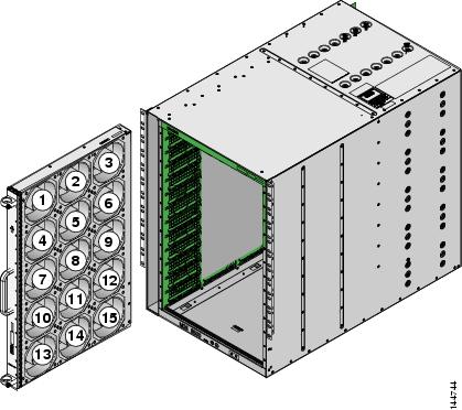
On the Cisco MDS 9513 Director, the front fan module has 15 fans. If the front fan module (DS-13SLT-FAN-F) State field contains "failure" in the show environment fan command output, it also displays the numbers of the failing fans (see Example 10-7).
Example 10-7 Displays Cisco MDS 9513 Front Fan Module Failure
switch# show environment fan------------------------------------------------------Fan Model Hw Status------------------------------------------------------Chassis DS-13SLT-FAN-F 0.3 failure 3 5 6 13Chassis DS-13SLT-FAN-R 0.3 okPS-1 -- -- okPS-2 -- -- okFigure 10-1 shows the numbering of the fans in the front fan module on the Cisco MDS 9513 Director.
Figure 10-1 Cisco MDS 9513 Front Fan Module Numbering
The rear fan module (DS-13SLT-FAN-R) on the Cisco MDS 9513 Director has only two fans. If a fan in the rear fan module fails, the State field in the show environment fan command output only displays "failure" and not the failing fan number (see Example 10-8).
Example 10-8 Displays Cisco MDS 9513 Rear Fan Module Failure
switch# show environment fan------------------------------------------------------Fan Model Hw Status------------------------------------------------------Chassis DS-13SLT-FAN-F 0.3 okChassis DS-13SLT-FAN-R 0.3 failurePS-1 -- -- okPS-2 -- -- okAbout Clock Modules
All switches in the Cisco MDS 9000 Family have two clock modules—Module A (primary) and Module B (redundant). The clock modules are designed, tested, and qualified for mission-critical availability with a mean time between failures (MTBF) of 3,660,316 hours. This translates to a potential failure every 365 years. Additionally, Cisco MDS 9000 Family switches are designed to automatically switch to the redundant clock module should the active clock module fail.
Tip
Use the show environment clock command to display the status for both clock modules (see Example 10-9).
Example 10-9 Displays Chassis Clock Information
switch# show environment clock----------------------------------------------------------Clock Model Hw Status----------------------------------------------------------A DS-C9500-CL 0.0 ok/activeB DS-C9500-CL 0.0 ok/standbyDisplaying Environment Information
Use the show environment command to display all environment-related switch information.
Example 10-10 Displays All Environment Information
switch# show environmentClock:----------------------------------------------------------Clock Model Hw Status----------------------------------------------------------A Clock Module 1.0 ok/activeB Clock Module 1.0 ok/standbyFan:------------------------------------------------------FAN Model Hw Status------------------------------------------------------Chassis DS-2SLOT-FAN 0.0 okPS-1 -- -- okPS-2 -- -- absentTemperature:---------------------------------------------------------------Module Sensor MajorThresh MinorThres CurTemp Status(Celsius) (Celsius) (Celsius)---------------------------------------------------------------1 1 75 60 32 ok1 2 65 50 32 ok1 3 -127 -127 43 ok1 4 -127 -127 39 okPower Supply:-----------------------------------------------------PS Model Power Power Status(Watts) (Amp @42V)-----------------------------------------------------1 PWR-950-AC 919.38 21.89 ok2 -- -- absentMod Model Power Power Power Power StatusRequested Requested Allocated Allocated(Watts) (Amp @42V) (Watts) (Amp @42V)--- ------------------- ------- ---------- --------- ---------- ----------1 DS-X9216-K9-SUP 220.08 5.24 220.08 5.24 powered-upPower Usage Summary:--------------------Power Supply redundancy mode: redundantTotal Power Capacity 919.38 WPower reserved for Supervisor(s)[-] 220.08 WPower reserved for Fan Module(s)[-] 0.00 WPower currently used by Modules[-] 0.00 W-------Total Power Available 699.30 W-------Default Settings
Table 10-4 lists the default hardware settings.