-
Cisco MDS 9000 Family Configuration Guide, Release 1.2(1a)
-
Index
-
Preface
-
Product Overview
-
Before You Begin
-
Initial Configuration
-
Configuring High Availability
-
Software Images
-
Managing Modules
-
Managing System Hardware
-
Configuring and Managing VSANs
-
Configuring Interfaces
-
Configuring Trunking
-
Configuring PortChannels
-
Configuring and Managing Zones
-
Managing FLOGI, Name Server, and RSCN Databases
-
Configuring System Security and AAA Services
-
Configuring Port Security
-
Configuring Fibre Channel Routing Services and Protocols
-
Configuring IP Services
-
Configuring IP Storage
-
Configuring Call Home
-
Configuring Domain Parameters
-
Configuring Traffic Management
-
Configuring System Message Logging
-
Discovering SCSI Targets
-
Monitoring Network Traffic Using SPAN
-
Advanced Features and Concepts
-
Configuring Fabric Configuration Servers
-
Monitoring System Processes and Logs \r\n
-
 Feedback
Table Of Contents
Configuring 32-port Switching Modules and Oversubscribed Ports
About PortChanneling and Trunking
Adding Interfaces to a PortChannel
Deleting Interfaces from a PortChannel
Considerations for PortChannel Configurations
Viewing PortChannel Information
Configuring PortChannels
PortChannels refer to the aggregation of multiple physical interfaces into one logical interface to provide higher aggregated bandwidth, load balancing, and link redundancy. PortChannels can connect to interfaces across switching modules, so a failure of a switching module cannot bring down the PortChannel link. Specifically, a PortChannel has the following functionality:
•
Provides a point-to-point connection over an ISL (E ports) or EISL (TE ports). Multiple links can be combined into a PortChannel.
•
•
•
Note
Cisco MDS 9000 Family of switches support 128 PortChannels with 16 interfaces per PortChannel.
This chapter discusses the PortChannel feature provided in the switch. This chapter includes the following sections:
•
•
•
•
•
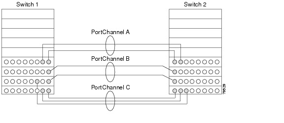
PortChannel Examples
PortChannels on Cisco MDS 9000 Family switches allow flexibility in configuration. Figure 11-1 illustrates three possible PortChannel configurations:
•
•
•
Figure 11-1 PortChannel Flexibility
Configuring 32-port Switching Modules and Oversubscribed Ports
The 32-port 1/2-Gbps switching module contains 8 port groups of 4 ports each. When configuring these modules or the oversubscribed ports in the Cisco 9100 Series, the following guidelines apply:
•
•
–
–
Note
About PortChanneling and Trunking
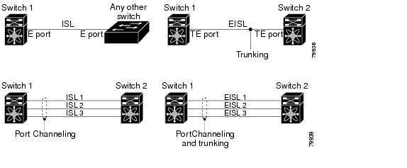
PortChanneling enables several links to be combined into one aggregated link.
Trunking enables an ISL to carry (trunk) multiple VSANs. Trunking can only be configured on a TE port. A TE port is specific to switches in the Cisco MDS 9000 Family. An industry standard E port can link to other vendor switches and is referred to as a nontrunking interface (see Figure 11-2).
See "Configuring Trunking" for information on trunked interfaces.
Figure 11-2 PortChanneling and Trunking
PortChanneling and trunking are used separately across an ISL:
•
•
See "Configuring and Managing VSANs."
Both PortChanneling and trunking can be used between TE ports over EISLs.
About Load Balancing
Two mechanisms support the load balancing functionality:
•
•
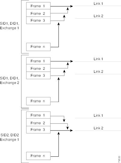
Figure 11-3 illustrates how source ID 1 (SID1) and destination ID1-based(DID1) load balancing works. When the first frame in a flow is received on an interface for forwarding, link 1 is selected. Each subsequent frame in that flow is sent over the same link. No frame in SID1 and DID1 utilizes link 2.
Figure 11-3 SID1 and DID1Based Load Balancing
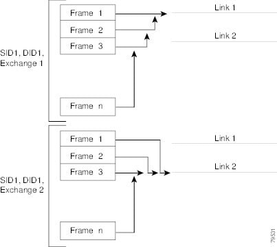
Figure 11-4 illustrates how exchange based load balancing works. When the first frame in an exchange is received for forwarding on an interface, link 1 is chosen by a hash algorithm. All remaining frames in that particular exchange are sent on the same link. For exchange 1, no frame uses link 2. For the next exchange, link 2 is chosen by the hash algorithm. Now all frames in exchange 2 use link 2.
Figure 11-4 SID1, DID1, and Exchange Based Load Balancing
For more information on configuring load balancing and in-order delivery features, see the "VSAN Attributes" section.
Creating a PortChannel
You can create PortChannels using the interface port-channel command. PortChannels are created with default values. You can change the default configuration just like any other physical interface.
To create a PortChannel, follow these steps:
Step 1
Enters configuration mode.
Step 2
Configures the specified PortChannel (1).
Note
Deleting a PortChannel
To delete the PortChannel, you must explicitly issue the no interface port-channel command. When you delete the PortChannel, the corresponding channel membership is also deleted. All interfaces in the deleted PortChannel convert to individual physical links. To avoid inconsistent states across switches, and to maintain consistency across switches, the ports shut down. They continue to use the configured values of the physical port.
To delete a PortChannel, follow these steps:
Adding Interfaces to a PortChannel
You can add a physical interface (or a range of interfaces) to a nonexistent or an existing PortChannel and the PortChannel is automatically created. If the PortChannel does not exist, it is created. The compatible parameters on the configuration are mapped to the PortChannel.
To add a port (or a range of ports) to a PortChannel, follow these steps:
Forcing an Interface Addition
You can specify a force option to force the port configuration to be overwritten by the PortChannel. In this case, the interface is added to a PortChannel and the port is shut down.
Note
To force the addition of a port to a PortChannel, follow these steps:
Compatibility Check
A compatibility check ensures that the same configuration values are used in all physical ports in the channel. For example, to enable trunk mode, all operational ports in the configuration must be configured in the trunk mode or in the nontrunking mode. Otherwise, they cannot become part of a PortChannel. A port cannot be operational if it is incompatible with the PortChannel. If the compatibility check is successful, the interfaces are operational and the corresponding states apply to these interfaces.
Suspended State
An interface enters the suspended state if its operational values are incompatible with the PortChannel. A compatibility check on operational parameters is done when one of the following events occurs:
•
•
The software performs a compatibility check on the operational parameters and places the interface in an operational or suspended state based on the result (see the "Reason Codes" section).
Deleting Interfaces from a PortChannel
To delete a physical interface (or a range of physical interfaces), you must explicitly issue the no channel-group command at the physical interface level. When a physical interface is deleted from the PortChannel, the channel membership is automatically updated. If the deleted interface is the last operational interface, then the PortChannel status is changed to a down state. Deleting an interface from a PortChannel decreases the channel size and bandwidth of the PortChannel.
Note
To delete a physical interface (or a range of physical interfaces), follow these steps:
Considerations for PortChannel Configurations
Before configuring a PortChannel, consider the following guidelines
•
•
Error Detection
If you misconfigure PortChannels, you may receive the Error disabled - Possible port channel misconfiguration message. If you receive this message, the PortChannel's physical links are disabled since an error has been detected.
A PortChannel error is detected if the following requirements are not met:
•
•
•
If you change the links after the PortChannel is configured, be sure to reconnect the links to interfaces within the PortChannel and re-enable the links. Issue the show interface command for that interface to verify that the PortChannel is functioning as required.
If all three conditions are not met, the faulty link is disabled.
Viewing PortChannel Information
You can view specific information about existing PortChannels at any time from EXEC mode. The following show commands provide further details on existing PortChannels. You can force all screen output to go to a printer or save it to a file.
The show port-channel summary command displays a summary of PortChannels within the switch. A one-line summary of each PortChannel provides the administrative state, the operational state, the number of attached and active interfaces (up), and the first operational interface (FOP), which is the primary operational interface selected in the PortChannel. See Examples 11-1 to 11-6.
Example 11-1 PortChannel Summary
switch# show port-channel summary
------------------------------------------------------------------------------
Interface Total Ports Oper Ports First Oper Port------------------------------------------------------------------------------port-channel 1 2 2 fc2/3port-channel 2 2 2 fc2/5port-channel 3 2 2 fc2/10. . .Example 11-2 PortChannel Compatibility
switch# show port-channel compatibility-parametersphysical port layer fibre channel or ethernetport mode E/AUTO onlytrunk modespeedport VSANport allowed VSAN listExample 11-3 PortChannel Database
switch# show port-channel database
port-channel 1
Administrative channel mode is onOperational channel mode is onLast membership update succeededFirst operational port is fc2/32 ports in total, 2 ports upPorts: fc2/3 [up]fc2/4 [up]port-channel 2Administrative channel mode is onOperational channel mode is onLast membership update succeededFirst operational port is fc2/52 ports in total, 2 ports upPorts: fc2/5 [up]fc2/6 [up]...The show port-channel consistency command has two options—without detail and detail.
Example 11-4 Command Without Details
switch# show port-channel consistency sup database:================================================totally 7 port-channelsport-channel 1:2 ports, first operational port is fc2/3fc2/3 [up]fc2/4 [up]port-channel 2:2 ports, first operational port is fc2/5fc2/5 [up]fc2/6 [up]...Example 11-5 Command With Details
switch# show port-channel consistency detailAuthoritative port-channel database:================================================totally 7 port-channelsport-channel 1:2 ports, first operational port is fc2/3fc2/3 [up]fc2/4 [up]port-channel 2:2 ports, first operational port is fc2/5fc2/5 [up]fc2/6 [up]...================================================database 1: from module 5================================================totally 7 port-channelsport-channel 1:2 ports, first operational port is fc2/3fc2/3 [up]fc2/4 [up]port-channel 2:2 ports, first operational port is fc2/5fc2/5 [up]fc2/6 [up]...================================================database 3: from module 2================================================totally 7 port-channelsport-channel 1:2 ports, first operational port is fc2/3fc2/3 [up]fc2/4 [up]port-channel 2:2 ports, first operational port is fc2/5fc2/5 [up]fc2/6 [up]...The show port-channel usage command displays details of the used and unused PortChannel numbers.
Example 11-6 PortChannel Usage
switch# show port-channel usage Totally 7 port-channel numbers used===================================Used : 1-7Unused: 8-128Default Settings
Table 11-1 lists the default settings for PortChannels.
Table 11-1 Default PortChannel Parameters
PortChannels
FSPF is enabled by default.
Create PortChannel
Administratively up.
Default mode
Auto.