-
Cisco MDS 9000 Family Configuration Guide, Release 1.0(2a)
-
Index
-
Preface
-
Product Overview
-
Before You Begin
-
Initial Configuration
-
Configuring High Availability
-
Software Images
-
Managing Modules
-
Managing System Hardware
-
Configuring and Managing VSANs
-
Configuring Interfaces
-
Configuring Trunking
-
Configuring PortChannels
-
Configuring and Managing Zones
-
Managing FLOGI, Name Server, and RSCN Databases
-
Configuring System Security and AAA Services
-
Configuring Fibre Channel Routing Services and Protocols
-
Configuring IP Services
-
Configuring Call Home
-
Configuring Domain Parameters
-
Configuring Traffic Management
-
Configuring System Message Logging
-
Discovering SCSI Targets
-
Monitoring Network Traffic Using SPAN
-
Advanced Features and Concepts
-
Configuring Fabric Configuration Servers
-
Monitoring System Processes and Logs
-
 Feedback
Table Of Contents
Configuring Trunk-Allowed VSAN List
Trunking Configuration Guidelines
Displaying Trunking Information
Configuring Trunking
This chapter describes the trunking feature provided in Cisco MDS 9000 switches. It includes the following sections:
•
Configuring Trunk-Allowed VSAN List
•
•
About Trunking
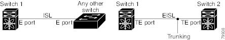
Trunking, also known as VSAN trunking, is a feature specific to switches in the Cisco MDS 9000 Family. Trunking enables interconnect ports to transmit and receive frames in more than one VSAN, over the same physical link, using Extended ISL (EISL) frame format (see Figure 10-1).
Figure 10-1 Trunking
The trunking feature includes the following restrictions:
•
•
•
About Trunking Protocol
The trunking protocol is important for E-port and TE-port operations. It supports the following:
•
•
•
By default, the trunking protocol is enabled. If the trunking protocol is disabled on a switch, no port on that switch can apply new trunk configurations. Existing trunk configurations will not be affected—the TE port continues to function in trunk mode, but only supports traffic in VSANs that it negotiated previously (when the trunking protocol was enabled). Also, other switches that are directly connected to this switch are similarly affected on the connected interfaces. In some cases, you may need to merge traffic from different port VSANs across a non-trunking ISL. If so, you need to disable the trunking protocol.
Tip
To enable or disable the trunking protocol, follow these steps:
Configuring Trunk Modes
By default, the trunk mode is enabled in all Fibre Channel interfaces. However, the trunk mode configuration takes effect only in E-port mode. You can configure the trunk mode as on (enabled), off (disabled), or auto (automatic). The default trunk mode is on. The trunk mode configuration at the two ends of an ISL, between two switches, determine the trunking state of the link and the port modes at both ends (see Table 10-1).
Note
To configure the trunk mode, follow these steps:
Configuring Trunk-Allowed VSAN List
Each Fibre Channel interface has an associated trunk-allowed VSAN list. In TE-port mode, frames are transmitted and received in one or more VSANs specified in this list. By default, the VSAN range (1 through 4093) is included in the trunk-allowed list.
The common set of VSANs that are configured and active in the switch are included in the trunk-allowed VSAN list for an interface, and they are called allowed-active VSANs. The trunking protocol uses the list of allowed-active VSANs at the two ends of an ISL to determine the list of operational VSANs in which traffic is allowed.
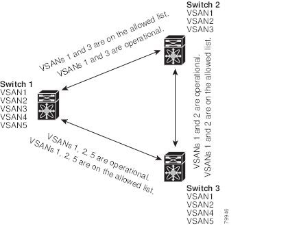
In Figure 10-2, switch 1 has VSANs 1 through 5, switch 2 has VSANs 1 through 3, and switch 3 has VSANs 1, 2, 4, and 5 with a default configuration of trunk-allowed VSANs. All VSANs configured in all three switches are allowed-active. However, only the common set of allowed-active VSANs at the ends of the ISL become operational as shown in Figure 10-2.
Figure 10-2 Default Allowed -Active VSAN Configuration
You can configure a select set of VSANs (from the allowed-active list) to control access to those VSANs in a trunking ISL. Using Figure 10-2 as an example, you can configure the list of allowed VSANs on a per-interface basis (see Figure 10-3).
Figure 10-3 Operational and Allowed VSAN Configuration
In Figure 10-3, the operational allowed list of VSANs between switches is as follows:
•
•
•
Consequently, VSAN 2 can only be routed from switch 1 through switch 3 to switch 2.
To configure an allowed-active list of VSANs for an interface, follow these steps:
Trunking Configuration Guidelines
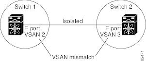
If you misconfigure VSAN configurations across E ports, you could face consequences such as merging the traffic in two VSANs. The trunking protocol validates the VSAN interfaces at both ends of an ISL to avoid VSANs merging (see Figure 10-4).
Figure 10-4 VSAN Mismatch
In this example, the trunking protocol detects potential VSAN merging and isolates the ports involved.
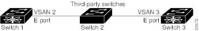
The trunking protocol cannot detect merging of VSANs when a third-party switch is placed in between two Cisco MDS 9000 Family switches (see Figure 10-5).
Figure 10-5 Third-Party Switch VSAN Mismatch
VSANs 2 and 3 get effectively merged with overlapping entries in the name server and the zone applications. The Cisco MDS 9000 Fabric Manager helps detect such topologies (see the Cisco MDS 9000 Family Fabric Manager User Guide).
Displaying Trunking Information
The show interface command is invoked from the EXEC mode and displays trunking configurations for a TE port. Without any arguments, this command displays the information for all of the configured interfaces in the switch. See Examples 10-1 to 10-3.
Example 10-1 Displays a Trunked Fiber Channel Interface
switch# show interface fc1/13fc1/13 is trunkingHardware is Fibre ChannelPort WWN is 20:0d:00:05:30:00:58:1ePeer port WWN is 20:0d:00:05:30:00:59:1eAdmin port mode is auto, trunk mode is onPort mode is TEPort vsan is 1Speed is 2 GbpsReceive B2B Credit is 255Beacon is turned offTrunk vsans (admin allowed and active) (1)Trunk vsans (up) (1)Trunk vsans (isolated) ()Trunk vsans (initializing) ()5 minutes input rate 0 bits/sec, 0 bytes/sec, 0 frames/sec5 minutes output rate 0 bits/sec, 0 bytes/sec, 0 frames/sec233996 frames input, 14154208 bytes, 0 discards0 CRC, 0 unknown class0 too long, 0 too short236 frames output, 13818044 bytes, 0 discards11 input OLS, 12 LRR, 10 NOS, 28 loop inits34 output OLS, 19 LRR, 17 NOS, 12 loop initsExample 10-2 Displays Trunking Protocol
switch# show trunk protocolTrunk protocol is enabledExample 10-3 Displays Per VSAN Information on Trunk Ports
switch# show interface trunk vsan 1-1000fc3/1 is not trunkingfc3/7 is trunkingVsan 1000 is down (Isolation due to vsan not configured on peer)fc3/10 is trunkingVsan 1 is up, FCID is 0x760001Vsan 2 is up, FCID is 0x6f0001fc3/11 is trunkingBelongs to port-channel 6Vsan 1 is up, FCID is 0xef0000Vsan 2 is up, FCID is 0xef0000port-channel 6 is trunkingVsan 1 is up, FCID is 0xef0000Vsan 2 is up, FCID is 0xef0000Default Settings
Table 10-2 lists the default settings for trunking parameters.
Table 10-2 Default Trunk Configuration Parameters
Switch port trunk mode
On
Allowed VSAN list
1 to 4093 user-defined VSAN IDs
Trunking protocol
Enabled