-
User Guide for Cisco Security MARS Local Controller, Release 5.2.x
-
Preface
-
STM Task Flow Overview
-
Reporting and Mitigation Devices Overview
-
Configuring Router and Switch Devices
-
Configuring Firewall Devices
-
Configuring VPN Devices
-
Configuring Network-based IDS and IPS Devices
-
Configuring Host-Based IDS and IPS Devices
-
Configuring Antivirus Devices
-
Configuring Vulnerability Assessment Devices
-
Configuring Generic, Solaris, Linux, and Windows Application Hosts
-
Configuring Database Applications
-
Configuring Web Server Devices
-
Configuring Web Proxy Devices
-
Configuring AAA Devices
-
Configuring Custom Devices
-
Policy Table Lookup on Cisco Security Manager
-
Network Summary
-
Case Management
-
Incident Investigation and Mitigation
-
Queries and Reports
-
Rules
-
Sending Alerts
-
Management Tab Overview
-
System Maintenance
-
Cisco Security MARS XML API Reference
-
Regular Expression Reference
-
Date/Time Format Specfication
-
System Rules and Reports Reference
-
Glossary
-
Index
-
 Feedback
Table Of Contents
Configuring Router and Switch Devices
Enable Administrative Access to Devices Running Cisco IOS 12.2
Enable SNMP Administrative Access
Enable Telnet Administrative Access
Enable SSH Administrative Access
Enable FTP-based Administrative Access
Configure the Device Running Cisco IOS 12.2 to Generate Required Data
Enable SDEE for IOS IPS Software
Add and Configure a Cisco Router in MARS
Enable Communications Between Devices Running CatOS and MARS
Enable SNMP Administrative Access
Enable Telnet Administrative Access
Enable SSH Administrative Access
Enable FTP-based Administrative Access
Configure the Device Running CatOS to Generate Required Data
Enable SNMP RO Strings on CatOS
Enable Syslog Messages on CatOS
Add and Configure a Cisco Switch in MARS
Adding Modules to a Cisco Switch
Add Cisco IOS 12.2 Modules Manually
Configure ExtremeWare to Generate the Required Data
Add and Configure an ExtremeWare Switch in MARS
Add and Configure a Generic Router in MARS
Configuring Router and Switch Devices
This chapter describes how to bootstrap routers and switches and add those reporting devices and mitigation devices to MARS. It also describes how to configure NetFlow, NAC's EAP over UDP and 802.1x logging, and the Layer 2 (L2) mitigation features of switches.
Routers and switches provide MARS with data about traffic flows and the network topology, including address translations, endpoint devices, connected networks, and accepted and rejected sessions. Routers and switches also support modules that enable features common to specialty security appliances, such as firewalls and intrusion detection or prevention systems (IDS/IPS). This chapter does not describe how to enable the features on routers and switches that enable the modules or how to configure these modules for use by MARS. Such discussions are provided in Configuring Firewall Devices, page 4-1, and Configuring Network-based IDS and IPS Devices, page 6-1.
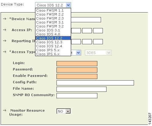
This chapter explains how to bootstrap and add the following router and switch devices to MARS:
Cisco Router Devices
To configure Cisco routers running Cisco IOS Software Release 12.2 to communicate with a MARS Appliance, you must perform three tasks:
•
Enable Administrative Access to Devices Running Cisco IOS 12.2
•
•
Enable Administrative Access to Devices Running Cisco IOS 12.2
You must enable administrative access by the MARS Appliance to any Cisco routers or switches running Cisco IOS Software release 12.2 or later. The type of access that you must enable depends on whether modules are installed in your Cisco router or switch and the role of the device in your network. MARS uses this administrative access to discover the device's configuration and, at times, to make changes to the device's running configuration. For information on selecting an administrative access method, see Selecting the Access Type, page 2-10.
Before you add a Cisco router to MARS, make sure that you have enabled SNMP, Telnet, SSH, or FTP access to the router. The following sections provide guidance on configuring each supported access method:
•
•
•
•
Enable SNMP Administrative Access
To enable configuration discovery using SNMP access to the Cisco router or switch, refer to your device documentation or the following URL:
http://www.cisco.com/en/US/docs/ios/12_3t/12_3t2/feature/guide/gtsnmpal.html#wp1044725
Enable Telnet Administrative Access
To enable configuration discovery using Telnet access to the Cisco router or switch, refer to your device documentation or the following URL:
Enable SSH Administrative Access
To enable configuration discovery using SSH access to the Cisco router or switch, refer to your device documentation or the following URL:
http://www.cisco.com/en/US/docs/ios/12_1t/12_1t3/feature/guide/sshv1c.html#wp1034488
Enable FTP-based Administrative Access
To enable configuration discovery using FTP access, you must place a copy the Cisco router's or switch's configuration file on an FTP server to which the MARS Appliance has access. This FTP server must have user authentication enabled.
Note
You must copy the running configuration from the Cisco router or switch. For information on copying the running configuration, refer to your device documentation or the following URL:
http://www.cisco.com/en/US/products/sw/iosswrel/ps1835/products_tech_note09186a008020260d.shtml
Configure the Device Running Cisco IOS 12.2 to Generate Required Data
Cisco routers and switches that are running Cisco IOS Software release 12.2 can be configured to provide different types of data to MARS:
•
•
•
•
•
The following topics describe how to configure these settings:
•
Enable Syslog Messages
To send syslog messages to the MARS Appliance from a device running Cisco IOS Software Release 12.2, follow these steps:
Step 1
Step 2
Router(config)#logging source-interface <interface name>Router(config)#logging trap <logging level desired>Router(config)#logging <IP address of MARS Appliance>
Enable SNMP RO Strings
To enable SNMP RO strings for topology discovery on the Cisco IOS device, you must enable the SNMP server and define the RO community.
To configure the SNMP RO string settings, follow these steps:
Step 1
Router> enablePassword: <password>Router#Step 2
Router# configure terminalEnter configuration commands, one per line. End with CNTL/Z.Router(config)#Step 3
Router(config)# snmp-server community <read community> RO <ACL name if required>
Note
Step 4
Router(config)# snmp-server community <write community> RWThe Add and Configure a Cisco Router in MARS procedure provides instructions for configuring the MARS Appliance to discover configuration and settings using these strings
Enable NAC-specific Messages
Cisco routers and switches that are running Cisco IOS Software release 12.2 or CatOS can enable network Admission Control (NAC) specific data. This data includes:
•
•
•
For more information on the events that are logged as part of NAC, see the Monitoring and Reporting Tool Integration into Network Admission Control white paper at the following URL:
http://www.cisco.com/en/US/netsol/ns617/networking_solutions_white_paper0900aecd801dee49.shtml
This section contains the following two topics, which address the NAC configuration settings specific to each device type:
Cisco Routers
This command ensures that the IOS device sends the IP address of the host that is being NAC'd in its calling-station-id attribute in all RADIUS requests to the ACS.
To configure the NAC Phase I data on a Cisco router to work with MARS, you must allow EAP over UDP and allow an IP address in the AAA station-id field of the packets. (Cisco Secure ACS includes this detail in its logs. MARS presents this data in reports and queries that dispay the host IP addresses.) In addition, you must enable logging of these events, which are published as syslog messages.
To enable the NAC-specific data on a Cisco router, enter the following commands:
Router(config)#eou allow ip-station-idRouter(config)#eou loggingFor more information on these commands and related commands, see the Network Admission Control feature document at the following URL:
http://www.cisco.com/en/US/docs/ios/12_3t/12_3t8/feature/guide/gt_nac.html
Cisco Switches
NAC Phase II enables Cisco switches to act as network access devices. To support this new feature, you must configure the Cisco switch to initiate 802.1x authentication when the link state changes from down to up and periodically if the port remains up but unauthenticated. NAC requires that hosts use 802.1x supplicants, or clients, to authenticate to the Cisco Secure ACS server before gaining access to network services. Enabling the 802.1x messages on your network helps you troubleshoot supplicant failures becauise connection attempts are logged, which you can analyze.
Configuring the Cisco switch to act as proxy between the Cisco Secure ACS server and the 802.1x supplicants is a multi-step process. First, the e switch must be defined as a AAA client (RADIUS) in the Cisco Secure ACS server. For information on defining a AAA client, see Define AAA Clients, page 14-5. Second, the switch must be configured to use a a RADIUS server. Then, you must enable the following features on each interface installed in the switch:
•
•
•
•
The following URLs detail how to configure these features:
Dot1x and Radius Sever
IOS Software:
CatOS Software: http://www.cisco.com/en/US/docs/switches/lan/catalyst6500/catos/8.x/configuration/guide/8021x.html
DHCP Snooping
IOS Software: http://www.cisco.com/en/US/docs/switches/lan/catalyst3750/software/release/12.2_25_sec/configuration/guide/swdhcp82.html
CatOS Software: http://www.cisco.com/en/US/docs/switches/lan/catalyst6500/catos/8.x/configuration/guide/dhcp.html
After you configure the switch to act as proxy and it is defined as a AAA client in Cisco Secure ACS, you must ensure that the authentication messages are sent to the MARS Appliance. For 802.1x accounting records, you must ensure that the audit records are written to the RADIUS log on the Cisco Secure ACS server. To configure these settings, refer toConfigure Cisco Secure ACS to Generate Logs, page 14-3.
Enable SDEE for IOS IPS Software
Before you enable SDEE, you must enable either Telnet or SSH as the access type for configuration discovery on a Cisco IOS device. You must also enable SDEE on the device that supports the IOS IPS software feature. SDEE is used to publish events to MARS about signatures that have fired.
To enable SDEE protocol on the Cisco IOS device that supports IOS IPS, follow these steps:
Step 1
Step 2
Router(config)#ip http secure-serverRouter(config)#ip ips notify sdeeRouter(config)#ip sdee subscriptions 3Router(config)#ip sdee events 1000Router(config)#no ip ips notify log
Note
Add and Configure a Cisco Router in MARS
Cisco routers provide data about the network and its activities in the form of syslog messages and SNMP RO MIBs. In addition, MARS can discover settings, such as network address translations, attached networks, and active access rules, that improve the accuracy of false positive identification, attack path analysis, and L3 network discovery.
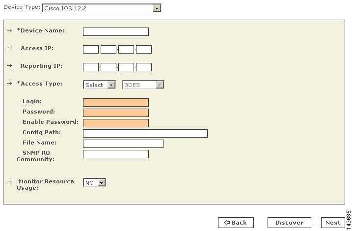
To add a Cisco router running Cisco IOS 12.2 or later, follow these steps:
Step 1
Step 2
Step 3
MARS maps this name to the reporting IP address. This name is used in topology maps, queries, and in the Security and Monitoring Device list. For devices that support the discovery operation, such as routers and firewalls, MARS renames this field's value to match the name discovered in the device configuration, which typically uses the hostname.domain format. For devices that cannot be discovered, such as Windows and Linux hosts and host applications, MARS uses the provided value.
Step 4
To learn more about the access IP address, its role, and dependencies, see Understanding Access IP, Reporting IP, and Interface Settings, page 2-8.
Step 5
To learn more about the reporting IP address, its role, and dependencies, see Understanding Access IP, Reporting IP, and Interface Settings, page 2-8.
Step 6
•
•
•
•
For more information on determining the access type, see Selecting the Access Type, page 2-10.
Step 7
Before you can specify the SNMP RO string, you must define an access IP address. MARS uses the SNMP RO string to read MIBs related to a reporting device's CPU usage, network usage, and device anomaly data and to discover device and network settings.
Step 8
Result: MARS monitors the device for anomalous consumption of resources, such as memory and CPU. If anomalies are detected, MARS generates an incident. Resource utilization statistics are also used to generate reports. For more information, see Configuring Resource Usage Data, page 2-41.
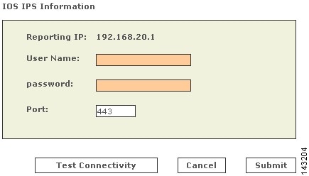
Step 9
Note
Result: The IOS IPS Information page appears.
a.
b.
c.
MARS pulls data using SDEE over HTTPS. The default port number for HTTPS/SDEE is 443. This access allows MARS to retrieve XML files that contain the events generated by the IOS IPS feature.
Result: MARS can query the router for SDEE events.
Step 10
Result: If the username and password are correct and the MARS Appliance is configured as an administrative host for the device, the "Discovery is done." dialog box appears when the discovery operation completes. Otherwise, an error message appears. After the initial pull, the MARS Appliance pulls based on the schedule that you define. For more information, see Scheduling Topology Updates, page 2-39.
Step 11
Result: The submit operation records the changes in the database tables. However, it does not load the changes into working memory of the MARS Appliance. The activate operation loads submitted changes into working memory.
Step 12
Result: MARS begins to sessionize events generated by this device and evaluate those events using the defined inspection and drop rules. Any events published by the device to MARS before activation can be queried using the reporting IP address of the device as a match criterion. For more information on the activate action, see Activate the Reporting and Mitigation Devices, page 2-27.
Cisco Switch Devices
You can manage Cisco switches that run either CatOS or Cisco IOS Software Release 12.2 or later. The configuration of the switch varies between these two operating system, as does the addition of the device in MARS. Adding a Cisco switch involves three steps:
1.
2.
3.
4.
To prepare a Cisco switch running Cisco IOS Software Release 12.2 or later, refer to the following procedures:
•
•
To prepare a Cisco switch running CatOS, refer to the following procedures:
•
•
Adding a Cisco switch running to MARS has two distinct steps. First, you add the base module of the switch, providing administrative access to that device. Second, you add any modules that are running in the switch. For instructions on performing these two steps, refer to the following topics:
•
•
Enable Communications Between Devices Running CatOS and MARS
Before you add a Cisco switch running CatOS to MARS, make sure that you have enabled SNMP, Telnet, SSH, or FTP access to the swtich. First, you must configure the MARS Appliance as an IP address that is permited to access the switch.
For information on permitting IP addresses and specifying the access type, see the following URL:
http://www.cisco.com/en/US/docs/switches/lan/catalyst6500/catos/8.x/configuration/guide/ip_perm.html
Next, you must ensure that your switch is configured to enable the correct access method. The following sections provide guidance on configuring each supported access method:
•
•
•
•
Enable SNMP Administrative Access
To enable configuration discovery using SNMP access to the Cisco switch, refer to your device documentation or the following URL:
IP Access
http://www.cisco.com/en/US/docs/switches/lan/catalyst6500/catos/6.x/configuration/guide/ip_perm.html
Configure SNMP
http://www.cisco.com/en/US/docs/switches/lan/catalyst6500/catos/6.x/configuration/guide/snmp.html
Enable Telnet Administrative Access
To enable configuration discovery using Telnet access to the Cisco switch, refer to your device documentation or the following URL:
IP Access
Enable SSH Administrative Access
To enable configuration discovery using SSH access to the Cisco router or switch, refer to your device documentation or the following URL:
IP Access
Enable FTP-based Administrative Access
To enable configuration discovery using FTP access, you must place a copy the Cisco router's or switch's configuration file on an FTP server to which the MARS Appliance has access. This FTP server must have user authentication enabled.
Note
You must copy the running configuration from the Cisco switch. For information on copying the running configuration, refer to your device documentation or the following URL:
Configure the Device Running CatOS to Generate Required Data
You can configure the following message types:
•
•
•
•
For information on configuring these settings, refer to the following topics:
•
•
Enable SNMP RO Strings on CatOS
If the supervisor SNMP server is not configured, you must perform this procedure.
To configure the supervisor SNMP server and enabled SNMP traps on the Catalyst switch, follow these steps:
Step 1
switch> enableEnter password: <password>switch> (enable)Step 2
switch> (enable) set snmp community read-only <read community>Step 3
switch> (enable) set snmp community read-write <write community>switch> (enable) set snmp community read-write-all <write community>Step 4
switch> (enable) set snmp rmon enableStep 5
switch> (enable) exit
Enable Syslog Messages on CatOS
To configure a Cisco switch running CatOS to send syslog information to MARS, follow these steps:
Step 1
set logging server enableStep 2
set logging server <IP address of MARS Appliance>Step 3
set logging level cdp 7 defaultset logging level mcast 7 defaultset logging level dtp 7 defaultset logging level dvlan 7 defaultset logging level earl 7 defaultset logging level fddi 7 defaultset logging level ip 7 defaultset logging level pruning 7 defaultset logging level snmp 7 defaultset logging level spantree 7 defaultset logging level sys 7 defaultset logging level tac 7 defaultset logging level tcp 7 defaultset logging level telnet 7 defaultset logging level tftp 7 defaultset logging level vtp 7 defaultset logging level vmps 7 defaultset logging level kernel 7 defaultset logging level filesys 7 defaultset logging level drip 7 defaultset logging level pagp 7 defaultset logging level mgmt 7 defaultset logging level mls 7 defaultset logging level protfilt 7 defaultset logging level security 7 defaultset logging server facility SYSLOGset logging server severity 7set logging buffer 250set logging timestamp enable
Enable L2 Discovery Messages
To enable L2 discovery on your Cisco switches, you must enable the spanning tree protocol (STP) and provide the SNMP RO community string. All L 2 devices must support SNMP STP MIB (IETF RFC 1493). The discovered information includes interfaces, Layer 3 (L3) routes, L2 spanning trees, L2 forwarding tables, MAC addresses, and so on.
Note
For more information on configuring STP, see the section, Spanning Tree Protocol at the following URL:
http://www.cisco.com/en/US/products/hw/switches/ps708/prod_configuration_examples_list.html
Add and Configure a Cisco Switch in MARS
MARS monitors Cisco switches running either CatOS or Cisco IOS 12.2.
To add the configuration information that MARS uses to monitor a Cisco switch running Cisco IOS 12.2 or later, follow these steps:
Step 1
Step 2
•
•
Step 3
MARS maps this name to the reporting IP address. This name is used in topology maps, queries, and in the Security and Monitoring Device list. For devices that support the discovery operation, such as routers and firewalls, MARS renames this field's value to match the name discovered in the device configuration, which typically uses the hostname.domain format. For devices that cannot be discovered, such as Windows and Linux hosts and host applications, MARS uses the provided value.
Step 4
To learn more about the access IP address, its role, and dependencies, see Understanding Access IP, Reporting IP, and Interface Settings, page 2-8.
Step 5
To learn more about the reporting IP address, its role, and dependencies, see Understanding Access IP, Reporting IP, and Interface Settings, page 2-8.
Step 6
•
•
•
•
For more information on determining the access type, see Selecting the Access Type, page 2-10.
Step 7
Before you can specify the SNMP RO string, you must define an access IP address. MARS uses the SNMP RO string to read MIBs related to a reporting device's CPU usage, network usage, and device anomaly data and to discover device and network settings.
Step 8
Result: MARS monitors the device for anomalous consumption of resources, such as memory and CPU. If anomalies are detected, MARS generates an incident. Resource utilization statistics are also used to generate reports. For more information, see Configuring Resource Usage Data, page 2-41.
Step 9
Result: If the username and password are correct and the MARS Appliance is configured as an administrative host for the device, the "Discovery is done." dialog box appears when the discovery operation completes. Otherwise, an error message appears. After the initial pull, the MARS Appliance pulls based on the schedule that you define. For more information, see Scheduling Topology Updates, page 2-39.
Step 10
Result: The submit operation records the changes in the database tables. However, it does not load the changes into working memory of the MARS Appliance. The activate operation loads submitted changes into working memory.
Step 11
Result: MARS begins to sessionize events generated by this device and evaluate those events using the defined inspection and drop rules. Any events published by the device to MARS before activation can be queried using the reporting IP address of the device as a match criterion. For more information on the activate action, see Activate the Reporting and Mitigation Devices, page 2-27.
After submitting, you can add modules. See Adding Modules to a Cisco Switch.
Adding Modules to a Cisco Switch
In MARS, you can represent, discover, and monitor modules that are installed in Cisco switches. These modules perform special purpose security functions for the switch, such as firewall or intrusion detection and prevention. MARS recognizes the following switch modules and versions:
•
•
•
•
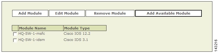
To add a module, you must first add the base module, which is the Cisco switch. After the base module is defined in the web interface, you can discover the modules that are installed in the switch (click Add Available Module) or add them manually (click Add Module).
For instructions on adding and configuring a firewall services module (FWSM), see Cisco Firewall Devices (PIX, ASA, and FWSM), page 4-1.
For instructions on adding and configuring an intrusion detection or prevention services module (IDSM or IPSM), see Cisco IPS Modules, page 6-10.
This section contains the following topics:
•
Add Available Modules
When you perform a discovery operation on a base module, MARS lists the discovered modules. From this list, you can select the modules to monitor using MARS.
To add available modules, follow these steps:
Step 1
If modules are installed in the switch, a list of the modules appears.
Step 2
Step 3
Step 4
Step 5
Basic guidance for editing these settings can be found in the topics that discuss manually adding these modules. See the following topics for more information:
•
•
•
Step 6
Result: The submit operation records the changes in the database tables. However, it does not load the changes into working memory of the MARS Appliance. The activate operation loads submitted changes into working memory.
Step 7
Result: MARS begins to sessionize events generated by this device and the selected modules and evaluate those events using the defined inspection and drop rules. Any events published by the device or its modules to MARS before activation can be queried using the reporting IP address of the device or module as a match criterion. For more information on the activate action, see Activate the Reporting and Mitigation Devices, page 2-27.
Add Cisco IOS 12.2 Modules Manually
To add a module manually, follow these steps:
Step 1
Step 2
Step 3
MARS maps this name to the reporting IP address. This name is used in topology maps, queries, and in the Security and Monitoring Device list. For modules that support the discovery operation, such as router and firewall modules, MARS renames this field's value to match the name discovered in the device configuration, which typically uses the hostname.domain format.
Step 4
To learn more about the access IP address, its role, and dependencies, see Understanding Access IP, Reporting IP, and Interface Settings, page 2-8.
Step 5
To learn more about the reporting IP address, its role, and dependencies, see Understanding Access IP, Reporting IP, and Interface Settings, page 2-8.
Step 6
•
•
•
For more information on determining the access type, see Selecting the Access Type, page 2-10.
Step 7
Before you can specify the SNMP RO string, you must define an access IP address. MARS uses the SNMP RO string to read MIBs related to a reporting device's CPU usage, network usage, and device anomaly data and to discover device and network settings.
Step 8
Result: MARS monitors the module for anomalous consumption of resources, such as memory and CPU. If anomalies are detected, MARS generates an incident. Resource utilization statistics are also used to generate reports. For more information, see Configuring Resource Usage Data, page 2-41.
Step 9
Result: If the username and password are correct and the MARS Appliance is configured as an administrative host for the module, the "Discovery is done." dialog box appears when the discovery operation completes. Otherwise, an error message appears. After the initial pull, the MARS Appliance pulls based on the schedule that you define. For more information, see Scheduling Topology Updates, page 2-39.
Step 10
Result: The submit operation records the changes in the database tables. However, it does not load the changes into working memory of the MARS Appliance. The activate operation loads submitted changes into working memory.
Extreme ExtremeWare 6.x
MARS can use Extreme ExtremeWare switches to enforce L2 mitigation. To configure MARS to communicate with an ExtremeWare switch, you must configure the switch to publish SNMP notifications to the MARS Appliance. In addition, you must add and configure the switch in the web interface.
This section contains the following topics:
•
•
Configure ExtremeWare to Generate the Required Data
To bootstrap an ExtremeWare switch, you must configure two features. First, you must configure the switch to send syslog messages to the MARS Appliance. Next, you must configure the SNMP RO community for MARS to access available L2 information.
To prepare the ExtremeWare device to generate the data required by MARS, follow these steps:
Step 1
configure syslog add <MARS's IP address> local7 debugenable syslogStep 2
enable snmp dot1dTpFdbTableconfigure snmp delete community readonly allconfigure snmp delete community readwrite allconfigure snmp add community readonly encrypted <encrypted community string>configure snmp add community readwrite encrypted <encrypted community string>
Add and Configure an ExtremeWare Switch in MARS
To add and configure an ExtremeWare switch in MARS, follow these steps:
Step 1
Step 2
Step 3
MARS maps this name to the reporting IP address. This name is used in topology maps, queries, and in the Security and Monitoring Device list. For devices that support the discovery operation, such as routers and firewalls, MARS renames this field's value to match the name discovered in the device configuration, which typically uses the hostname.domain format. For devices that cannot be discovered, such as Windows and Linux hosts and host applications, MARS uses the provided value.
Step 4
To learn more about the access IP address, its role, and dependencies, see Understanding Access IP, Reporting IP, and Interface Settings, page 2-8.
Step 5
To learn more about the reporting IP address, its role, and dependencies, see Understanding Access IP, Reporting IP, and Interface Settings, page 2-8.
Step 6
For more information on understanding the access type, see Selecting the Access Type, page 2-10.
Step 7
Before you can specify the SNMP RO string, you must define an access IP address. MARS uses the SNMP RO string to read MIBs related to a reporting device's CPU usage, network usage, and device anomaly data and to discover device and network settings.
Step 8
Result: The submit operation records the changes in the database tables. However, it does not load the changes into working memory of the MARS Appliance. The activate operation loads submitted changes into working memory.
Step 9
Result: MARS begins to sessionize events generated by this device and evaluate those events using the defined inspection and drop rules. Any events published by the device to MARS before activation can be queried using the reporting IP address of the device as a match criterion.
Generic Router Device
You can add any L2 or L3 device to the MARS as long as SNMP is enabled on the device. A generic router refers to any L2 or L3 device that is not listed in the Supported Devices and Software Versions for CS-MARS Local Controller 4.1.
Add and Configure a Generic Router in MARS
To add and configure a generic router device in MARS, follow these steps:
Step 1
Step 2
Step 3
MARS maps this name to the reporting IP address. This name is used in topology maps, queries, and in the Security and Monitoring Device list. For devices that support the discovery operation, such as routers and firewalls, MARS renames this field's value to match the name discovered in the device configuration, which typically uses the hostname.domain format. For devices that cannot be discovered, such as Windows and Linux hosts and host applications, MARS uses the provided value.
Step 4
To learn more about the access IP address, its role, and dependencies, see Understanding Access IP, Reporting IP, and Interface Settings, page 2-8.
Step 5
To learn more about the reporting IP address, its role, and dependencies, see Understanding Access IP, Reporting IP, and Interface Settings, page 2-8.
Step 6
For more information on understanding the access type, see Selecting the Access Type, page 2-10.
Step 7
Before you can specify the SNMP RO string, you must define an access IP address. MARS uses the SNMP RO string to read MIBs related to a reporting device's CPU usage, network usage, and device anomaly data and to discover device and network settings.
Step 8
Result: The submit operation records the changes in the database tables. However, it does not load the changes into working memory of the MARS Appliance. The activate operation loads submitted changes into working memory.
Step 9
Result: MARS begins to sessionize events generated by this device and evaluate those events using the defined inspection and drop rules. Any events published by the device to MARS before activation can be queried using the reporting IP address of the device as a match criterion.