-
User Guide for Cisco Security MARS Local Controller, Release 5.2.x
-
Preface
-
STM Task Flow Overview
-
Reporting and Mitigation Devices Overview
-
Configuring Router and Switch Devices
-
Configuring Firewall Devices
-
Configuring VPN Devices
-
Configuring Network-based IDS and IPS Devices
-
Configuring Host-Based IDS and IPS Devices
-
Configuring Antivirus Devices
-
Configuring Vulnerability Assessment Devices
-
Configuring Generic, Solaris, Linux, and Windows Application Hosts
-
Configuring Database Applications
-
Configuring Web Server Devices
-
Configuring Web Proxy Devices
-
Configuring AAA Devices
-
Configuring Custom Devices
-
Policy Table Lookup on Cisco Security Manager
-
Network Summary
-
Case Management
-
Incident Investigation and Mitigation
-
Queries and Reports
-
Rules
-
Sending Alerts
-
Management Tab Overview
-
System Maintenance
-
Cisco Security MARS XML API Reference
-
Regular Expression Reference
-
Date/Time Format Specfication
-
System Rules and Reports Reference
-
Glossary
-
Index
-
 Feedback
Table Of Contents
Cisco Firewall Devices (PIX, ASA, and FWSM)
Bootstrap the Cisco Firewall Device
Enable Telnet Access on a Cisco Firewall Device
Enable SSH Access on a Cisco Firewall Device
Send Syslog Files From Cisco Firewall Device to MARS
Device-Side Tuning for Cisco Firewall Device Syslogs
List of Cisco Firewall Message Events Processed by MARS
Add and Configure a Cisco Firewall Device in MARS
Add Security Contexts Manually
Edit Discovered Security Contexts
Bootstrap the NetScreen Device
Add the NetScreen Device to MARS
Determine Devices to Monitor and Restrictions
Bootstrap the Check Point Devices
Add the MARS Appliance as a Host in Check Point
Define an OPSEC Application that Represents MARS
Obtain the Server Entity SIC Name
Select the Access Type for LEA and CPMI Traffic
Verify Communication Path Between MARS Appliance and Check Point Devices
Reset the OPSEC Application Certificate of the MARS Appliance
Add and Configure Check Point Devices in MARS
Add a Check Point Primary Management Station to MARS
Manually Add a Child Enforcement Module or Log Server to a Check Point Primary Management Station
Add a Check Point Certificate Server
Edit Discovered Log Servers on a Check Point Primary Management Station
Edit Discovered Firewall on a Check Point Primary Management Station
Define Route Information for Check Point Firewall Modules
Specify Log Info Settings for a Child Enforcement Module or Log Server
Verify Connectivity Between MARS and Check Point Devices
Remove a Firewall or Log Server from a Check Point Primary Management Station
Troubleshooting MARS and Check Point
Configuring Firewall Devices
Revised: May 25, 2007This chapter describes how to bootstrap firewall devices and add them to MARS as reporting devices. Firewall devices come in several form factors: hardware appliances, software applications running on a host, modules that are installed in switches and routers, and modules that install in multifunction security devices.
Multifunction security devices, such as the Cisco Adaptive Security Appliance (ASA), also support non-firewall modules, such as intrusion detection or prevention systems (IDS/IPS). This chapter does not focus on configuring non-firewalling modules. Such discussions are provided in Configuring Network-based IDS and IPS Devices, page 6-1.
This chapter explains how to bootstrap and add the following firewall devices to MARS:
•
Cisco Firewall Devices (PIX, ASA, and FWSM)
Cisco Firewall Devices (PIX, ASA, and FWSM)
MARS support for Cisco firewall devices includes the following:
•
•
•
For the complete list of supported software releases by platform, refer to the latest Supported and Interoperable Devices and Software for Cisco Security MARS Local Controller document.
Because these PIX software is mostly backward compatible, the commands required to bootstrap PIX security appliance remain consistent across the releases. In addition, Cisco ASA and FWSM have much in common with PIX command set.
The taskflow required to configure MARS to monitor a Cisco firewall device is as follows:
1.
For Cisco ASA, PIX 7.0, and FWSM device types, you configure the admin context to accept these sessions.
Note
2.
For Cisco ASA, PIX 7.0, and FWSM device types, you must configure the admin context and each security context.
Note
3.
Note
For Cisco ASA, PIX 7.0, and FWSM, the basic device type represents the admin context. However you must also define or discover each security context and any installed Advanced Inspection and Prevention (AIP) modules running IPS 5.0.
To configure MARS to accept syslog event data and to pull device configurations settings from a Cisco firewall device, you must perform the following tasks:
•
•
Bootstrap the Cisco Firewall Device
You should configure your Cisco firewall devices to act as reporting devices and manual mitigation devices because they perform multiple roles on your network. MARS can benefit from the proper configuration of specific features:
•
•
•
–
–
–
To bootstrap the Cisco firewall device, you must identify the MARS Appliance as an administrative host Enabling administrative access allows MARS to discover the Cisco firewall device configuration settings. To enable administrative access, you must make sure that the MARS Appliance is granted Telnet or SSH administrative access to the firewall device. If you use FTP access type, make sure that you have added its configuration file to an FTP server to allow MARS access to the FTP server.
In addition to configuring specific event types and administrative access, syslog messages should be sent to the MARS Appliance. To prepare the Cisco firewall device to send these messages to the MARS Appliance, you must configure the logging settings associated with each firewall device on your network. To prepare a firewall device to generate the syslog messages and direct them to a specific MARS Appliance, you must:
1.
Before a firewall device can generate syslog messages, you must enable logging for one or more interfaces. In addition, if you configured your firewall device in a failover pair, you can specify the standby firewall device to generate syslog messages as well. You can enable the device to ensure that the standby unit's syslog messages stay synchronized if failover occurs. However, this option results in twice as much traffic on the MARS Appliance.
2.
To generate meaningful reports about the network activity of a firewall device and to monitor the security events associated with that device, you must select the appropriate logging level. The logging level generates the syslog details required to track session-specific data. After you select a logging level, you can define a syslog rule that directs traffic to the MARS Appliance.
3.
•
•
The debug log level generates syslog messages that assist you in debugging. it also generates logs that identify the commands issued during FTP sessions and the URLs requested during HTTP sessions. It includes all emergency, alert, critical, error, warning, notification, and information messages. Alternatively, you can change the severity level of the required messages using the logging message command described in Device-Side Tuning for Cisco Firewall Device Syslogs.
Note
4.
By directing syslog messages generated by a firewall device to MARS, you can process and study the messages.
Tip
To enable administrative connections to the firewall device, select from the following options:
•
•
•
To configure log settings, see Send Syslog Files From Cisco Firewall Device to MARS.
Enable Telnet Access on a Cisco Firewall Device
Step 1
Step 2
telnet <MARS IP address> <netmask of MARS IP address> <interface name>where interface name can be inside, outside, DMZ.
Enable SSH Access on a Cisco Firewall Device
Step 1
Step 2
ssh <MARS IP address> <netmask of the MARS IP address> <interface name>where interface name can be inside, outside, DMZ.
Send Syslog Files From Cisco Firewall Device to MARS
When preparing a Cisco firewall device to publish syslog messages, consider the following restrictions:
•
•
logging host <interface name> <PN-MARS's IP address> format EMBLEMTo send syslog messages to the MARS Appliance, you must enable logging, select the log facility and queue size, and specify the log level to debug.
Step 1
Step 2
•
•
Step 3
logging host <interface name> <MARS IP address>Step 4
logging trap debugging
Tip
The debug messages contain the HTTP URL address information. Therefore, you can create keyword-based rules matching against the firewall message itself. For example, if the debug messages are enabled and users were logging to "http://mail.cisco.com", you could create keyword-based rules that matched against "mail.yahoo.com."
Note
Debug messages are also preferred for troubleshooting. You can define inspection rules that match on on debug-level keywords, which send notifications to the appropriate group. Refer to PIX debug messages for interesting keywords.
Cisco recommends enabling debug for optimal use of your STM solution. If a Cisco firewall device is unable to sustain debug-level messages due to performance reasons, the informational level should be used. In non-debug mode, the URL information is not available; only the 5 tuple is available for queries and reports.
Step 5
logging rate-limit <eps rate desired> 1Step 6
Step 7
Device-Side Tuning for Cisco Firewall Device Syslogs
The default level for many of the events that are studied by MARS is the debug level, which can generate a high volume of additional events that are not used by MARS. If you are experiencing an influx of these other events, you can use the logging message command to either turn off events or change the severity level of the event to a level that generates required messages but not as many as debug.
This topic identifies the commands to use to change the log level from the command line, as well as identifies those messages consumed by MARS and their default severity level.
Logging Message Command
The following references provide details for using the logging message command on the appropriate firewall device:
Cisco ASA and Cisco PIX
•
http://www.cisco.com/en/US/docs/security/asa/asa72/configuration/guide/monitor.html#wp1065731
•
http://www.cisco.com/en/US/docs/security/asa/asa72/configuration/guide/monitor.html#wp1065706
•
http://www.cisco.com/en/US/docs/security/asa/asa72/command/reference/l2_72.html#wp1689570
•
http://www.cisco.com/en/US/docs/security/asa/asa72/system/message/logmsgs.html
Cisco FWSM
•
http://www.cisco.com/en/US/docs/security/fwsm/fwsm32/configuration/guide/monitr_f.html#wp1099894
•
http://www.cisco.com/en/US/docs/security/fwsm/fwsm31/configuration/guide/monitr_f.html#wp1099869
•
http://www.cisco.com/en/US/docs/security/fwsm/fwsm31/command/reference/l2.html#wp1565791
•
http://www.cisco.com/en/US/docs/security/fwsm/fwsm31/system/message/fwsm_log.html
List of Cisco Firewall Message Events Processed by MARS
The following list of events are processed by MARS. By changing the severity level for these events to ensure they are within the logging level you have selected, you can typically reduce the load on your firewall logging by 5-15%. However, the primary consumer of resources will remain the session detail events, which are processed and analyzed by MARS.
Starting with MARS version, the system can correctly parse syslogs at customized logging levels. Therefore, you can move the syslogs processed by MARS to a lower level and then set the log to that level, for example logging level 6. Use the command logging message message-id level level on the ASA, or PIX, to move a syslog message to a new level.
The following syslog message IDs are those required for proper sessionization. If you change the logging level of the firewall, ensure that the following messages IDs are generated at the new level so the MARS Appliance receives them.
Note
•
•
•
•
•
•
•
•
•
•
•
•
•
•
•
•
•
•
•
•
•
•
•
•
•
•
•
•
•
•
•
•
•
•
•
•
Add and Configure a Cisco Firewall Device in MARS
The process of adding a PIX security appliance, Cisco ASA, or FWSM to MARS involves many of the same steps, regardless of the version of software that is running. The process is exactly the same for PIX software versions 6.0, 6.1, 6.2, and 6.3. However, Cisco ASA, PIX 7.0, and FWSM provide the ability to define multiple security contexts, or virtual firewalls.
Adding a Cisco ASA, PIX 7.0, and FWSM to MARS has two distinct steps. First, you must define the settings for the admin context. Then, if multiple context mode is enabled, you define or discover the settings for its security contexts. These Cisco firewall device have two type of contexts: one admin context, which is used for configuration of the device itself, and one or more security contexts. For Cisco ASA, you can also define or discover any modules that are installed in the appliance.
To be monitored by MARS, the Cisco ASA, PIX 7.0, and FWSM device types have the following additional requirements:
•
•
Note
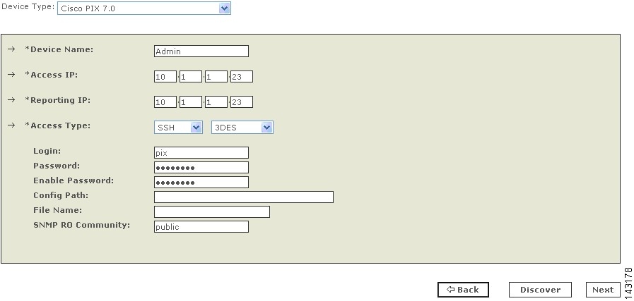
To add and configure a Cisco firewall device, follow these steps:
Step 1
•
•
Step 2
•
•
•
•
•
•
•
•
•
•
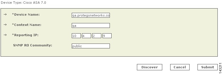
Step 3
MARS maps this name to the reporting IP address. This name is used in topology maps, queries, and in the Security and Monitoring Device list. For devices that support the discovery operation, such as routers and firewalls, MARS renames this field's value to match the name discovered in the device configuration, which typically uses the hostname.domain format. For devices that cannot be discovered, such as Windows and Linux hosts and host applications, MARS uses the provided value.
Step 4
Note
To learn more about the access IP address, its role, and dependencies, see Understanding Access IP, Reporting IP, and Interface Settings, page 2-8.
Step 5
Note
To learn more about the reporting IP address, its role, and dependencies, see Understanding Access IP, Reporting IP, and Interface Settings, page 2-8.
Step 6
•
•
•
Note
For more information on determining the access type, see Selecting the Access Type, page 2-10.
Step 7
Before you can specify the SNMP RO string, you must define an access IP address. MARS uses the SNMP RO string to read MIBs related to a reporting device's CPU usage, network usage, and device anomaly data and to discover device and network settings.
Step 8
Result: MARS monitors the device for anomalous consumption of resources, such as memory and CPU. If anomalies are detected, MARS generates an incident. Resource utilization statistics are also used to generate reports. For more information, see Configuring Resource Usage Data, page 2-41.
Step 9
•
•
For PIX and FWSM, you can add one or more security contexts. For Cisco ASA, you can add one or more security contexts or Advanced Inspection and Prevention (AIP) modules, running the Cisco IPS 5.x software.
Step 10
Result: If the username and password are correct and the MARS Appliance is configured as an administrative host for the device, the "Discovery is done." dialog box appears when the discovery operation completes. Otherwise, an error message appears. After the initial pull, the MARS Appliance pulls based on the schedule that you define. For more information, see Scheduling Topology Updates, page 2-39.
Step 11
Result: The submit operation records the changes in the database tables. However, it does not load the changes into working memory of the MARS Appliance. The activate operation loads submitted changes into working memory.
Step 12
Result: MARS begins to sessionize events generated by this device and evaluate those events using the defined inspection and drop rules. Any events published by the device to MARS before activation can be queried using the reporting IP address of the device as a match criterion. For more information on the activate action, see Activate the Reporting and Mitigation Devices, page 2-27.
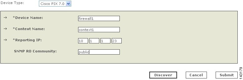
Add Security Contexts Manually
You can manually define security contexts in PIX 7.0, Cisco ASA, or FWSM.
Step 1
•
•
Step 2
•
•
•
Step 3
MARS maps this name to the reporting IP address. This name is used in topology maps, queries, and in the Security and Monitoring Device list. For devices that support the discovery operation, such as routers and firewalls, MARS renames this field's value to match the name discovered in the device configuration, which typically uses the hostname.domain format. For devices that cannot be discovered, such as Windows and Linux hosts and host applications, MARS uses the provided value.
Step 4
This name must exactly match the context name defined on the device.
Step 5
To learn more about the reporting IP address, its role, and dependencies, see Understanding Access IP, Reporting IP, and Interface Settings, page 2-8.
Step 6
Before you can specify the SNMP RO string, you must define an access IP address. MARS uses the SNMP RO string to read MIBs related to a security context's CPU usage, network usage, and device anomaly data and to discover device and network settings.
Step 7
This discovery collects all of the route, NAT, and ACL-related information. In addition, the name of the device may change to the hostname.domain format if it was not already entered as such.
Step 8
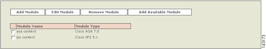
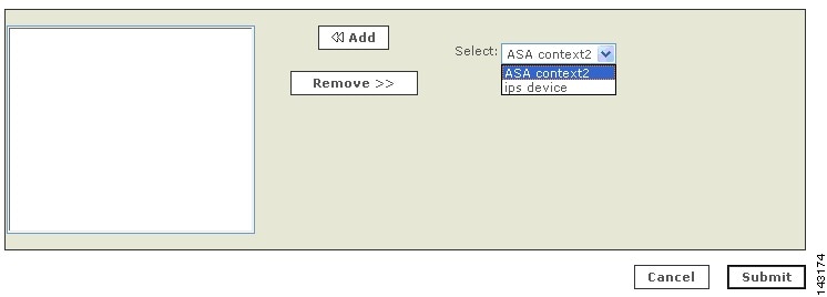
Add Discovered Contexts
When you select Discover on a Cisco ASA, PIX 7.0 or FWSM, MARS discovers the contexts that are defined for that firewall device. However, you must still manually add discovered contents.
Note
Step 1
•
•
Step 2
Step 3
Step 4
Step 5
After you add discovered contexts, you must edit them to provide the contact information required by MARS. Continue with Edit Discovered Security Contexts.
Edit Discovered Security Contexts
Note
Step 1
•
•
Step 2
Step 3
Before you can specify the SNMP RO string, you must define an access IP address. MARS uses the SNMP RO string to read MIBs related to a reporting device's CPU usage, network usage, and device anomaly data and to discover device and network settings.
Step 4
Result: MARS monitors the device for anomalous consumption of resources, such as memory and CPU. If anomalies are detected, MARS generates an incident. Resource utilization statistics are also used to generate reports. For more information, see Configuring Resource Usage Data, page 2-41.
Step 5
Step 6
NetScreen ScreenOS Devices
MARS can monitor NetScreen ScreenOS devices, versions 4.0 and 5.0. To enable this monitoring, you must:
1.
2.
3.
4.
To accomplish these requirements, you must perform two procedures:
•
•
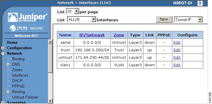
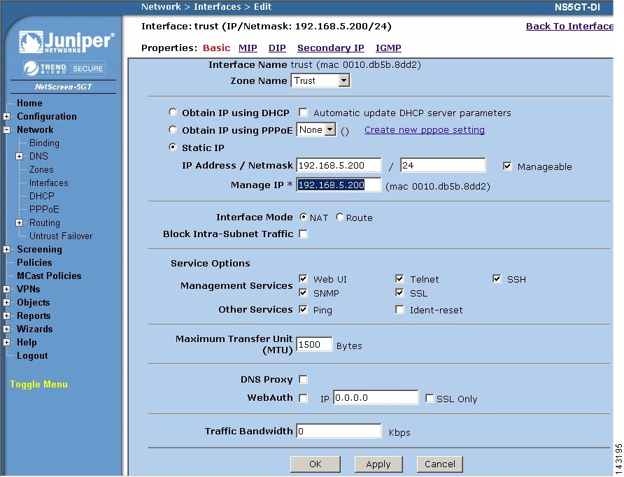
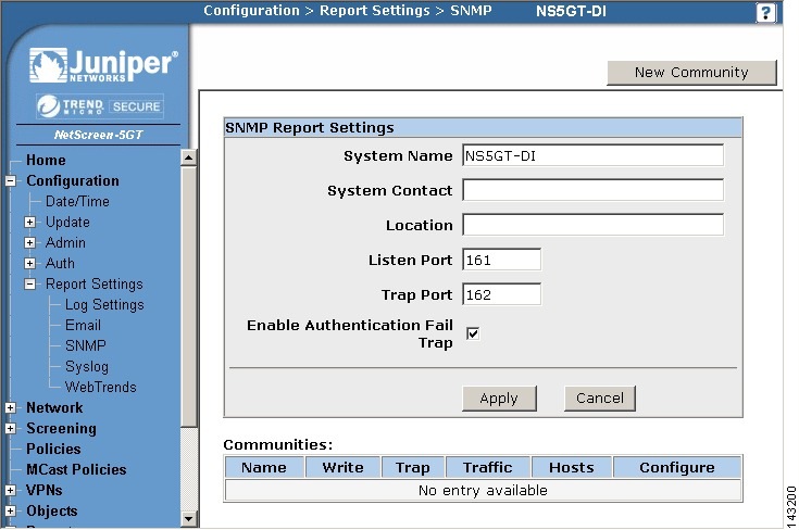
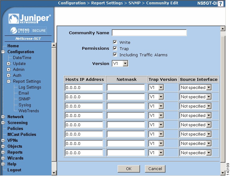
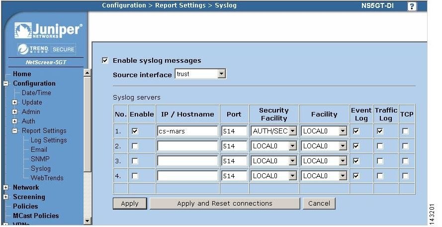
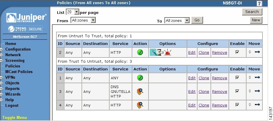
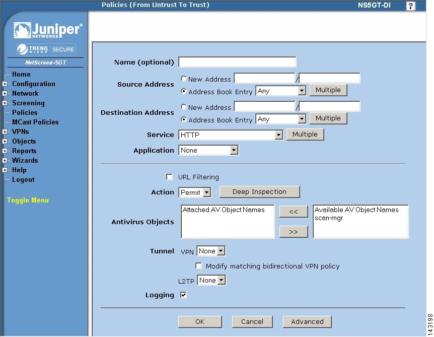
Bootstrap the NetScreen Device
To prepare the NetScreen device to be monitored by MARS, follow these steps:
Step 1
Step 2
Step 3
Step 4
•
•
•
•
MARS can only use one of the access methods to perform configuration discovery. This value will also be selected in the Access Type value of Add the NetScreen Device to MARS.
Step 5
Step 6
Step 7
Step 8
Step 9
Step 10
Step 11
Step 12
Step 13
Step 14
Step 15
Step 16
Step 17
Step 18
Step 19
Add the NetScreen Device to MARS
Step 1
Step 2
Step 3
MARS maps this name to the reporting IP address. This name is used in topology maps, queries, and in the Security and Monitoring Device list. For devices that support the discovery operation, such as routers and firewalls, MARS renames this field's value to match the name discovered in the device configuration, which typically uses the hostname.domain format. For devices that cannot be discovered, such as Windows and Linux hosts and host applications, MARS uses the provided value.
Step 4
To learn more about the access IP address, its role, and dependencies, see Understanding Access IP, Reporting IP, and Interface Settings, page 2-8.
Step 5
To learn more about the reporting IP address, its role, and dependencies, see Understanding Access IP, Reporting IP, and Interface Settings, page 2-8.
Step 6
•
•
•
For more information on determining the access type, see Selecting the Access Type, page 2-10.
Step 7
Before you can specify the SNMP RO string, you must define an access IP address. MARS uses the SNMP RO string to read MIBs related to a reporting device's CPU usage, network usage, and device anomaly data and to discover device and network settings.
Step 8
Result: If the username and password are correct and the MARS Appliance is configured as an administrative host for the device, the "Discovery is done." dialog box appears when the discovery operation completes. Otherwise, an error message appears. After the initial pull, the MARS Appliance pulls based on the schedule that you define. For more information, see Scheduling Topology Updates, page 2-39.
Step 9
Result: The submit operation records the changes in the database tables. However, it does not load the changes into working memory of the MARS Appliance. The activate operation loads submitted changes into working memory.
Step 10
Result: MARS begins to sessionize events generated by this device and evaluate those events using the defined inspection and drop rules. Any events published by the device to MARS before activation can be queried using the reporting IP address of the device as a match criterion. For more information on the activate action, see Activate the Reporting and Mitigation Devices, page 2-27.
Check Point Devices
The Check Point security product family can be distributed and tiered. As such, you must understand the deployment method, components, and release versions of this product family, their relationships, and how MARS interacts with them. You must also understand the many acronyms and abbreviations associated with this product family. Table 4-1 lists the abbreviations and acronyms used in the topics that follow.
To understand what MARS supports, we must first clarify the product terminology used by Check Point. NG refers to the 5.x product family, and it included three feature packs: FP1, FP2, and FP3. NG is different from NG AI in that NG AI improved upon, and renamed, the SmartDefense feature set that was introduced in NG FP2. NG AI also provides a larger number of application-aware inspections,; hence the name Application Intelligence. NG AI included releases R54 and R55. NGX refers to the 6.x product family and began with the R60 release.
MARS supports and has been tested with the following releases:
•
•
•
The different security platforms, Provider-1, SiteManager-1, SmartCenter, and SmartCenter Pro are bundles of the technologies released under the NG, NG AI, and NGX release trains. From this perspective, MARS works with any of the security platforms as long as it belongs to one of the supported release trains.
Check Point Provider-1 is a security management system for the managed security service providers (MSSP) and multi-site enterprises, respectively. Service providers are able to manage the Check Point gateways (firewall and VPN gateways) on their customer sites. The security policies and the system configurations are stored on the MDS. Each per-customer security policy is managed through a CMA, which also reside on the MDS. The Provider-1 system allows the service provider and the end customers to maintains separate log servers, using the MLM and CLM respectively. The user interface for Provider-1 is called the MDG. This system also support a tiered fault-tolerant configuration via redundancy at the gateway, CMA, or MDS level.
The Provider-1 system ensures secure and private communication between its components and Check Point gateways. Each CMA has its own internal certificate authority that issues certificates for secure communication between the CMA, log servers, and its own network. All communication between MDSs is authenticated and secured, and every MDS communicates securely with the CMAs that it houses.
The SiteManager-1 system operates much the same as Provider-1; however, it is targeted toward large enterprise customers. The Check Point components are the same as those found in Provider-1.
SmartCenter and SmartCenter Pro are security management systems also targeted toward enterprise customers. They can support the Provider-1 system, serving as a backup server at the CMA level. However, their primary function is to provide centralized security and VPN policy and security event management through SmartDashboard, which is the user interface for both systems. From the MARS perspective, SmartCenter has the ability to extend the view of the network by managing the policies and events associated with gateway and desktop nodes:
•
•
•
•
MARS monitors the primary management servers, such as the MDS in Provider-1 and SiteManager-1 and the SmartCenter Server in SmartCenter and SmartCenter Pro. These management servers are where the actual security and audit policies are centrally managed and stored. If the Check Point deployment requires, MARS also monitors those components managed by the management stations, such as individual firewalls, VPN gateways, and log servers. Whether you configure MARS to monitor these remote components depends on whether their security event logs are propagated to the centralized management servers (SmartCenter or CMA). If the logs are not forwarded to the primary management server, then you must define where the log repository exists, whether local to the enforcement module, or forwarded to a separate logging module (CLM).
In addition to understanding the components, it is important to understand how Check Point components use Secure Internal Communications (SIC) to securely communicate with each other and with third-party OPSEC applications. SIC is the process by which MARS Appliance authenticates to the SmartCenter Server and other Check Point components. SIC uses a shared secret as the seed for negotiating session keys. This shared secret is referred to as an activation key. The authentication and communication setup works as follows:
1.
2.
3.
The following topics support the integration of MARS into a Check Point environment:
•
•
•
•
Determine Devices to Monitor and Restrictions
To configure Check Point devices, you must identify the central management server and managed components, bootstrap them, and add and configure them in the MARS web interface. The Check Point product line and release, as well as the number of devices managed, determines which tasks you must perform to configure MARS to monitor your Check Point devices.
Representing a Check Point device in MARS involve two steps:
1.
2.
When managing SmartCenter and SmartCenter Pro, the primary management station is the SmartCenter server. When managing Provider-1/SiteManager-1 releases NG FP3, NG AI (R55), and NGX (R60), the primary management station is not the MDS, but each CMA defined under the MDS. In other words, you must define each CMA as a separate primary management station. The child enforcement modules are those gateways and logs servers (CLMs) managed as part of that customer or site as defined by the CMA.
Part of what you must determine is where the security event logs are stored. Two options exist:
•
•
If the security events are stored in a distributed fashion, you must plan to define and establish SIC communication between the MARS Appliance and each Check Point log module. For SmartCenter and SmartCenter Pro, the server SIC DN is the one assigned to the primary management station. However, for Provider-1 and SiteManager-1, the server SIC DN varies based on release. For Provider-1 and SiteManager-1 NG FP3 and NG AI (R55), the server SIC DN is the one associated with the CMA. For Provider-1 and SiteManager-1 NGX (R60), you can use the SIC assigned to the MDS for all CMAs and CLMs that you define.
One other restriction exists with the Provider-1 and SiteManager-1 products. For Provider-1 and SiteManager-1 NG FP3 and NG AI (R55), you must define an OPSEC application representing the MARS Appliance in each CMA (using the CMAs SmartDashboard user interface). For Provider-1 and SiteManager-1 NGX (R60), you can define one OPSEC application representing the MARS Appliance and push that definition to all CMAs and CLMs managed by the MDS.
Bootstrap the Check Point Devices
Bootstrapping the Check Point devices involves preparing those devices to send data to the MARS Appliance, as well as enabling the MARS Appliance to discover the Check Point configuration settings. In addition to preparing the Check Point devices, you must gather the information required to represent the Check Point devices in the MARS web interface.
You bootstrap the central Check Point management server, whether it be a CMA or a SmartCenter server by defining the MARS Appliance as a target log host and OPSEC Application object.
1.
2.
3.
4.
5.
6.
To perform this task, you need a Check Point user account with administrative privileges. This account must be able to create a new host, define OPSEC application, define and install new policies, and access the settings of each managed Check Point component.
After completing this task, you should have collected the following information:
•
•
•
To bootstrap the Check Point devices, perform the following procedures:
•
•
•
•
•
Add the MARS Appliance as a Host in Check Point
Representing the MARS Appliance in Check Point enables the following supporting tasks:
•
•
•
To define the MARS Appliance as a host, follow these steps:
Step 1
If you are using SmartCenter, use the SmartDashboard for that server. If you are using Provider-1 or SiteManager-1 NG FP3 or NG AI (R55), use the SmartDashboard of the CMA. If you are using Provider-1 or SiteManager-1 NGX, use the MDG.
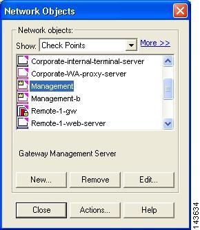
Step 2
Result: The Network Objects dialog box appears.
Step 3
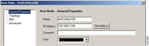
Result: The Host Node dialog appears, with the General Properties settings selected.
Step 4
Any Check Point policies defined to enable access or send logs to this appliance will reference the appliance by this name. Cisco best practice recommends using the actual hostname of the MARS Appliance.
Step 5
Typically, the monitoring interface is eth0. However, if one or more intermediate gateways are applying NAT rules to the physical IP address, enter the IP address that is exposed to the Check Point central management server.
Step 6
Step 7
Result: The host representing the MARS Appliance is defined. You can now use this host when defining new policies in the Check Point user interface.
Step 8
Define an OPSEC Application that Represents MARS
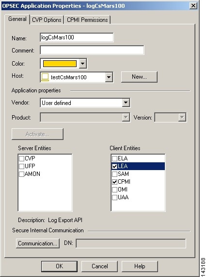
To integrate a third-party OPSEC application with Check Point components, you must define the application and associate it with the host on which the application is running. In addition to identifying this OPSEC application to the Check Point system, this procedure results in the generation of the client SIC DN for the MARS Appliance. Both the client SIC DN and the server SIC DN, obtained in Obtain the Server Entity SIC Name, are required to enable secure communications between the appliance and Check Point components.
This procedure also involves selecting an activation key, or shared secret, that is also required to enable the secure communications. You must record both the activation key and the client SIC DN for use when defining the Check Point devices in the MARS web interface.
Step 1
If you are using SmartCenter, use the SmartDashboard for that server. If you are using Provider-1 or SiteManager-1 NG FP3 or NG AI (R55), use the SmartDashboard of the CMA. If you are using Provider-1 or SiteManager-1 NGX, use the MDG.
Step 2
Result: The Servers and OPSEC Application dialog box appears.
Step 3
Result: The OPSEC Application Properties dialog box appears.
Step 4
This value must be different from the name specified in Step 4 of Add the MARS Appliance as a Host in Check Point. Best practice recommends using the actual hostname of the host object plus some other descriptor, which combines for a unique name.
Step 5
Step 6
Step 7
Step 8
These values identify the OPSEC services required by the MARS Appliance.
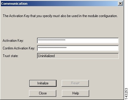
Step 9
Result: The Communication dialog box appears.
Step 10
Note
Step 11
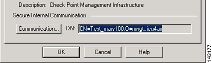
Result: The client SIC DN is generated and the Communication dialog box closes, returning to the OPSEC Application Properties dialog box. The new SIC appears in the DN field.
Step 12
Step 13
This value is used to populate the Client Entity SIC Name field of MARS in Add a Check Point Primary Management Station to MARS.
Tip
Step 14
Step 15
Step 16
Result: The OPSEC Application that represents MARS is defined and associated to the correct host. You also have obtained the activation key and client SIC DN for later use in Add a Check Point Primary Management Station to MARS.
Step 17
Result: This operation updates the remote Check Point components (child enforcement modules), such as CMAs, CLMs, log servers, and firewalls. It provides them with the authorization and credentials of the MARS Appliance, as an OPSEC component and SIC client.
Tip
Step 18
Obtain the Server Entity SIC Name
The server SIC DN is one of the shared secrets used to provide non-repudiation during a secure communication between a Check Point component and the MARS Appliance. This value is used when defining a primary management station in MARS as defined in Add a Check Point Primary Management Station to MARS.
Step 1
If you are using SmartCenter, use the SmartDashboard for that server. If you are using Provider-1 or SiteManager-1 NG FP3 or NG AI (R55), use the SmartDashboard of the CMA. If you are using Provider-1 or SiteManager-1 NGX (R60), use the MDG.
Step 2
Step 3
Step 4
Which Check Point component you select depends on which SIC you need and what Check Point system you are using. Specifically, you want to obtain SICs for:
•
•
•
Management servers are the following devices:
•
•
•
Log servers are the following devices:
•
•
•
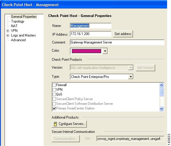
Step 5
The Check Point Host - Management dialog box appears, with the General Properties page selected.
Step 6
This value is used to populate the Server Entity SIC Name field of MARS in either Add a Check Point Primary Management Station to MARS, Manually Add a Child Enforcement Module or Log Server to a Check Point Primary Management Station, or Edit Discovered Firewall on a Check Point Primary Management Station.
Step 7
Step 8
Step 9
Step 10
Select the Access Type for LEA and CPMI Traffic
Check Point devices use special access types for configuration discovery and event log queries. For configuration discovery, the protocol is CPMI. For event log queries, the protocol is LEA. Each of these protocols has specific configurable attributes, including whether to use bulk encryption, what cipher to use, and what port to use for communications.
You must understand what the supported settings are so that you can verify the Check Point devices are configured correctly. MARS supports only three of the available Check Point authentication mode:
•
•
•
These access protocols are configured as follows:
Note
•
This line is required in the fwopsec.conf file. The service value is either LEA_SERVEAR or CPMI_SERVER. Two possible values exist for port_number: 0, which indicates an the server is not listening for authenticated session requests, and the port number of an authenticated and/or encrypted protocol. If the port_number value is 0, you must configure the server to listen for session requests in CLEAR mode on a valid port using the <service> port <port_number> settings.
•
The service value is either LEA_SERVER or CPMI_SERVER. Two possible values are supported for cipher: sslca for authentication and encryption using a symmetric key cipher, or asym_sslca for authentication and encryption using an asymmetric key cipher. If the auth_port setting is set to 0 (zero) for this service, then you do not need to specify the auth_type in the fwopsec.conf file. You can comment out this line.
•
This line is required in the fwopsec.conf file. The service value is either LEA_SERVER or CPMI_SERVER. The value for port_number must match the port number on which the desired network service listens. A port_number of 0 (zero) indicates that log server is not listening in CLEAR mode.
If it is some other number, then any service can come pull the logs without authenticating. For LEA_SERVER, you cannot use port 18184, as it is used for encrypted log communications. For CPMI_SERVER, you cannot use port 18190. When CLEAR is enabled, authentication is disabled for this port. Any host with access to the Check Point component at this port can pull logs. If you chose to enable CLEAR, which is less expensive in terms of overall transaction costs, you define policies that restrict access to the MARS Appliance and other know management hosts.
Note
The following example indicates that LEA is using ASYMSSLCA-based authentication connecting over port 18184 (default), the traffic is encrypted via SSL, and the log server is not listening for requests in cleartext.
LEA_SERVER auth_port 18184LEA_SERVER auth_type asym_sslcaLEA_SERVER port 0The following example indicates that the log server is listening for requests in cleartext at port 18187. Such requests will be serviced and the sessions will be neither authenticated nor encrypted.
LEA_SERVER port 18187Check Point uses the following default settings:
•
•
To review or change the access type settings, follow these steps:
Step 1
For Provider-1 and SiteManager-1, this server is the MDS, MLM, or CLM. Otherwise, it is the SmartCenter server.
Step 2
The following example uses the find command to locate the file. Customer1 identifies the CLM.
[Expert@logger]# find . -name "fwopsec.conf" -print./var/opt/CPfw1-R55/conf/fwopsec.conf./var/opt/CPmds-R55/customers/Cust1Log/CPfw1-R55/conf/fwopsec.conf[Expert@logger]# cd /var/opt/CPmds-R55/customers/Cust1Log/CPfw1-R55/confStep 3
Step 4
Step 5
Step 6
Result: The CPMI and LEA servers are restarted, which reloads their configuration information, and ensures they are listening to the correct ports for session requests.
Step 7
Create and Install Policies
You must create firewall policies that permit the MARS Appliance to access the relevant ports of the Check Point central management server and any remote log servers. The default ports are as follows:
•
•
•
However, you must use the CPMI and LEA servers settings specified in Select the Access Type for LEA and CPMI Traffic. When the policies are defined, you must install them on any firewall modules that inspect traffic between the Check Point components and the MARS Appliance.
If the management server has a Check Point firewall installed, follow these steps:
Step 1
If you are using SmartCenter, use the SmartDashboard for that server. If you are using Provider-1 or SiteManager-1 NG FP3 or NG AI (R55), use the SmartDashboard of the CMA. If you are using Provider-1 or SiteManager-1 NGX, use the MDG.
Step 2
If you have enabled CPMI discovery, the service condition must include CMPI. To enable the log access, the service list must include FW1_lea.
Step 3
The Track column of each rule should display the Log action. To enable logging, right-click the Track field of a rule and select Log on the shortcut menu.
Step 4
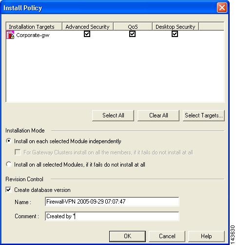
Step 5
The target devices should be those firewalls that reside between the Check Point components and the MARS Appliance.
Step 6
Result: The security policies on the target firewall devices are updated, enabling CPMI and LEA traffic flows between the Check Point components and the MARS Appliance.
Tip
Verify Communication Path Between MARS Appliance and Check Point Devices
You should verify that the MARS Appliance can reach the Check Point devices, including the SmartCenter server and the remote log servers. Use the telnet command at CLI of the MARS Appliance to verify access to the SmartCenter server and log servers. The ports to check are defined in Select the Access Type for LEA and CPMI Traffic. For more information on accessing the CLI, see Log In to the Appliance via the Console, page 6-2 of the Install and Setup Guide for Cisco Security Monitoring, Analysis, and Response System.
The command syntax is as follows
telnet <ip_address> <port_number>
If you are unsuccessful, verify the settings of the ports for each Check Point component and verify that no firewalls are blocking the traffic. For more information on telnet, see telnet, page A-56 in the Install and Setup Guide for Cisco Security Monitoring, Analysis, and Response System.
Reset the OPSEC Application Certificate of the MARS Appliance
If you encounter an error when pulling the certificate as part of defining the Check Point devices in the MARS web interface, you must reset the certificate before you can attempt to pull it again. This procedure details how to reset the certificate, or SIC, associated with the OPSEC Application that is associated with the host that represents the MARS Appliance.
To reset the OPSEC application certificate, follow these steps:
Step 1
If you are using SmartCenter, use the SmartDashboard for that server. If you are using Provider-1 or SiteManager-1 NG FP3 or NG AI (R55), use the SmartDashboard of the CMA. If you are using Provider-1 or SiteManager-1 NGX, use the MDG.
Step 2
Result: The Servers and OPSEC Application dialog box appears.
Step 3
Step 4
Result: The OPSEC Application Properties dialog box appears.
Step 5
Result: The Communication dialog box appears.
Step 6
Step 7
Result: The client SIC DN is generated and the Communication dialog box closes, returning to the OPSEC Application Properties dialog box. The new SIC appears in the DN field.
Step 8
Step 9
Result: The OPSEC Application that represents MARS is defined and associated to the correct host. You also have obtained the activation key and client SIC DN for later use in Add a Check Point Primary Management Station to MARS.
Add and Configure Check Point Devices in MARS
After you identify and bootstrap the Check Point reporting devices and install the policies that enable the required traffic flows, you must represent those devices in MARS, which uses this information to communicate with the devices. When adding a Check Point device, you add two types of devices:
•
•
With these definitions in mind, adding and configuring the Check Point device involves the following:
1.
2.
3.
4.
5.
6.
7.
8.
9.
10.
11.
12.
13.
To add a Check Point device in MARS, you must perform the following procedures:
•
•
•
•
•
If discovery of Check Point configuration settings is not enabled for MARS, you must perform the following manual configuration procedures:
•
•
Before You Begin
To perform this procedure, you need the following information:
•
•
•
•
Add a Check Point Primary Management Station to MARS
The primary management station represents one of the following:
•
•
Note
You must define each individual CMA of a Provider-1 or SiteManager installation, regardless of the release and version.
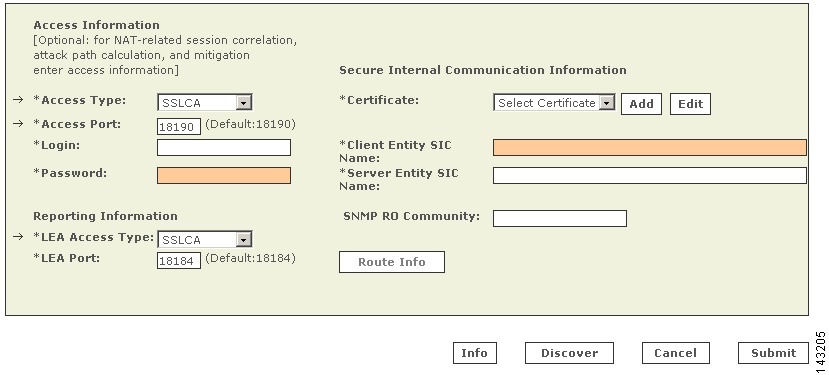
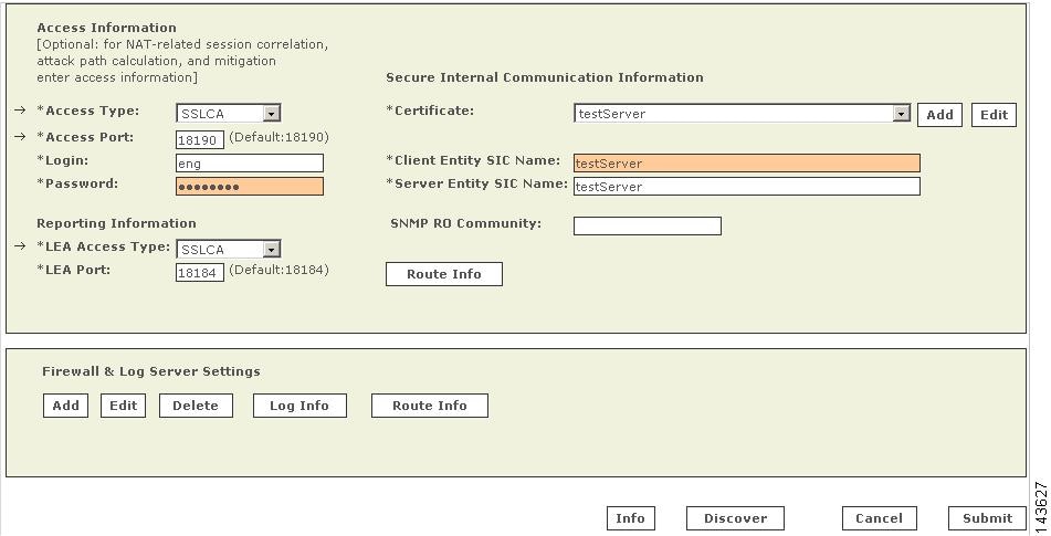
Step 1
Step 2
•
•
Step 3
•
•
•
This address represents either a virtual IP address associated with a CMA or the physical IP address of the SmartCenter server. To learn more about the reporting IP address, its role, and dependencies, see Understanding Access IP, Reporting IP, and Interface Settings, page 2-8.
Step 4
This address represents either a virtual IP address associated with a CMA or the physical IP address of the SmartCenter server. To learn more about the interface settings, its role, and dependencies, see Understanding Access IP, Reporting IP, and Interface Settings, page 2-8.
Step 5
Result: MARS monitors the device for anomalous consumption of resources, such as memory and CPU. If anomalies are detected, MARS generates an incident. Resource utilization statistics are also used to generate reports. For more information, see Configuring Resource Usage Data, page 2-41.
Step 6
Step 7
Step 8
The following options are available:
•
•
Step 9
•
•
•
•
Step 10
•
•
Step 11
•
•
•
Step 12
Before you can specify the SNMP RO string, you must define an access IP address on host that represents the primary management station and you must configure the Access Information settings on the primary management station. MARS uses the SNMP RO string to perform resource utilization monitoring. Currently, it is not used for configuration or log discovery.
Step 13
Before you can enable this feature, you must provide a SNMP RO Community string.
Result: MARS monitors the device for anomalous consumption of resources, such as memory and CPU. If anomalies are detected, MARS generates an incident. Resource utilization statistics are also used to generate reports. For more information, see Configuring Resource Usage Data, page 2-41.
Step 14
Step 15
Result: If the username and password are correct and the MARS Appliance is configured as an administrative host for the device, the "Discovery is done." dialog box appears when the discovery operation completes. Otherwise, an error message appears. After the initial pull, the MARS Appliance pulls based on the schedule that you define. For more information, see Scheduling Topology Updates, page 2-39.
Note
Step 16
Result: The submit operation records the changes in the database tables. However, it does not load the changes into working memory of the MARS Appliance. The activate operation loads submitted changes into working memory.
Step 17
•
•
Step 18
Result: Once the MARS Appliance is activated, it connects to the Check Point log modules and retrieves the traffic and audit logs. MARS also begins to sessionize events generated by this device and evaluate those events using the defined inspection and drop rules. Any events published by the device to MARS before activation can be queried using the reporting IP address of the device as a match criterion. For more information on the activate action, see Activate the Reporting and Mitigation Devices, page 2-27.
Manually Add a Child Enforcement Module or Log Server to a Check Point Primary Management Station
If you have not enabled configuration discovery on the primary management station or if one or more of the managed firewalls uses a log server that is not managed by the primary management station, you can manually define firewalls or log servers. Your goal should be to represent all of the firewalls managed by this primary management station and all log servers used by those firewalls and the primary management station. While MARS does not discover configuration settings of the firewalls, it uses the defined information to discover topology, calculate attack paths, and identify preferred mitigation points in the network.
For example, if you are defining a primary management station that represents a CMA, you must define the CLM associated with that CMA. Any firewalls managed under that CMA may either act as their own log servers, publish information to the CLM, or publish information to a MLM. In the case of the later, you must define that relationship by defining the firewalls and then specifying which log servers pull their traffic and audit logs. First, however, must also define the MLM settings, as it is a log server that external to the perspective of the CMA, and it cannot be referred by a firewall until it has been defined. The CLM, however, would be considered part of the CMA (assuming the reporting IP and LEA settings are specified), so you would not define a separate child enforcement module to represent it. Instead, you would select the Management option in the Log Info dialog for firewalls that use the CLM as their log server. For more information on selecting the log server option, see Specify Log Info Settings for a Child Enforcement Module or Log Server.
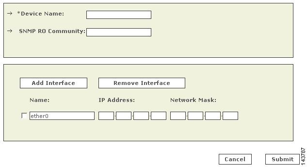
To manually define a child enforcement module that is managed by the primary management station or a log server to which either the primary management station or a child enforcement module publishes its audit and security logs, follow these steps:
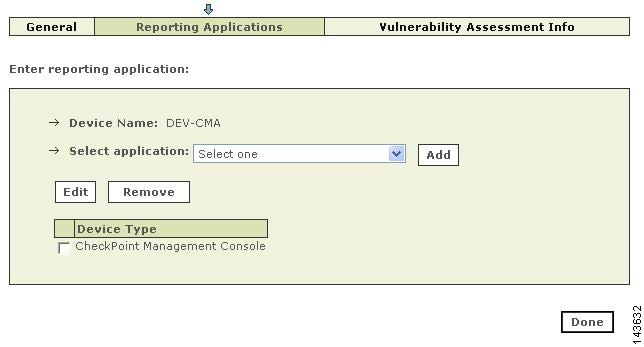
Step 1
Step 2
Such devices have CheckPoint Management Console as an entry in the Device Type column.
Step 3
Step 4
The Access Information page appears.
Step 5
Result: The list of available hosts appears.
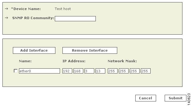
Step 6
•
Result: A page with a read-only device name appears, prompting you to specify the SNMP RO Community string.
•
Result: A page appears, prompting you to specify device name and SNMP RO Community string.
Step 7
MARS maps this name to the IP address specified in the interfaces. This name is used in topology maps, queries, and appears in the Children column of the base Check Point module in the Security and Monitoring Device list.
Step 8
Before you can specify the SNMP RO string, you must define an access IP address on host that represents the primary management station. MARS uses the SNMP RO string to read MIBs related to a reporting device's CPU usage, network usage, and device anomaly data and to discover device and network settings.
Step 9
These interfaces include the ones from which the configuration information will be discovered and security event logs will be pulled. To learn more about the interface settings, its role, and dependencies, see Understanding Access IP, Reporting IP, and Interface Settings, page 2-8.
Step 10
Step 11
Step 12
Step 13
Step 14
Result: The submit operation records the changes in the database tables. However, it does not load the changes into working memory of the MARS Appliance. The activate operation loads submitted changes into working memory.
Step 15
Step 16
Result: Once the MARS Appliance is activated, it connects to the Check Point log modules and retrieves the traffic and audit logs. MARS also begins to sessionize events generated by this device and its modules and evaluate those events using the defined inspection and drop rules. Any events published by the device to MARS before activation can be queried using the reporting IP address of the device as a match criterion. For more information on the activate action, see Activate the Reporting and Mitigation Devices, page 2-27.
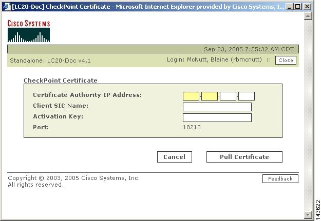
Add a Check Point Certificate Server
When defining a Check Point module that uses secured communications, you must identify the certificate sever that authenticates the SICs provided by the client and the server. Typically, a SmartCenter server or the CMA has its own certificate server, however, your configuration may use a central server. If that is the case, you must define the certificate server as part of a defining a base or child enforcement module.
Note
To define a certificate server, follow these steps:
Step 1
Step 2
•
•
•
Step 3
Result: A message box appears stating "Discovery is done."
A certificate can be pulled only once for an OPSEC Application. If for any reason the pull operation fails, you must reset the certificate using the CheckPoint SmartDashboard. For more information, see Reset the OPSEC Application Certificate of the MARS Appliance.
Step 4
Edit Discovered Log Servers on a Check Point Primary Management Station
After performing a discovery operation, you must edit each discovered log servers. The purpose of editing this log server is to identify that it is its own log server and to provide the SIC communication settings.
To edit a discovered log server, follow these steps:
Step 1
Step 2
Step 3
•
•
•
Step 4
•
•
•
Step 5
Step 6
Edit Discovered Firewall on a Check Point Primary Management Station
After performing a discovery operation, you must edit any discovered firewalls. You must specify which log server the firewall uses, define the route information, and if you want to monitor resource utilization, you must specify the SNMP RO community string.
Note
Note
To edit a discovered firewall, follow these steps:
Step 1
Step 2
Step 3
Before you can specify the SNMP RO string, you must define an access IP address on host that represents the primary management station. MARS uses the SNMP RO string to read MIBs related to a reporting device's CPU usage, network usage, and device anomaly data and to discover device and network settings.
Step 4
Step 5
Step 6
Step 7
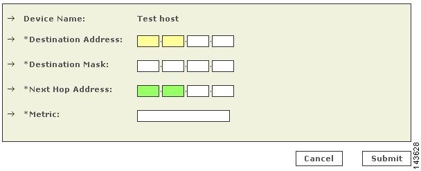
Define Route Information for Check Point Firewall Modules
To perform attack path analysis and to provide suggested mitigation configurations, MARS must understand the static routes that are defined on a firewall module. This requirement is true for firewalls running on the primary management station as well as for each firewall child enforcement module managed by the primary management station. To provide this information, you must define the routes manually in the MARS web interface. You will need a list of the routes for all interfaces in the firewall before you attempt to enter this information.
Note
To define the static routes used by a firewall, follow these steps:
Step 1
•
•
Result: The Route Information dialog box appears.
Step 2
•
•
•
•
A metric is a measurement of the cost of a route based on the number of hops (hop count) to the network on which a specific host resides. Hop count refers to the number of networks that a network packet must traverse, including the destination network, before it reaches its final destination. Because the hop count includes the destination network, all directly connected networks have a metric of 1. For the metric value, specify a number between 1 and 15.
Step 3
Step 4
Step 5
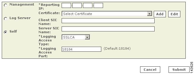
Specify Log Info Settings for a Child Enforcement Module or Log Server
There are two occasions when you must define the log settings manually:
•
•
Three options exist for manually specifying the log settings:
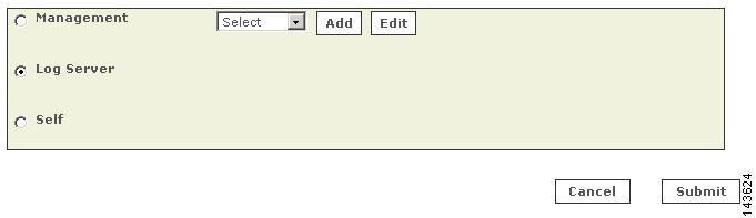
•
Figure 4-1 Log Information Published to Primary Management Station
•
•
To specify the log server settings of a child enforcement module manually, follow these steps:
Step 1
•
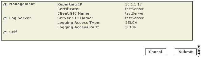
Figure 4-2 Log Information Published to Self
•
Result: The Log Information dialog box appears, and the desired option is selected.
Step 2
•
•
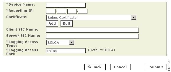
Step 3
•
•
•
•
Step 4
•
•
•
Step 5
Step 6
Result: The submit operation records the changes in the database tables. However, it does not load the changes into working memory of the MARS Appliance. The activate operation loads submitted changes into working memory.
Step 7
Step 8
Result: Once the MARS Appliance is activated, it connects to the Check Point log modules and retrieves the traffic and audit logs. MARS also begins to sessionize events generated by this device and its modules and evaluate those events using the defined inspection and drop rules. Any events published by the device to MARS before activation can be queried using the reporting IP address of the device as a match criterion. For more information on the activate action, see Activate the Reporting and Mitigation Devices, page 2-27.
Verify Connectivity Between MARS and Check Point Devices
After defining the Check Point device and clicking Activate in the MARS web interface, the MARS Appliance connects to the log servers and pulls the traffic and audit logs stored on them. You can verify that these transactions are successful using the following method:
•
Result: The netstat command should display two connections per log server.
Remove a Firewall or Log Server from a Check Point Primary Management Station
If the configuration of your network changes so that a firewall or log server is no longer managed by the primary management station under which it is defined, you must remove the child enforcement module.
To remove a child enforcement module from the primary management station, follow these steps:
Step 1
Step 2
Such devices have CheckPoint Management Console as an entry in the Device Type column.
Step 3
Step 4
The Access Information page appears.
Step 5
Step 6
Result: The Confirmation screen appears.
Step 7
Troubleshooting MARS and Check Point
The following information can be used to troubleshoot communicate issues between the MARS Appliance and Check Point components.
•
•
Note
•
Common reasons for failure of device discovery are as follows:
•
•
•
•
•
•
•
•
•
For additional Check Point discovery-related debug information, use the pnlog command at the CLI of the MARS Appliance. You can use the cpdebug attribute to specify appropriate debug level. Level 9 presents all debug messages. You can view the debug messages using the pnlog showlog cpdebug command at the CLI. For more information on pnlog, see pnlog, page A-30 in the Install and Setup Guide for Cisco Security Monitoring, Analysis, and Response System.