Feedback
Table Of Contents
Hardware and Software Requirements
Installation and Removal Instructions
Verifying the Status of AIP-SSM
Installing AIP-SSM
This chapter describes how to install AIP-SSM. It contains the following sections:
•
Hardware and Software Requirements
•
Specifications
Table 6-1 lists the specifications for AIP-SSM:
Table 6-1 IDSM-2 Specifications
Dimensions (H x W x D)
1.70 x 6.80 x 11.00 inches
Weight
Minimum: 2.50 lb
Maximum: 3.00 lb1Operating temperature
+32° to +104°F (+0° to +40°C)
Nonoperating temperature
-40° to +167°F (-40° to +75°C)
Humidity
10% to 90%, noncondensing
1 2.70 lbs for 45 c heatsink, approximately 3.00 lbs for the 55c maximum
Memory Specifications
Table 6-2 lists the memory specifications for AIP-SSM.
Table 6-2 AIP-SSM Memory Specifications
AIP-SSM-10
2.0 GHz Celeron
1.0 GB
AIP-SSM-20
2.4 GHz Pentium 4
2.0 GB
Hardware and Software Requirements
AIP-SSM has the following hardware and software requirements:
•
–
–
–
•
•
•
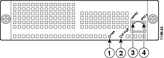
Indicators
Figure 6-1 shows the AIP-SSM indicators.
Figure 6-1 AIP-SSM Indicators
Table 6-3 describes the AIP-SSM indicators.
Installation and Removal Instructions
This section describes how to install and remove AIP-SSM, and contains the following topics:
•
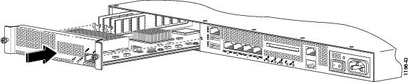
Installing AIP-SSM
To install AIP-SSM, follow these steps:
Step 1
Step 2
For more information, see Working in an ESD Environment.
Step 3
Step 4
Step 5
Step 6
Step 7
If AIP-SSM is properly installed, the POWER indicator is solid green and the STATUS indicator is flashing green. You can also verify that AIP-SSM is online using the show module command. For more information, see Verifying the Status of AIP-SSM.
Step 8
For the procedure, see Initializing the Sensor.
Step 9
See Obtaining Cisco IPS Software for the procedure.
Step 10
For the procedure, refer to Sending Traffic to AIP-SSM.
For More Information
•
•
–
–
Verifying the Status of AIP-SSM
You can use the show module 1 command to verify that AIP-SSM is up and running.
To verify the status of AIP-SSM, follow these steps:
Step 1
Step 2
asa# show module 1Mod Card Type Model Serial No.--- -------------------------------------------- ------------------ -----------1 ASA 5500 Series Security Services Module-20 ASA-SSM-20 P2B000005D0Mod MAC Address Range Hw Version Fw Version Sw Version--- --------------------------------- ------------ ------------ ---------------1 000b.fcf8.0144 to 000b.fcf8.0144 0.2 1.0(9)0 5.0(0.27)S129.0Mod Status--- ------------------1 Upasa#If the status reads
Up, AIP-SSM has been properly installed.The following values are valid for the Status field:
•
•
•
•
•
•
•
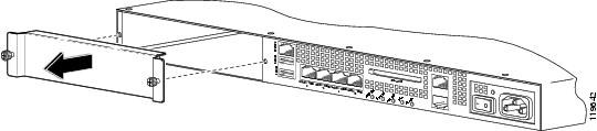
Removing AIP-SSM
To remove AIP-SSM, follow these steps:
Step 1
asa# hw-module module 1 shutdownShutdown module in slot 1? [confirm]Step 2
Step 3
Step 4
Step 5
For more information, see Working in an ESD Environment.
Step 6
Step 7
Step 8
Note
Step 9
Step 10
Step 11
asa# hw-module module 1 resetReset module in slot 1? [confirm]Step 12
Step 13
If AIP-SSM is properly installed, the POWER indicator is solid green and the STATUS indicator is flashing green. Or you can verify installation using the show module command. For the procedure, see Verifying the Status of AIP-SSM.