Table Of Contents
Cisco CRS-1 16-Slot Multishelf System Overview
Fabric Card Chassis Components
Line Card Chassis Components
Multishelf System Control Network (Cisco Catalyst 6509 Switch)
Multishelf System Control Network (22-Port SCGE Cards)
Cisco CRS-1 16-Slot Multishelf System Overview
This chapter describes the Cisco CRS-1 16-Slot Carrier Routing System Multishelf System. Various configurations of the 16-slot multishelf system (MSS) exist. This publication describes 16-slot MSS and 16-slot fabric card chassis (FCC) site planning considerations. A 16-slot MSS is made up of
Cisco CRS-1 16-slot FCCs and Cisco CRS-1 16-slot LCCs. Older configurations also include Cat6509 switches.
The multishelf system is made up of two LCCs and up to four FCCs. Older MSS configurations include one or two Cat6509 switches, which provide the control network for the MSS. Note that two Cat6509 switches are required for redundancy. Current releases of the FCC include one or two 22-port shelf controller Gigabit Ethernet (22-Port SCGE) cards, which provide the control network for the multishelf system. Note that two 22-Port SCGE cards are required for redundancy.
Note
If your FCCs are equipped with 22-Port SCGE cards, your MSS does not require Cat6509 switches.
Figure 1-1 shows the single-FCC multishelf system. Figure 1-2 shows the two-FCC multishelf system, and Figure 1-3 shows the four-FCC multishelf system. The following sections describe each of the major components:
•
Fabric Card Chassis Components
•
Line Card Chassis Components
•
Multishelf System Control Network (Cisco Catalyst 6509 Switch)
•
Multishelf System Control Network (22-Port SCGE Cards)
Figure 1-1 Single-FCC Multishelf System
1
|
Cisco CRS-1 16-Slot Line Card Chassis (two required)
|
3
|
Cisco Catalyst 6509 Switch (two suggested)1
|
2
|
Cisco CRS-1 Fabric Card Chassis (one required)
|
|
|
Figure 1-2 Two-FCC Multishelf System
1
|
Cisco CRS-1 16-Slot Line Card Chassis (two required)
|
3
|
Cisco Catalyst 6509 Switch (two suggested)1
|
2
|
Cisco CRS-1 Fabric Card Chassis (two required)
|
|
|
Figure 1-3 Four-FCC Multishelf System
1
|
Cisco CRS-1 16-Slot Line Card Chassis (two required)
|
3
|
Cisco Catalyst 6509 Switch (two suggested)1
|
2
|
Cisco CRS-1 Fabric Card Chassis (four required)
|
|
|
Fabric Card Chassis Components
This section lists the main components of the fabric card chassis. It primarily identifies the components that are considered field-replaceable units (FRUs) and, for which additional detail is useful, identifies components that are not field replaceable.
The fabric card chassis contains:
•
Eight S2 switch fabric cards. These cards provide Stage 2 of the three-stage Benes switch fabric for the multishelf system. S13 switch fabric cards in the line card chassis provide Stage 1 and Stage 3 of the switch fabric. When multiple FCCs are installed in a multishelf system, the S2 switch fabric cards are distributed across the FCCs.
The switch fabric receives user data from one MSC and PLIM pair and performs the switching necessary to route the data to the appropriate egress MSC and PLIM pair.
•
Optical interface modules (OIMs) and cables. Each S2 fabric card plugs into one side of an OIM, and the multishelf system fabric cables plug into the other side of the OIM. The fabric cables are optical array cables that are installed between the FCCs and LCCs to connect the S2 and S13 fabric cards to each other.
•
Two 2-port shelf controller Gigabit Ethernet (SCGE) cards. These cards control the S2 switch fabric cards. They also control the chassis fans, varying their speed to adjust the airflow for ambient conditions. Only one shelf controller card is active at a time. The second acts as a "standby" shelf controller, serving as a backup if the active card fails.
or
•
Two 22-port shelf controller Gigabit Ethernet (SCGE) cards. These cards control the S2 switch fabric cards. They also control the chassis fans, varying their speed to adjust the airflow for ambient conditions. Only one shelf controller card is active at a time. The second acts as a "standby" shelf controller, serving as a backup if the active card fails. The 22-port SCGE card also includes integrated switching functionality. This eliminates the need for the 2-port SCGE cards and external Cisco Catalyst switches.
•
A power system that provides 8800 watts (8.8 kW) of redundant DC output power for the chassis. The AC power system consists of two AC power shelves with three AC rectifier modules in each power shelf. The DC power system consists of two DC power shelves with two DC power entry modules (PEMs) in each power shelf. Each power shelf supplies input power to the rectifiers or PEMs, which in turn provide processed power to the chassis.
•
Two alarm modules. The alarm modules provide external alarm system connections. The alarm modules are located in the AC or DC power shelves.
•
A chassis backplane. The backplane distributes power to the components in the chassis and connects the components to each other. The S2 switch fabric cards and shelf controller cards plug into the backplane. The backplane is not field replaceable by the customer.
•
Upper and lower fan trays. The fan trays contain fans that push and pull air through the chassis. A removable air filter is also located above the lower fan tray.
The switch fabric cards are located at the front of the FCC. The optical interface modules (OIMs) are located at the rear of the chassis. The fabric cables (that interconnect the switch fabric cards) plug into the OIMs.
Cool air enters at the front of the chassis and warm air is exhausted at the rear.
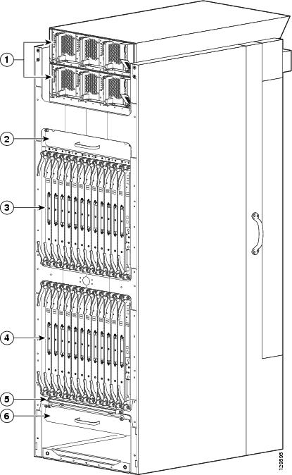
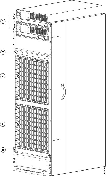
Figure 1-4 and Figure 1-5 show the front and rear views of the fabric card chassis.
Figure 1-4 Fabric Card Chassis (Front)
1
|
Power shelves (with alarm modules)
|
4
|
Lower card cage
|
2
|
Upper fan tray
|
5
|
Air filter
|
3
|
Upper card cage
|
6
|
Lower fan tray
|
Figure 1-5 Fabric Card Chassis (Rear)
1
|
Power shelves
|
4
|
Lower card cage
|
2
|
Upper fan tray (accessible from front)
|
5
|
Lower fan tray (accessible from front)
|
3
|
Upper card cage
|
|
|
Line Card Chassis Components
Note
The LCC can also be used as a stand-alone unit. However, FCCs are only used in conjunction with an MSS. A separate set of LCC documentation is available. See the Cisco CRS-1 Carrier Routing System Hardware Documentation Guide for more information. This guide details site planning guidelines for the MSS and the FCC only.
The Cisco CRS-1 LCC contains:
•
As many as 16 modular services cards (MSCs), also called line cards, and 16 physical layer interface modules (PLIMs) or SPA interface processors (SIPs). The MSC and PLIM or SIP are an associated pair of cards that mate through the chassis midplane. The MSC provides the forwarding engine for Layer 3 routing of user data, and the PLIM or SIP provides the physical interface and connectors for the user data.
PLIMs and SIPs are described in the following documents:
–
Cisco CRS-1 Carrier Routing System Packet-over-SONET/SDH Physical Layer Interface Module (PLIM) Installation Note
–
Cisco CRS-1 Carrier Routing System Gigabit Ethernet Physical Layer Interface Module (PLIM) Installation Note
–
Cisco CRS-1 SIP and SPA Hardware Installation Guide
•
A chassis midplane. The midplane connects MSCs to their associated PLIMs and allows an MSC to be removed from the chassis without having to disconnect the cables that are attached to the associated PLIM. The midplane distributes power, connects the MSCs to the switch fabric cards, and provides control plane interconnections. The midplane is not field replaceable by the customer.
•
Two route processor cards (RPs). The RPs provide the intelligence of the system by functioning as the LCC system controller and performing route processing. Only one RP is active at a time. The second RP acts as a "standby" RP, serving as a backup if the active RP fails.
The RP also monitors system alarms and controls the system fans. LEDs on the front panel indicate active alarm conditions.
•
(Optional) One or more distributed route processor cards (DRPs), each with a corresponding PLIM. Each DRP and DRP PLIM function as an additional route processor (RP) in the system, providing additional route processing for the Cisco CRS-1 router. By offloading processor-intensive tasks (such as BGP speakers and ISIS) from the RP to the DRP, you can improve system performance.
•
Eight switch fabric cards. These fabric cards provide switch fabric components for the system. The switch fabric receives user data from one MSC and PLIM pair and performs the switching necessary to route the data to the appropriate egress MSC and PLIM pair.
–
As a standalone system (single shelf), the LCC contains S123 fabric cards that provide all three stages of the three-stage Benes switch fabric.
–
As part of a multishelf system, the LCC contains S13 fabric cards that provide Stage 1 and Stage 3 of the switch fabric. S2 fabric cards in the FCCs provide Stage 2 of the fabric, and fabric cables connect the fabric cards to each other.
•
Two fan controller cards. These cards control the chassis fans, varying their speed to adjust the airflow for ambient conditions.
•
Two AC or two DC power shelves with three AC rectifiers or DC power entry modules (PEMs) in each power shelf. The power shelves and AC rectifiers or DC PEMs provide 13.2 kilowatts of redundant power for the system.
•
Two alarm modules. The alarm modules provide external alarm system connections. The alarm modules are located in the AC or DC power shelves.
•
Upper and lower fan trays. The fan trays contain fans that push and pull air through the chassis. A removable air filter is located above the lower fan tray.
Multishelf System Control Network (Cisco Catalyst 6509 Switch)
One or two Cat6509s provide a control network for the control traffic of the multishelf system. The Cat6509 switch is cabled to both the LCCs and FCCs. Although the multishelf system can operate with a single Cat6509, we recommend that you install two Cat6509 switches for redundancy.
Note
If you operate the multishelf system with only a single Cat6509 switch, any failure of the Cat6509 leaves the multishelf system with no control network.
See the "Control Network (Cisco Catalyst 6509 Switch)" section for information about the Cat6509 switch requirements. See the Cisco CRS-1 Carrier Routing System Multishelf System Interconnection and Cabling Guide for information about how to cable the Cat6509 to the LCCs and FCCs.
Multishelf System Control Network (22-Port SCGE Cards)
One or two 22-Port SCGE cards provide a control network for the multishelf system. The 22-Port SCGE cards are cabled from the RPs in the LCCs to the 22-port SCGE cards in the FCC(s). Although the multishelf system can operate with a single 22-Port SCGE card, we recommend that you install two 22-Port SCGE cards for redundancy.
Note
We recommend operating the system with two 22-port SCGE cards for redundancy. If you operate the multishelf system with only a single 22-Port SCGE card, any failure of the 22-Port SCGE card leaves the multishelf system with no control network.
See the "Control Network (22-Port SCGE Card)" section for information about the 22-Port SCGE card requirements. See the Cisco CRS-1 Carrier Routing System Multishelf System Interconnection and Cabling Guide for information about how to cable the 22-Port SCGE card to the LCCs.
Note
Cisco Catalyst switches and the 2-port SCGE cards are eliminated from the MSS if the fabric card chassis is equipped with 22-port SCGE cards.