Table Of Contents
Location and Mounting Requirements
Distance Limitations for Interface Cables
T1-PBX Digital Voice Port Maximum Distances
FXS Analog Voice Port Maximum Distance
FXO Analog Voice Port Maximum Distance
Planning Your Installation
Before you install your Cisco IAD2420 series IAD, consider the information in this chapter:
•
Location and Mounting Requirements
•
Location and Mounting Requirements
The three mounting possibilities for your Cisco IAD are:
•
•
•
The mounting location must provide:
•
•
•
To ensure that these requirements are met, read this chapter before you begin the installation.
Heat Dissipation
The room where the Cisco IAD is operated must maintain a temperature of 32 to 122°F (0 to 50°C) and must have adequate air circulation to ensure proper cooling.
Enclosed racks must have adequate ventilation. An enclosed rack should not be overcrowded and should have louvers and a fan.
Make sure that the ventilation ports of the Cisco IAD are not blocked. If the chassis is installed using slide rails, check for blocked ventilation ports when it is fully in position.
If the Cisco IAD is installed in an enclosed rack with a ventilation fan at the top, make sure that heated air drawn upward is not too hot for adequate cooling.
Baffles can help isolate exhaust air from intake air, which also helps draw cooling air through the chassis. The best placement of the baffles depends on the airflow patterns in the rack, which are found by experimenting with different arrangements.
Caution
Access to Chassis
Allow space at the rear of the chassis for cable connections. Also consider the need to access the chassis for future upgrades, maintenance, and troubleshooting.
Power Source
If you suspect that your AC power is not clean—if lights flicker often or there is machinery with large motors nearby—have a qualified person test the power. Install a power conditioner if necessary.
Warning
Warning
Warning
Warning
Warning
Caution
A Cisco IAD with AC power supply autoselects either 100-127 volt or 200-240 volt operation. AC versions include a 6-foot (1.8-meter) electrical power cord. (A label near the power cord indicates the correct voltage, frequency, current draw, and power dissipation.)
Synchronous Serial Interface
Before you connect a device to the synchronous serial port (labeled SERIAL 0), you need to know the following:
•
•
•
DTE or DCE
A device that communicates over a synchronous serial interface is either a DTE or DCE device. A DCE device provides a clock signal; a DTE device does not provide a clock signal. DTE devices usually connect to DCE devices. The documentation that shipped with the device should indicate whether it is a DTE or DCE device. (Some devices have a jumper to select either mode.) If you cannot find the information in the documentation, refer to Table 2-1 to help you select the proper device type. The synchronous serial ports on a Cisco IAD can be configured as DTE or DCE (opposite to the device being connected).
Table 2-1 Typical DTE and DCE Devices
DTE
Male1
•
•
•
DCE
Female2
•
•
•
1 If pins protrude from the face of the connector, the connector is male.
2 If the connector face has holes to accept pins, the connector is female.
3 CSU/DSU = channel service unit/data service unit.
Signaling Standards
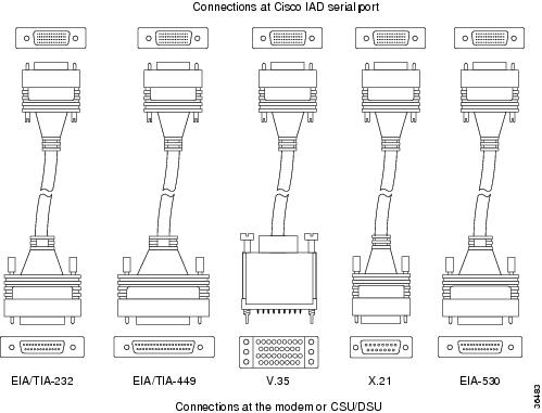
The synchronous serial port supports the following signaling standards: EIA/TIA-232, EIA/TIA-449, V.35, X.21, and EIA/TIA-530. You can order a shielded serial transition cable for your application. One end of this cable has a DB-60 connector, which connects to one of the serial ports on your Cisco IAD. The other end has the connector required for the signaling standard being used. The documentation for the device you want to connect to should indicate the standard used for that device.
Note
Figure 2-1 shows the serial transition cables you can connect to the serial port on the rear panel of the Cisco IAD.
Figure 2-1 Serial Transition Cables
Although attempting to manufacture your own serial cables is not recommended (because of the small size of the pins on the DB-60 serial connector), cable pinouts are provided in "Cable Specifications." To order a cable, see the "Obtaining Technical Assistance" section.
Timesaver
EIA/TIA-232 Connections
The EIA/TIA-232 standard supports unbalanced circuits at signal speeds up to 64 kbps.
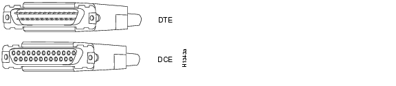
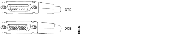
The EIA/TIA-232 serial transition cable (not included) has a DB-60 connector for connection to a Cisco IAD serial port. The opposite end has a DB-25 connector, as shown in Figure 2-2. The DB-25 connector can be male for DTE or female for DCE. To order a cable, see the "Obtaining Technical Assistance" section.
Figure 2-2 EIA/TIA-232 Serial Transition Cable Connectors
EIA/TIA-449 Connections
The EIA/TIA-449 standard, which supports balanced and unbalanced transmissions, is a faster (up to 2 Mbps) version of the EIA/TIA-232 standard that provides more functions and supports transmission over greater distances.
The EIA/TIA-449 standard was intended to replace the EIA/TIA-232 standard, but it was not widely adopted primarily because of the large installed base of DB-25 hardware, and because of the larger size of the 37-pin EIA/TIA-449 connectors, which limited the number of connections possible (fewer than are possible with the smaller, 25-pin EIA/TIA-232 connector).
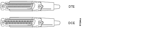
The EIA/TIA-449 serial transition cable (not included) has a DB-60 connector for connection to a Cisco IAD serial port. The opposite end has a DB-37 connector, as shown in Figure 2-3. The DB-37 connector can be male for DTE or female for DCE. To order a cable, see the "Obtaining Technical Assistance" section.
Figure 2-3 EIA/TIA-449 Serial Transition Cable Connectors
V.35 Connections
The V.35 standard is recommended for speeds up to 48 kbps, although in practice it is used successfully at 4 Mbps. The Cisco IAD supports speeds up to 2.048 Mbps.
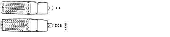
The V.35 serial transition cable (not included) has a DB-60 connector for connection to a Cisco IAD serial port. The opposite end has a standard 34-pin Winchester-type connector, as shown in Figure 2-4. The 34-pin Winchester-type connector can be male for DTE or female for DCE. To order a cable, see the "Obtaining Technical Assistance" section.
Figure 2-4 V.35 Serial Transition Cable Connectors
X.21 Connections
The X.21 connector uses a 15-pin connector for balanced circuits and is commonly used in the United Kingdom to connect to the public data network. X.21 relocates some of the logic functions to the DTE and DCE interfaces and, as a result, requires fewer circuits and a smaller connector than EIA/TIA-232.
The X.21 serial transition cable (not included) has a DB-60 connector for connection to a Cisco IAD serial port. The opposite end has a DB-15 connector, as shown in Figure 2-5. The DB-15 connector can be male for DTE or female for DCE. To order a cable, see the "Obtaining Technical Assistance" section.
Figure 2-5 X.21 Serial Transition Cable Connectors
EIA/TIA-530 Connections
The EIA/TIA-530 standard, which supports balanced transmission, provides the increased functionality, speed, and distance of EIA/TIA-449 on the smaller, DB-25 connector used for EIA/TIA-232. Like EIA/TIA-449, EIA/TIA-530 refers to the electrical specifications of EIA/TIA-422 and EIA/TIA-423. Although the specification recommends a maximum speed of 2 Mbps, EIA/TIA-530 is used successfully at 4 Mbps or faster speeds over short distances. Cisco IADs support speeds up to 2.048 Mbps.
The EIA/TIA-530 serial transition cable (not included) has a DB-60 connector for connection to a Cisco IAD serial port. The opposite end has a DB-25 connector, as shown in Figure 2-6. The DB-25 connector can be male for DTE or female for DCE. To order a cable, see the "Obtaining Technical Assistance" section.
Figure 2-6 EIA/TIA-530 Serial Transition Cable Connectors
Distance Limitations for Interface Cables
When planning your installation, consider distance limitations and potential electromagnetic interference (EMI) as defined by the Electronic Industries Association (EIA). Distance limitation information is included for the following IAD ports:
•
•
•
•
•
Ethernet Maximum Distance
The maximum segment distance for Ethernet 10BASE-T is 330 feet (100 meters) (specified in IEEE 802.3).
T1-WAN Port Maximum Distances
The distance limitations for T1 signals are shown in Table 2-2 (specified in ANSI T1.403).
Table 2-2 T1- WAN Port Distance Limitations
T1 (CSU)
6200
1890
DSL Port Maximum Distances
The distance limitations for DSL signals are shown in Table 2-3.
Table 2-3 DSL Port Distance Limitations
ADSL
15,000
4570
G.992.1 for G.dmt
G.992.2 for splitterlessSHDSL
23,000
7010
G.991.2
Serial Port Maximum Distances
Table 2-4 shows the standard relationship between baud rate and maximum distance for EIA/TIA-232 signals.
Table 2-4 EIA/TIA-232 Speed and Distance Limitations
2400
200
60
4800
100
30
9600
50
15
19200
25
8
38400
12
4
Caution
Table 2-5 shows the standard relationship between baud rate and maximum distance for EIA/TIA-449, V.35, and X.21 signals.
Caution
Table 2-6 shows the standard relationship between baud rate and maximum distance for EIA/TIA-530 signals.
Table 2-6 EIA/TIA-530 Speed and Distance Limitations
Up to 90000
3940
1200
110000
460
140
120000
425
130
130000
395
120
1000000
330
100
T1
230
70
E1
197
60
T1-PBX Digital Voice Port Maximum Distances
The maximum distances between the digital voice port of a Cisco IAD and a digital PBX are shown in Table 2-7.
Table 2-7 Digital Voice Port Speed and Distance Limitations
T1 (CSU)
3000
915
FXS Analog Voice Port Maximum Distance
The maximum distance is established by a total allowable loop resistance, including the phone or terminal equipment, of 600 ohms.
FXO Analog Voice Port Maximum Distance
The maximum distance is determined by the PBX or other equipment that provides battery and connects to the FXO voice port.
Interference Considerations
When you run cables for any significant distance in an electromagnetic field, interference can occur between the electromagnetic field and the signals on the cables. This has two implications for the installation of terminal plant cabling:
•
•
If you use twisted-pair cables with a good distribution of grounding conductors in your plant cabling, emitted radio interference is unlikely.
If you have cables exceeding recommended distances, or if you have cables that pass between buildings, give special consideration to the effect of lightning strikes or ground loops. If your site has these characteristics, consult experts in lightning suppression and shielding. The electromagnetic pulse caused by lightning or other high-energy phenomena can easily couple enough energy into unshielded conductors to destroy electronic devices.
Most data centers cannot resolve the infrequent, but potentially catastrophic problems just described without pulse meters and other special equipment. Take precautions to avoid these problems by providing a properly grounded and shielded environment and by installing electrical surge suppression.
If you remove any module, you must either install a module in its place or install a cover plate over the opening. All module openings must be either occupied or covered to prevent electromagnetic interference.
For advice on the prevention of electromagnetic interference, consult experts in radio-frequency interference (RFI).