Feedback
Table Of Contents
Powering On the Cisco AS5800 and Observing Initial Startup Conditions
Observing Power-Entry Module LEDs
Observing Dial Shelf Controller Card LEDs
Observing Router Shelf Port Adapter LEDs
Viewing Your System Configuration
Powering On the Cisco AS5800 and Observing Initial Startup Conditions
This chapter explains how to power on the Cisco AS5800 and confirm normal system startup LED readings, and then confirm that the proper software is running on the router shelf and dial shelf.
Powering On the Cisco AS5800
After you have installed your dial shelf and router shelf and connected the cables, you are ready to start up the system by powering on the following components:
•
Dial shelf
•
•
Before you power on the Cisco AS5800, you might want to prepare a terminal connection to view the software startup sequence. See the "Connecting to the Router Shelf Console and Auxiliary Ports" section for details on setting up a terminal connection. You should also confirm the LED indications as shown in the "Observing Access Server LEDs" section.
To power on the system, follow these steps:
Step 1
Step 2
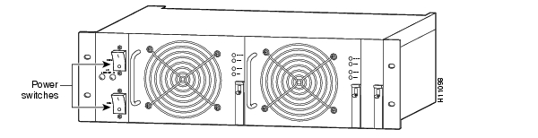
Figure 4-1 AC-Input Power Shelf—Front View
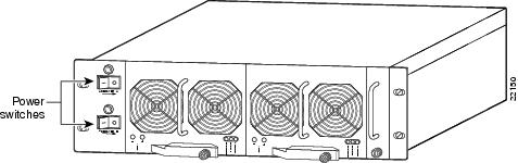
Figure 4-2 Enhanced AC-Input Power Shelf—Front View
Step 3
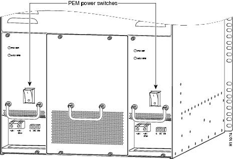
Figure 4-3 PEM Power Switches
Step 4
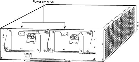
Figure 4-4 Router Shelf Power Switches—Rear View
Step 5
During the boot process, the LEDs on most of the port adapters in the router shelf and on the dial shelf cards and dial shelf controller cards light on and off in irregular sequence while the system is running initial self-diagnostic tests. On the router shelf I/O controller, the I/O power OK LED comes on immediately.
For a description of normal dial shelf LED states, proceed to the "Observing Access Server LEDs" section. Normal router shelf startup is discussed in the "Starting the Cisco 7206" section. If everything seems to be normal, complete the startup check with a console connection as described in the "Viewing Your System Configuration" section.
Observing Access Server LEDs
This section describes the normal LED states for the following components:
•
•
•
•
Nominal LED Readings
provides a quick reference for nominal LED readings for Cisco AS5800 components. If LED readings vary from those listed, refer to the relevant sections for more details.
Dial Shelf Card LEDs
LEDs for the individual CT1/CE1 trunk cards, DMM modem cards, and Voice over IP (VoIP) cards are described in the Cisco AS5800 Universal Access Server Dial Shelf Card Guide. Nominal LED readings are briefly listed in .
Observing Power-Entry Module LEDs
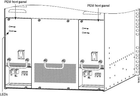
The PEMs contain two LEDs on the front panel—POWER and MISWIRE. (See .)
•
•
If either of these LEDs functions abnormally, proceed to "."
shows the location of the PEM LEDs.
Figure 4-5 PEM Front Panel LEDs
Observing Dial Shelf Controller Card LEDs
The dial shelf controller card front panel contains several LEDs. Unlike the other dial shelf cards installed in the Cisco 5814 dial shelf, the dial shelf controller card has two power LEDs, one for the dial shelf controller card power and the other for the system MBus power.
shows the dial shelf controller card front panel LEDs, and describes the LED functions.
If the dial shelf controller card LEDs function abnormally, proceed to "."
Figure 4-6 Dial Shelf Controller Card Front Panel LEDs
Table 4-3 Dial Shelf Controller Card Front Panel LEDs
PWR (dial shelf controller power)
Green
Lights when power is ON.
MBUS (system MBus power)
Green
Lights when the dial shelf controller card is supplying +5 VDC to the system MBus.
MAJ (major alarm)
Yellow
Lights to indicate a major1 alarm condition.
MIN (minor alarm)
Yellow
Lights to indicate a minor2 alarm condition.
ACO (alarm cutoff)
Yellow
Lights when the alarm cutoff button has been pressed during a major or minor alarm. Turns off when the original alarm clears or any new alarm occurs.
HIST (history clear)
Yellow
Lights when software recognizes a major or minor alarm situation. LED powers off when the Clear Alarm button is pressed and no alarm condition remains.
CLK (clock)
Green
Lights to identify the dial shelf controller card active clock; active clock is independent from master dial shelf controller card designation.
MAST (master)
Green
Lights to indicate the system software recognizes the dial shelf controller card is in master mode.
Slot 0
Green
Lights when PCMCIA slot 0 is in use.
Slot 1
Green
Lights when PCMCIA slot 1 is in use.
DSI (dial shelf interconnect)
Green
Lights to indicate a working connection between the dial shelf and router shelf.
10BaseT (Ethernet link)
Green
Lights to indicate a working data transfer link connection between the access server and the system controller.
LCDs (upper and lower)
Alphanumeric; 4 characters each
Displays MSTR to indicate master card.
1 A major alarm condition includes router shelf failure, backplane interconnect failure, two-fan failure, power supply failure, dial shelf card failure, or conditional environmental thresholds.
2 A minor alarm condition includes modem SIMM failure, HDLC controller failure, trunk line failure, or conditional environmental thresholds.
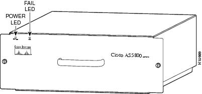
Blower Assembly LEDs
Two LEDs—Power and Fault—are mounted on the blower assembly front panel (see ) and function as described in .
Figure 4-7 Blower Assembly—Front View
If you detect a problem with the blower assembly LEDs, proceed to "."
Starting the Cisco 7206
After installing your Cisco 7206 and connecting the cables, start each router as follows:
Step 1
•
•
•
•
•
•
Step 2
Step 3
Step 4
Step 5
Cisco Internetwork Operating System SoftwareIOS (tm) 7200 Software (C5800-p4-mz), 12.0(19970915:09303]Copyright (c) 1986-1999 by cisco Systems, Inc.Compiled Mon 01-Dec-99 06:00 by ...
Note
Step 6
--- System Configuration Dialog ---At any point you may enter a questions mark '?' for help. Use ctrl-c to abort configuration dialog at any prompt. Default settings are in square brackets '[]'.Continue with configuration dialog? [yes]:You have the option of proceeding with the setup command facility to configure the interfaces, or exiting from setup and using configuration commands to configure global (system-wide) and interface-specific parameters. You do not have to configure the interfaces immediately; however, you cannot enable the interfaces or connect them to any networks until you have configured them.
Many of the port adapter LEDs will not go on until you have configured the interfaces. To verify correct operation of each interface, complete the first-time startup procedures and configuration, then refer to the configuration note for each port adapter for LED descriptions and to check the status of the interfaces.
Observing Router Shelf Port Adapter LEDs
The router shelf port adapters contain enabled LEDs, which must be on for the system to be operational. Refer to the Cisco 7206 Installation and Configuration Guide for a description of router shelf port adapter LEDs.
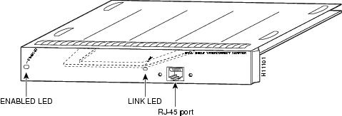
Unique to the Cisco AS5800 is the interconnect port adapter that installs in the router shelf. The dial shelf interconnect contains two LEDs: an enabled LED and a link status LED, shown in . After system initialization, the enabled LED lights to indicate that the dial shelf interconnect has been enabled for operation.
Figure 4-8 Dial Shelf Interconnect Port Adapter Front Panel
The following conditions must be met before the router shelf port adapters and the dial shelf interconnect are enabled:
•
•
•
If any of the above conditions are not met, or initialization fails for other reasons, the enabled LED will remain off. Refer to the chapter "," later in this publication, for router shelf LED troubleshooting tips.
Viewing Your System Configuration
When you start up your access server for the first time, the router shelf console displays the Cisco IOS software information that is loaded on your system if you have connected a terminal as described in the "Connecting to the Router Shelf Console and Auxiliary Ports" section. From this startup software banner (see the following example), you can identify the Cisco IOS software release version, other platform images that support system component functionality, and installed internal hardware components.
System Bootstrap, Version 12.0(4)XJ, RELEASED SOFTWARECopyright (c) 1994-1999 by Cisco Systems, Inc.AS5800 processor with 32768 Kbytes of main memoryRestricted Rights LegendUse, duplication, or disclosure by the Government issubject to restrictions as set forth in subparagraph(c) of the Commercial Computer Software - RestrictedRights clause at FAR sec. 52.227-19 and subparagraph(c) (1) (ii) of the Rights in Technical Data and ComputerSoftware clause at DFARS sec. 252.227-7013.Cisco Systems, Inc.170 West Tasman DriveSan Jose, California 95134-1706Cisco Internetwork Operating System SoftwareIOS (tm) 7200 Software (C5800-p4-mz), 12.0(19970915:09303]Copyright (c) 1986-1999 by Cisco Systems, Inc.Compiled Mon 01-Dec-99 06:00 byImagetext-base: 0x600088C0, data-base: 0x60940000ROM: System Bootstrap, Version 12.0(4)XJ [dschwart 10], RELEASE SOFTWARE (fc1)Cisco 7206 (NPE200) processor with 57344K/8192K bytes of memory.R4700 processor, Implementation 33, Revision 1.0 (512KB Level 2 Cache)Last reset from power-onChannelized E1, Version 1.0.X.25 software, Version 3.0.0.Primary Rate ISDN software, Version 1.0.4 Ethernet/IEEE 802.3 interface(s)1 FastEthernet/IEEE 802.3 interface(s)31 Serial network interface(s)72 terminal line(s)12 Channelized E1/PRI port(s)1 FE interface(s) for dial shelf to router shelf interconnect125K bytes of non-volatile configuration memory.1024K bytes of packet SRAM memory.16384K bytes of Flash PCMCIA card at slot 0 (Sector size 128K).4096K bytes of Flash internal SIMM (Sector size 256K).Configuration register is 0x0Your Cisco AS5800 should be running the following software:
•
•
•
•
If you find you have a different Cisco IOS software release on the router shelf or dial shelf, reload the correct software version. If you need to reload the software, refer to the Cisco AS5800 Software Installation and Configuration Guide that shipped with your Cisco AS5800. The Cisco AS5800 Universal Access Server Software Installation and Configuration Guide will be replaced by the Cisco AS5800 Universal Access Server Operation, Administration, Maintenance, and Provisioning Guide, available later this year.
If you established a terminal connection after initial startup, you can verify that the correct software is loaded by issuing the following commands at the terminal:
Step 1
User Access VerificationUsername: adminPassword:Step 2
5800> enablePassword:Step 3
5800# sh verCisco Internetwork Operating System SoftwareIOS (tm) 5800 Software (C5800-P4-M), Version 12.0(4)XJTAC:Home:SW:IOS:Specials for infoCopyright (c) 1986-1999 by Cisco Systems, Inc.Compiled Thu 12-Aug-99 13:16 by ayehImage text-base: 0x60008900, data-base: 0x611A6000ROM: System Bootstrap, Version 12.0(19990210:195103) [12.0XJ 105]BOOTFLASH: 7200 Software (C7200-BOOT-M), Version 12.0(4)XJnas-5800-01 uptime is 22 minutesSystem returned to ROM by power-onSystem image file is "slot0:c5800-p4-mz.120-4.XJ1.bin"Cisco 7206VXR (NPE300) processor with 253952K/40960K bytes of memory.R7000 CPU at 262Mhz, Implementation 39, Rev 1.0, 256KB L2, 2048KB L3 Cache6 slot VXR midplane, Version 2.0Last reset from power-onX.25 software, Version 3.0.0.Bridging software.SuperLAT software (copyright 1990 by Meridian Technology Corp).Primary Rate ISDN software, Version 1.1.8 Ethernet/IEEE 802.3 interface(s)1 FastEthernet/IEEE 802.3 interface(s)52 Serial network interface(s)288 terminal line(s)12 Channelized T1/PRI port(s)96 DSP(s), 192 Voice resource(s)125K bytes of non-volatile configuration memory.16384K bytes of Flash PCMCIA card at slot 0 (Sector size 128K).4096K bytes of Flash internal SIMM (Sector size 256K).Configuration register is 0x1025800#sh dial-shelfSlot Board CPU DRAM I/O Memory State ElapsedType Util Total (free) Total (free) Time0 CT1 0( 0%) 0( 0%) Resetting 00:03:202 Modem(DMM) 0%/0% 46764800( 86%) 16777216( 74%) Up 00:21:133 Modem(DMM) 0%/0% 46764800( 86%) 16777216( 74%) Up 00:21:134 Voice 0%/0% 46764800( 91%) 16777216( 71%) Up 00:21:1212 DSC 0%/0% 19097792( 79%) 8388608( 66%) Up 00:22:28Dial shelf set for auto bootStep 4
5800#execute-on slot 12 show verDA-Slot12>Cisco Internetwork Operating System SoftwareIOS (tm) 5800 Software (C5800-DSC-M), Version 12.0(4)XJTAC:Home:SW:IOS:Specials for infoCopyright (c) 1986-1999 by Cisco Systems, Inc.Compiled Thu 12-Aug-99 18:48 by ayehImage text-base: 0x600088F0, data-base: 0x60520000ROM: System Bootstrap, Version 12.0(4)XJ SOFTWARE (fc)ROM: 5800 Software (C5800-DSC-M), Version 12.0(4)XJDA-Slot12 uptime is 24 minutesSystem returned to ROM by power-onSystem image file is "slot0:dsc-c5800-mz.120-4.XJ1.bin"Cisco c5800 (R4K) processor with 24576K/8192K bytes of memory.R4700 CPU at 150Mhz, Implementation 33, Rev 1.0, 512KB L2 CacheLast reset from power-on1 Ethernet/IEEE 802.3 interface(s)2 Dial Shelf Interconnect(DSI) FE interface(s)123K bytes of non-volatile configuration memory.8192K bytes of Flash PCMCIA card at slot 0 (Sector size 128K).4096K bytes of Flash internal SIMM (Sector size 256K).Configuration register is 0x2102Refer to the Cisco AS5800 Universal Access Server Software Installation and Configuration Guide that shipped with your system for additional software configuration information. The Cisco AS5800 Universal Access Server Software Installation and Configuration Guide will be replaced by the Cisco AS5800 Universal Access Server Operation, Administration, Maintenance, and Provisioning Guide, available later this year.
Where to Go Next
Your access server is now installed, and all components are operative. When you power ON the access server for the first time, messages appear on your console screen. When the initialization process is complete, the console screen displays a script and system banner. At this point, you can begin to configure the software. The software configuration information is contained in the Cisco AS5800 Universal Access Server Software Installation and Configuration Guide. Proceed to this publication for information on how to run the initial setup script and create a basic configuration.The Cisco AS5800 Universal Access Server Software Installation and Configuration Guide will be replaced by the Cisco AS5800 Universal Access Server Operation, Administration, Maintenance, and Provisioning Guide, available later this year. The Cisco AS5800 Universal Access Server Operations, Administration, Maintenance, and Provisioning Guide provides information needed for ongoing hardware and software maintenance and operation tasks.
The remainder of this document includes reference material for troubleshooting your system and Cisco AS5800 specifications.